Cognex DataMan 150 Series Reference Manual
Id reader
Hide thumbs
Also See for DataMan 150 Series:
- Reference manual (173 pages) ,
- Quick reference manual (22 pages) ,
- Reference manual (150 pages)
Table of Contents
Advertisement
Advertisement
Table of Contents

Related Manuals for Cognex DataMan 150 Series


Summary of Contents for Cognex DataMan 150 Series
- Page 1 ® DataMan 150 Series Reference Manual 2021 May 26 Revision: 6.1.10-SR1.4...
-
Page 2: Legal Notices
Copyright © 2021. Cognex Corporation. All Rights Reserved. Portions of the hardware and software provided by Cognex may be covered by one or more U.S. and foreign patents, as well as pending U.S. and foreign patents listed on the Cognex web site at: cognex.com/patents. -
Page 3: Table Of Contents
Reader Layout Indicator LEDs Changing Orientation Dimensions Dimensional Drawings DataMan 150 Specifications DataMan 150 Series Imager Specifications LED Wavelengths Illumination Options Setting Up Your DataMan 150 Installing an Optical Filter Installing a Liquid Lens Changing a 6.2 mm Lens to a 16 mm Lens... - Page 4 Table of Contents RS-232 Connections Wiring the Basic I/O Module Digital Input Wiring Diagrams Digital Output Wiring Diagrams Multi-port Connections Using Your DataMan 150 Installing the DataMan Software Setting the Focus Position Tuning External Triggering and Trigger Modes Training and Trigger Modes Training Incremental Training for Multiple Symbologies Cleaning and Maintenance...
-
Page 5: Symbols
Symbols Symbols The following symbols indicate safety precautions and supplemental information: WARNING: This symbol indicates a hazard that could cause death, serious personal injury or electrical shock. CAUTION: This symbol indicates a hazard that could result in property damage. Note: This symbol indicates additional information about a subject. Tip: This symbol indicates suggestions and shortcuts that might not otherwise be apparent. -
Page 6: Getting Started
Getting Started Getting Started This section provides general information about the DataMan 150 series readers as well as about the DataMan 150 accessories and systems. About DataMan 150 The DataMan 150 readers are best in class ID readers, offering superior performance with the latest ID tools, flexibility to... -
Page 7: Dataman 150 Accessories
Cognex->DataMan Software v x.x.x->Documentation->English->Reader Configuration Codes The DM150 Quick Reference Guide provides essential information about the DM150 readers. Cognex->DataMan Software v x.x.x->Documentation->English->DM150 Series->DM150 Quick Reference Guide The DataMan Fixed-Mount Readers Reference is a complete online hardware reference for the DataMan fixed- mount ID readers. -
Page 8: Filters
Getting Started IR 6.2 mm lens kit, 3-position with IR LED (DMA-KIT-IR-62) 6.2 mm optics mount 6.2 mm lens (IR) Standard Infrared Light for 6.2mm (Risk Group Exempt acc. IEC62471) manual lens cap (not assembled) screws UV Light Kit for 6.2 mm lens (DMA-KIT-UV365-62) UV light board (365nm wavelength) UV resistant front cover screws... -
Page 9: Lens Covers
Getting Started Lens Covers Accessory Name and Number Accessory Image Clear lens cover (DM150-CVR-CLR)* Clear lens cover, ESD safe (DM150-CVR-ESD)* Polarized front cover (DM260-LENS-62CVR-F)* Extended lens cover, un-polarized (DM260-LENS-16CVR)** Extended lens cover, half-polarized (DM260-LENS-16CVR-P)** Extended lens cover, fully polarized (DM260-LENS-16CVR-F)** C-mount adaptor, IP40 (DM260-CMNT-00) C-mount adaptor, IP65 (DM260-CMNT-CVR) Note: *Use with a 6.2 mm lens only! **Use with a 16 mm lens only! For maximum light power 24VDC supply is recommended. -
Page 10: Cables
Getting Started Cables Accessory Name and Number Accessory Image 5-meter extension cable* (DM100-EXTCBL-000) RS-232/USB adapter connector (DM100-PATCH-000) USB adapter cable with power tap (DM100-USB-000) USB adapter cable with power tap (DM100-USB-030) USB & Flying Leads I/O Cable, 2.0 m (DM-USBIO-00) RS-232 &... -
Page 11: Io Modules
Getting Started Pivot mounting bracket (DM100-PIVOTM-00) IO Modules Accessory Name and Number Accessory Image DataMan Basic I/O Module (DM100-IOBOX-000) DataMan 150 Systems 1-D and Omni- 1DMax™ IDQuick™ 2DMax™ Resolution Stacked directional — Best- — High- — for hard Codes 1-D Code In-Class Speed 2-D to read... -
Page 12: Communication Modules
Getting Started 152S 152QL 152Q 152X 2-D Codes Algorithm 1DMax, IDQuick, 1DMax, HotBars II 1DMax, IDQuick, 1DMax, 2DMax (Power HotBars HotBars II Grid available), HotBars II Acquisition Max 2 fps Max 45 fps Max 45 fps Max 45 fps Max Decode 2/sec 45/sec 45/sec... - Page 13 Getting Started Color Signal White Input-0 White/Black Input-1 Light Blue Light Blue/Black Output-1 Light Blue/Yellow Output-Common Light Blue/Green Input-Common Yellow Reserved Yellow/Black Reserved Note: Pin numbers are shown for cable connector, not I/O module.
-
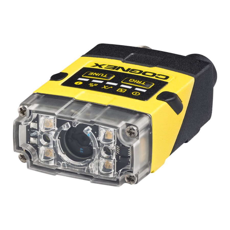
Page 14: Reader Layout
Getting Started Reader Layout The following images show the built-in lighting system and other features of the DataMan 150. Item Description Illumination LEDs LED aimers 3-4* Mounting holes (M3 x 3.5mm) Trigger button Power indicator Train status indicator Good/bad read indicator Communication Error indicator Tune button... -
Page 15: Changing Orientation
Getting Started Changing Orientation Perform the following steps to change between in-line and right-angle configuration. Note: Switching between in-line and right-angle configuration is recommended only up to 10 times in the lifetime of the DataMan 150. Disconnect the DataMan 150 from power before changing the orientation. WARNING: Make sure that no electrostatic charges are applied to the PCB. - Page 16 Getting Started Note: The flat side of the gasket (marked as "Front" in the image above) has to face outside. WARNING: Do not touch any electrical component. 4. Reattach the I/O connector module to the main module. 5. Reinstall the washers and loosely fasten the modules together with the two T10 cap nuts, but do not tighten.
-
Page 17: Dimensions
Getting Started 6. After each cap nut has been fastened, torque to 0.12 Nm (1.06 in-lb) and reinstall the screw covers. Note: There are unique left and right screw covers. Take care to attach them correctly. Dimensions The DataMan 150 consists of three main parts: 1. - Page 18 Getting Started Note: Dimensions are in millimeters [inches] and are for reference purposes only. All specifications are for reference purposes only and can change without notice. The size of the DataMan 150 in the angled configuration is shown in the following figure:...
-
Page 19: Dataman 150 Specifications
Getting Started DataMan 150 Specifications Specification DataMan 150 Series Reader Weight 128 g Operating 0ºC — +40ºC (+32ºF — +104ºF) Temperature Storage -10ºC — +60ºC (+14ºF — +140ºF) Temperature Maximum <95% (non-condensing) Humidity Environmental IP65 Shock and IEC 60068-2-27: 1000 shocks, semi-sinusoidal, 11g, 10ms... -
Page 20: Dataman 150 Series Imager Specifications
Getting Started DataMan 150 Series Imager Specifications Specification DataMan 150 Imager DataMan 152 Imager Image Sensor 1/3 inch CMOS 1/3 inch CMOS Image Sensor 4.51 mm x 2.88 mm (W x H), 6.0 μm square 4.8 mm x 3.6 mm (W x H), 3.75 μm square... -
Page 21: Led Wavelengths
Getting Started LED Wavelengths The following table shows LED types and the related wavelengths: λ [nm] RED HPIL BLUE WHITE 6500K (Color Temperature) IR HPIL Illumination Options Illumination 5V USB Powered PoE Powered 24V Externally Powered Board Max. exposure Max. duty Max. exposure Max. -
Page 22: Setting Up Your Dataman 150
Setting Up Your DataMan 150 Setting Up Your DataMan 150 This section provides information on the physical appearance of the DataMan 150 reader. It also details the steps of mounting the reader, installing the lenses and filters of the reader, describes tuning, and gives information on the imager itself. - Page 23 Setting Up Your DataMan 150 3. Push the top side of the filter firmly until it is sitting flat against the PCB. Note: Use finger to push the filter in and then a q-tip to clean the filter, or use a q-tip to push the filter into place.
-
Page 24: Installing A Liquid Lens
Setting Up Your DataMan 150 Installing a Liquid Lens Perform the following steps to install a liquid lens on your DataMan 150 reader. Note: Disconnect the DataMan 150 reader from power before installing the liquid lens. 1. Remove the front cover: unscrew the four M2x12mm Phillips Pan screws and take off the LED cover. 2. - Page 25 Setting Up Your DataMan 150 5. Attach the liquid lens accessory by aligning the 2x2 connectors of the liquid lens with the 2x2 sockets on the optics mount. 6. Press the liquid lens onto the imager lens until you reach the stop. 7.
-
Page 26: Changing A 6.2 Mm Lens To A 16 Mm Lens
Setting Up Your DataMan 150 Changing a 6.2 mm Lens to a 16 mm Lens Perform the following steps to change a 6.2 mm lens to a 16 mm lens on your DataMan 150 reader. Note: Disconnect the DataMan 150 reader from power before changing lenses. WARNING: This modification must be made in a dust-free and ESD safe area. - Page 27 Setting Up Your DataMan 150 4. Attach the 16 mm lens mount. 5. Fasten the two M2x5mm Phillips head screws to 0.06 Nm using a torque wrench. 6. In the case of a manual focus lens, press the 16 mm lens cap onto the lens. The lens has 12 cutouts so it can be locked in steps of 30 degrees.
-
Page 28: Changing To An Illumination With A Different Color
Setting Up Your DataMan 150 8. Attach the front cover. Observing the tightening sequence below, tighten all four M2x25 Phillips Pan head screws to 9 Ncm using a torque wrench. Note: The rib in the front cover must be oriented to the top side. Changing to an Illumination with a Different Color Perform the following steps to change the illumination. - Page 29 Setting Up Your DataMan 150 3. Attach a new color illumination module. Note: Take care to attach the illumination with the right orientation. 4. Attach the front cover. Observing the tightening sequence below, tighten all four screws to 9 Ncm using a torque wrench.
-
Page 30: Mounting
Setting Up Your DataMan 150 Mounting Mounting the DataMan 150 at a slight angle (15°) can reduce reflections and improve reader performance. Right-Angle Configuration... -
Page 31: Field Of View And Reading Distances
DataMan 150 Readers with a 6.2 mm Lens Short Range (Focused to 105 mm) The following map shows the FoV of the DataMan 150 series readers with a 6.2 mm lens. Outer FoV values refer to DM152, inner FoV values refer to DM150. - Page 32 Long Range (Focused to 190 mm) The following map shows the FoV of the DataMan 150 series readers with a 6.2 mm lens. Outer FoV values refer to DM152, inner FoV values refer to DM150. The following tables show the FoV widths of the 6.2 mm lens focused to 190 mm at various distances.
-
Page 33: Dataman 150 Readers With A 16 Mm Lens
DataMan 150 Readers with a 16 mm Lens The following map shows the FoV of the DataMan 150 readers with a 16 mm lens. Outer FoV values refer to DM152, inner FoV values refer to DM150 . The following tables show the FoV widths of the 16 mm lens at various distances. Device Distances in mm 2D min. -
Page 34: Connections, Optics And Lighting
Connections, Optics and Lighting Descriptions about the I/O Cables, RS-232 cable, flying leads cable, USB connections, digital input and output wiring, and multi- port connections are provided in the following sections. -
Page 35: Acquisition Triggering
Acquisition Triggering To trigger from an NPN (pull-down) type photo-detector or PLC output, connect Common In to +24VDC and connect In 0 to the output of the detector. When the output turns on, it pulls Common In down to 0VDC, turning the opto-coupler on. To trigger from a PNP (pull-up) type photo-detector or PLC output, connect to the output of the detector and connect to 0VDC. -
Page 36: Rs-232 Cable
RS-232 Cable You can connect a cable with RS-232 & flying leads (DM-RS232IO-00) to the cable that is attached to the device. The following table shows the pinout and color description of the flying leads. Color Signal Black Brown/White Blue/White Output-0 White Input-0... -
Page 37: Usb Connections
Color Signal Blue/White Output-0 White Input-0 White/Black Input-1 Light Blue Light Blue/Black Output-1 Light Blue/Yellow Output-Common Light Blue/Green Input-Common USB Connections When connected to a PC over USB, the DataMan 150 appears as a COM port. You can connect your device to the computer in the following ways: Connect directly to the PC: Connect to the PC through a basic I/O module: If the reader is configured as an HID device and you want to return to USB serial, scan the USB serial connection code:... -
Page 38: Rs-232 Connections
Note: The DataMan PC software must be installed for this connection type! RS-232 Connections You can connect the DataMan 150 reader to a PC or other device over a standard RS-232 serial connection. Note: You must supply external power to use this connection type. You can make a connection in the following ways: Connect directly to the PC: Connect to the PC through a basic I/O module:... - Page 39 1. Power: 5-24 VDC, 2.5W peak. Connect either ground pin to chassis ground. 2. Discrete output: Opto-isolated, current source or sink, depending on wiring; must connect logical ground to common. Outputs are opto-isolated and protected against reverse polarity. Max current is 50 mA @ 24 VDC. Output 1 is used for external illumination control by default.
-
Page 40: Digital Input Wiring Diagrams
Digital Input Wiring Diagrams Current Sink Configuration Current Source Configuration PNP Configuration... -
Page 41: Digital Output Wiring Diagrams
NPN Configuration Digital Output Wiring Diagrams The digital outputs can be used as either NPN (pull-down) or PNP (pull-up) lines. For NPN lines, the external load should be connected between the output and the positive supply voltage (<26V). The outputs pull down to less than 3V when ON, which causes current to flow through the load. - Page 42 Sinking Outputs, Sinking Inputs...
-
Page 43: Multi-Port Connections
Multi-port Connections You can connect multiple DataMan 150 readers to a single PC (or other device equipped with a serial port) using a multi-port connection. A multi-port connection creates a daisy-chain of readers. Each reader receives serial data from the previous reader and transmits it to the next reader. - Page 44 You must connect each DataMan 150 to DataMan Setup Tool using a USB connection and set the DataMan for multi- port operation. To configure a DataMan 150 for multi-port operation, click on the Enable Multi-Port (RS-232 Sharing) check box in Communication Settings. There is no guaranteed delivery order when multiple readers transmit data using a multi-port connection;...
- Page 45 If a DataMan 150 is transmitting its own read result, it will buffer any data received from another reader until it has finished its own data transmission. If a DataMan 150 is transmitting another reader’s data, it will buffer its own data if it receives a trigger signal while it is processing the other reader’s data.
-
Page 46: Using Your Dataman 150
3. Connect the DataMan 150 to your PC. 4. Choose Start > Programs > Cognex > DataMan Software vx.x.x > Setup Tool to launch the DataMan Setup Tool. Detected readers will appear under COM ports. 5. Click Refresh to update the list of connected devices. -
Page 47: Tuning
Using Your DataMan 150 2. Using a flathead screwdriver, set the focus position from the front. Always turn clockwise to focus to a larger distance and counterclockwise to focus to a shorter distance. Note: If an optical filter has been mounted, first disconnect the DataMan 150 reader from power and remove the illumination module with the filter before adjusting the focus. - Page 48 Using Your DataMan 150 Press the Tune button ( ) at least for 3 seconds on your reader. The first press starts the tuning and the second press cancels the tuning, if it is still ongoing. Turn on tuning in DataMan Setup Tool ( Start tuning by sending a DMCC, for more information, see the Command Reference, available through the Windows Start menu or the DataManSetup Tool Help menu.
-
Page 49: External Triggering And Trigger Modes
Using Your DataMan 150 External Triggering and Trigger Modes If you are using external triggering, you can use any of the following methods to trigger your DataMan 150 reader: 1. Press the Trigger button ( ) on the reader. 2. Send a pulse on Input-0 line. 3. -
Page 50: Training
Using Your DataMan 150 Training Training your reader with the expected symbology may help increase decode yield. To train your reader, place a code in front of the reader and do one of the following: Press and hold the trigger button ( ) for at least 3 seconds and the release it. -
Page 51: Incremental Training For Multiple Symbologies
Using Your DataMan 150 Incremental Training for Multiple Symbologies If you want to train the reader to recognize multiple symbologies, you can present a single image showing all the desired symbologies and perform the training procedure described in the previous section. If you cannot present a single image showing all the necessary symbologies, you can enable incremental training on the Training tab of the Symbology Settings page: With incremental training enabled, you can train the reader using multiple images showing the symbologies you expect... -
Page 52: Cleaning And Maintenance
Cleaning and Maintenance Cleaning and Maintenance Cleaning the Reader Housing To clean the outside of the reader housing, use a small amount of mild detergent cleaner or isopropyl alcohol on a cleaning cloth. Do not pour the cleaner directly onto the reader housing. CAUTION: Do not attempt to clean any DataMan product with harsh or corrosive solvents, including lye, methyl ethyl ketone (MEK) or gasoline. -
Page 53: Precautions
Precautions Precautions To reduce the risk of injury or equipment damage, observe the following precautions when you install the Cognex product: This device requires the use of an LPS or NEC class 2 power supply. Do not connect or disconnect this device from the I/O module or 15-pin USB adapter cable when the I/O module or adapter cable is connected to a PC. -
Page 54: Regulations/Conformity
Regulations/Conformity Regulations/Conformity The DataMan 150 Series has Regulatory Models 1AA3 and 1ABE and meets or exceeds the requirements of all applicable standards organizations for safe operation. However, as with any electrical equipment, the best way to ensure safe operation is to operate them according to the agency guidelines that follow. Please read these guidelines carefully before using your device. - Page 55 CB report available upon request. .TÜV SÜD, IEC/EN 61010-1. For European Community Users Cognex complies with Directive 2012/19/EU OF THE EUROPEAN PARLIAMENT AND OF THE COUNCIL of 4 July 2012 on waste electrical and electronic equipment (WEEE). This product has required the extraction and use of natural resources for its production. It may contain hazardous substances that could impact health and the environment, if not properly disposed.
- Page 57 Copyright © 2021 Cognex Corporation. All Rights Reserved.
Need help?
Do you have a question about the DataMan 150 Series and is the answer not in the manual?
Questions and answers