Table of Contents
Advertisement
Quick Links
Multi-Input HDBaseT Extender - 230 ft
STDHVHDBT
FR: Guide de l'utilisateur - fr.startech.com
DE: Bedienungsanleitung - de.startech.com
ES: Guía del usuario - es.startech.com
NL: Gebruiksaanwijzing - nl.startech.com
PT: Guia do usuário - pt.startech.com
IT: Guida per l'uso - it.startech.com
For the latest information, technical specifications, and support
for
this product, please visit www.startech.com/STDHVHDBT.
Manual Revision: 02/01/2017
*actual product may vary from
Advertisement
Table of Contents

Related Manuals for StarTech.com STDHVHDBT


Summary of Contents for StarTech.com STDHVHDBT
- Page 1 Multi-Input HDBaseT Extender - 230 ft STDHVHDBT *actual product may vary from FR: Guide de l’utilisateur - fr.startech.com DE: Bedienungsanleitung - de.startech.com ES: Guía del usuario - es.startech.com NL: Gebruiksaanwijzing - nl.startech.com PT: Guia do usuário - pt.startech.com IT: Guida per l’uso - it.startech.com For the latest information, technical specifications, and support this product, please visit www.startech.com/STDHVHDBT.
- Page 2 StarTech.com. Where they occur these references are for illustrative purposes only and do not represent an endorsement of a product or service by StarTech.com, or an endorsement of the product(s) to which this manual applies by the third-party company in question. Regardless of any direct acknowledgement elsewhere in the body of this document, StarTech.com hereby...
-
Page 3: Table Of Contents
Table of Contents Transmitter diagram ..................1 Front view ..............................1 Rear view ..............................1 Receiver diagram ....................2 Front view ..............................2 Rear view ..............................2 Introduction ......................3 Package contents ............................3 Requirements ............................. 3 Preparing your site ..................... 4 Installation ...................... -
Page 4: Transmitter Diagram
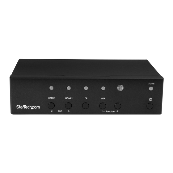
Transmitter diagram Front view 4. Function buttons 1. Selected port LEDs 2. Input selection buttons 5. Remote output LED 3. IR sensor 6. Local output LED 7. Output buttons Rear view 13 6 1. DC 12V power port 8. DP input port 2. -
Page 5: Receiver Diagram
Receiver diagram Front view 1. HDMI output 2. Status LED Rear view 1. DC power port 2. HDBaseT input port 3. Grounding bolt Instruction Manual... -
Page 6: Introduction
Introduction Package contents • 1 x multi-input HDBaseT extender switch (transmitter) • 1 x HDBaseT receiver • 1 x IR remote control • 1 x universal power adapter (NA, EU, UK, ANZ) • 2 x mounting brackets • 1 x RJ11-to-RS232 converter •... -
Page 7: Preparing Your Site
Note: The resolution performance of this extender switch will vary depending on the length of your cabling. Please review the chart below to determine the best solution for your setup. For best results, StarTech.com recommends shielded CAT6 cable. Distance Maximum resolution 35 m (115 ft.) or less... -
Page 8: Operation
Operation Mode selection and switch operation This HDBaseT switch features multiple operating modes. Review the description and operating steps for each mode in this section, then use the Mode switch to the set the HDBaseT switch to your desired operating mode. Switch mode operation (1. -
Page 9: Vga Screen Shifting
Manual operation with remote control 1. Press buttons 1 through 4 on the right side of the IR remote control to switch between the HDMI #1, HDMI#2, DisplayPort, and VGA ports respectively. 2. The active selected port LEDs will light up on the extender switch, indicating which port is selected, and your desired video source will appear on the HDMI and HDBaseT displays. -
Page 10: Set Edid
Set EDID When a video source is connected to a display, the display’s EDID is communicated to the video source. The display’s EDID is comprised of it’s video and audio capabilities. Displays sharing their EDID ensures optimal performance, by enabling the source to automatically align it’s video and audio settings to your display. -
Page 11: Manual Operation With Serial Control
Manual operation with serial control 1. Configure the settings on your serial port according to the values shown below. Baud Rate: 38400 bps Data Bits: 8 Parity: NoneCE= Stop Bits: 1 Flow control: None 2. Open your terminal software and configure it to communicate through the COM port that the switch is connected to. - Page 12 You can enter each of these commands into your terminal and press Enter to control every faucet of the extender switch. A general description of each primary command is listed in the table below. Primary command Action Value(s) required? codes Copies or emulates EDID to all connected video source devices.
- Page 13 If the command requires a value, the command will be listed in your terminal readout with =n next to it and a brief explanation of how the value should be utilized. If multiple values are required, the command is listed in your terminal readout with =n,a1,a2 If the command you’re entering requires a single value, the command needs to be modified to Command=Value1.
- Page 14 If you enter a value between 3 and 19 as your primary value, video EDID will be emulated based on the resolution that corresponds with the number you entered that’s listed in your terminal readout. Emulating a specific resolution requires second and third values.
-
Page 15: Led Indicators
LED indicators The transmitter and receiver included in this kit each have LED indicators that light up with different colors to notify you of the device status. The table below lists the activity for each of these LEDs as well as the corresponding status. Transmitter LEDs Activity Status... - Page 16 Receiver LEDs Activity Status Illuminates blue. The receiver has an active link with the transmitter. Status LED Illuminates blue flashes red. Receiver has power, but there is no active link with the transmitter. Instruction Manual...
-
Page 17: Technical Support
Limitation of liability In no event shall the liability of StarTech.com Ltd. and StarTech.com USA LLP (or their officers, directors, employees or agents) for any damages (whether direct or indirect, special, punitive, incidental, consequential, or otherwise), loss of profits, loss of business, or any pecuniary loss, arising out of or related to the use of the product exceed the actual price paid for the product. - Page 18 StarTech.com is an ISO 9001 Registered manufacturer of connectivity and technology parts. StarTech.com was founded in 1985 and has operations in the United States, Canada, the United Kingdom and Taiwan servicing a worldwide market.
Need help?
Do you have a question about the STDHVHDBT and is the answer not in the manual?
Questions and answers