
Subscribe to Our Youtube Channel
Related Manuals for AEMC 1020


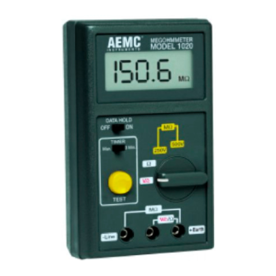
Summary of Contents for AEMC 1020
- Page 1 Megohmmeters Model 1020 Model 1025 Chauvin Arnoux, Inc. d.b.a. AEMC ® Instruments 99-MAN-100110 Rev 03 08/18...
- Page 2 Megohmmeters Model 1020 Model 1025 USER MANUAL MEGOHMMETER MODEL 1025 M Ω DATA HOLD MΩ TIMER Man. 3 Min. 500 V 250 V 1000 V Ω TEST MΩ /Ω - Line + Earth...
- Page 3 Owner’s Record The serial number for the Megohmmeter Model 1020 or Model 1025 is located on the back of the instrument. Please record this number and purchase date for your records. MEGOHMMETER MODEL 1020 CATALOG # 2111.91 SERIAL #: PURCHASE DATE:...
-
Page 4: Table Of Contents
Table of Contents Warning ..........2 International Electrical Symbols . -
Page 5: Warning
Always make connections from the instrument to the circuit under test. • The Megohmmeter Models 1020 and 1025 are sources of high voltage, as is the sample connected to them. All persons per- forming or assisting in the tests must employ all safety precau- tions to prevent electrical shock to themselves and to others. -
Page 6: Receiving Your Shipment
Description Model 1020 and Model 1025 are compact, light-weight, battery-oper- ated, digital megohmmeters. The Model 1020 tests at 250 V and 500 V up to 200 MΩ. The Model 1025 adds an additional voltage range of 1000 V, and measures up to 2000 MΩ. -
Page 7: Features
Models 1020/1025 Features • Model 1020 measures insulation at 250 and 500 V. • Model 1025 measures insulation at 250, 500, and 1000 V. • Continuity test • Continuity beeper • 600 V AC safety test voltage range • Large, easy-to-read digital display •... -
Page 8: Specifications
250 V and 500 V (Model 1020) 250, 500, 1000 V (Model 1025) Megohm Range: 0.1 to 200 MΩ (Model 1020 and 1025) 1 to 2000 MΩ (Model 1025 @ 1000 V) Resolution: 250 and 500 V : 0.1 MΩ... - Page 9 Operating Humidity: 0 - 80% RH Storage Humidity: 0 - 70% RH Dimensions: 6.5 x 3.9 x 2.2” (165 x 100 x 57mm) Weight: 1.1 lb (500 g) approx. *Accuracies are at 23° C ± 5° C, below 80% RH Megohmmeter Models 1020 and 1025...
- Page 10 Ω Ω Ω Ω Ω Figure 1 1. Digital Display 4. Press-to-Test Button 2. Data Hold Switch 5. Range Selector Switch 3. Manual and Lock Switch 6. Test Terminals (locks power on for 3 minutes) Megohmmeter Models 1020 and 1025...
- Page 11 /Ω - Line + Earth Figure 2 1. Digital Display 4. Press-to-Test Button 2. Data Hold Switch 5. Range Selector Switch 3. Manual and Lock Switch 6. Test Terminals (locks power on for 3 minutes) Megohmmeter Models 1020 and 1025...
-
Page 12: Safety Check/Voltage Test
No published standard tells which voltage to choose for any given winding. However, published recommendations are summarized as follows: Rated Voltage of Motor Test Voltage Below 115 250 V 250 V or 500 V 500 V 500 V or 1000 V Megohmmeter Models 1020 and 1025... -
Page 13: Spot Testing
Insulation resistance @ 30s This test is useful to increase the accuracy of spot testing. In gener- al, a ratio of 1.5 or better should be required. A ratio below this indi- cates that repair is probably needed. Megohmmeter Models 1020 and 1025... -
Page 14: For Successful Insulation Resistance Testing
Correct all readings properly to a standard reference temperature (see IEEE Std. #43-1974, Temperature Correction Curve). • Know what you are testing. Isolate the piece of equipment from other circuitry. • Watch trends rather than relying on single “spot” readings. Megohmmeter Models 1020 and 1025... -
Page 15: Insulation Measurement - Connections
Conductor Under Test Cable Insulation MEGOHMMETER MODEL 1025 M Ω DATA HOLD MΩ TIMER Man. 3 Min. 500 V 250 V 1000 V Ω TEST MΩ /Ω - Line + Earth – Figure 4 Megohmmeter Models 1020 and 1025... - Page 16 + Earth – Figure 5 Conductor Under Test Cable Insulation MEGOHMMETER MODEL 1020 Ω DATA HOLD MΩ TIMER Man. 3 Min. 500 V 250 V Ω TEST MΩ /Ω - Line + Earth – Figure 6 Megohmmeter Models 1020 and 1025...
- Page 17 TIMER Man. 3 Min. 500 V 250 V By removing the jumpers, read- Ω ings can be made between the TEST MΩ /Ω individual conductors - Line + Earth ground. – Figure 8 Megohmmeter Models 1020 and 1025...
-
Page 18: Insulation Resistance Measurements On Motors
By connecting the /Ω - Line + Earth megohmmeter as shown, the – phase insulation resistance value can now be determined. Read between phases “A” and “B”, then “B” and “C”, then “C” and “A”. Figure 10 Megohmmeter Models 1020 and 1025... -
Page 19: Continuity Measurements
Set the switch to the Ω position. Connect the red lead in the +earth position and the black lead in the middle jack position. MΩ /Ω - Line + Earth Figure 12 Megohmmeter Models 1020 and 1025... -
Page 20: Resistance Measurements
Figure 14 The instrument has a measurement range of 0.1 to 200Ω Connect the leads to the device under test. If an open circuit has been detected the display will read: HOLD Ω Figure 15 Megohmmeter Models 1020 and 1025... -
Page 21: Data Hold
Test is required, the user will have to hold down the test button and record the readings at 1 minute and 10 minutes. Insulation resistance @ 10 min = Polarization Index (PI) Insulation resistance @ 1 min Megohmmeter Models 1020 and 1025... -
Page 22: Maintenance
When battery voltage is not sufficient the low “BT” symbol will be dis- played. Remove the screw from the middle of the instrument and remove the back cover. Replace the 6 “AA” batteries. Reinstall the back cover and screw to secure the back cover. Megohmmeter Models 1020 and 1025... -
Page 23: Repair And Calibration
(North/South America, Australia, New Zealand) To guarantee that your instrument complies with the factory specifi- cations, we recommend that the Megohmmeter Models 1020 and 1025 be submitted to our factory service center at one year intervals for recalibration, or as required by other standards. -
Page 24: (Europe, Asia, Africa)
(Europe, Asia, Africa) To guarantee that your instrument complies with the factory specifi- cations, we recommend that the Megohmmeter Models 1020 and 1025 be submitted to our factory service center at one year intervals for recalibration, or as required by other standards. -
Page 25: Technical And Sales Assistance
Chauvin Arnoux 190, rue Championnet 75876 Paris Cedex 18 - France Tel: (33) 1 44 85 44 57 Fax: (33) 1 46 27 95 59 www.aemc.com Megohmmeter Models 1020 and 1025... -
Page 26: Limited Warranty
® What AEMC Instruments Will Do: If a malfunction occurs within the 2 year period, you may return the Megohmmeter Model 1020 or 1025 to us for repair or replacement free of charge, provided we have your ® REGISTRATION CARD on file. AEMC Instruments will, at its option, repair or replace the faulty material. - Page 27 NOTES Megohmmeter Models 1020 and 1025...
- Page 28 Megohmmeter Models 1020 and 1025...
Need help?
Do you have a question about the 1020 and is the answer not in the manual?
Questions and answers