Inspire ignite Installation Manual
Hide thumbs
Also See for ignite:
- Manual (17 pages) ,
- Installation manual (9 pages) ,
- User manual (7 pages)
Table of Contents
Advertisement
Quick Links
WARNING Electricity is dangerous. Before commencing work, ensure that you read and understand these
instructions and isolate the relevant circuit. This product should only be installed by a qualified electrician or
heating engineer and should be installed in accordance to BS 7671 (IEE Wiring Regulations), or to another
equivalent standard.
What's in the box
1 x Assembled Room Thermostat consisting of
1 x Room Thermostat
1 x Wall Mount
1 x Wall Blanking Plate
1 x Screw Pack
Introduction
The Ignite wired Thermostat is designed to replace an existing wired Thermostat in a
property. Please ensure your existing Thermostat has at least a 3 core cable.
If you do not have an existing wired Thermostat, you would need to run a cable, or consider
using our Ignite Wireless series. Once installed, your central heating can be switched on and
off in response to commands from the Thermostat or remotely using a computer or Smart
Phone.
Ignite Installation Guide Rev 1.0
1
Advertisement
Table of Contents

Related Manuals for Inspire ignite


Summary of Contents for Inspire ignite
- Page 1 If you do not have an existing wired Thermostat, you would need to run a cable, or consider using our Ignite Wireless series. Once installed, your central heating can be switched on and off in response to commands from the Thermostat or remotely using a computer or Smart...
-
Page 2: Specifications
Specifications Power Supply: 230V~ 50...60Hz Output: VoltFree or 230V Switch Type: 1 x SPST Switch Rating: 3 Amps Controllable Temperature Range: 10 – 30°C Frost Protection: Programmable from 0.5 30°C Radio Frequency: 2.4 GHz WiFi Dimensions: 103 x 103 x 45 mm (max) Radio Signal The Thermostat uses WiFi, so you need a WiFi signal where the Thermostat is located. - Page 3 Bad Positioning The below image shows the path that the signal will travel to communicate between the Router and Thermostat. This is an example of badly positioned items for the following reasons. The signal travels between 2 external walls. Good Positioning Simply by moving the router slightly to the right we have greatly improved the signal.
- Page 4 Installation Removal of your old Thermostat (if applicable) Ensure that your electrical supply is isolated, then remove your old Room Thermostat from the wall. Make a careful note of all wiring locations of the existing Thermostat before removing any wires. Note that the colour codes are not standard. These should be •...
- Page 5 Installing the Wall Mount For reliable operation, the Thermostat must mount correctly on the wall mount. If you have a single gang back box, secure the wall mount to this using the two M3 screws provided. If you do not have an existing back box then, using the wall mount as a template, mark the location of the two holes on the wall.
- Page 6 For guidance please refer to the wiring diagrams below, and/or the Wiring Conversions on page 7. Fig 5: Combi Boiler (Volt Free) Fig 6: Combi Boiler (230v) Fig 7: S Plan Fig 8: Y Plan...
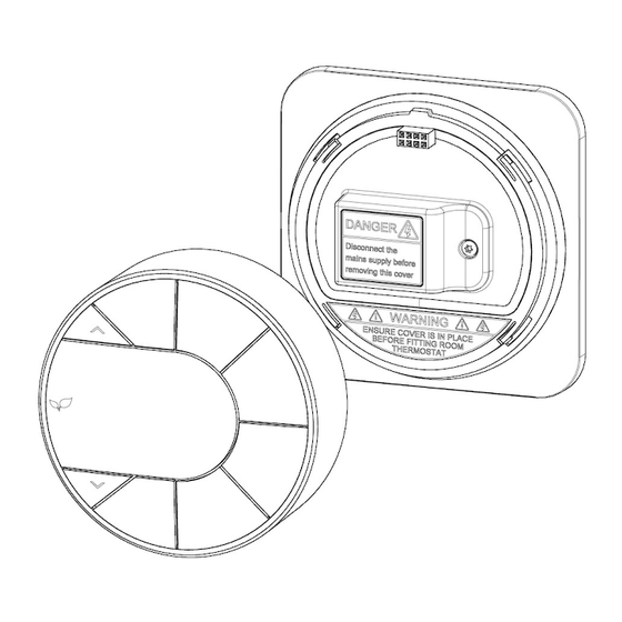
- Page 7 After the wiring has been completed, push the wiring cover into place and secure using the screw provided. (Fig 10) Finally place the Thermostat over the cover, this will click into place. (Fig 11) Wiring Conversions (more at www.inspirehomeautomation.co.uk/wiring.html) N L1 Ignite Danfoss RET 230/230F Link Link Danfoss TP1 Link...
-
Page 8: Testing The System
Testing the system If the central heating times were controlled by a programmer or timer (external or integrated into the boiler) and these are still wired into the system, these must be left switched to On or Continuous. The room containing the Thermostat must not have a Thermostat Radiator Valve (TRV) fitted to the radiator(s).
Need help?
Do you have a question about the ignite and is the answer not in the manual?
Questions and answers