Advertisement
ONLINE INSTALLATION VIDEOS
Scan this QR code, or visit...
https://inspirehomeautomation.co.uk/installation
For detailed installation instructions including video
tutorials, zoned systems (4ch), underfloor heating, FAQs and
fault finding guides.
Ignite - Touch
rev 1.0
Ignite Touch - 2ch,
Ignite Touch 4ch-1, 4ch-2, 4ch-3, 4ch-4
Ignite Hot Water
www.inspirehomeautomation.co.uk
Advertisement
Table of Contents

Related Manuals for Inspire Ignite - Touch 2ch Series


Summary of Contents for Inspire Ignite - Touch 2ch Series
- Page 1 ONLINE INSTALLATION VIDEOS Scan this QR code, or visit… https://inspirehomeautomation.co.uk/installation For detailed installation instructions including video tutorials, zoned systems (4ch), underfloor heating, FAQs and fault finding guides. Ignite - Touch rev 1.0 Ignite Touch - 2ch, Ignite Touch 4ch-1, 4ch-2, 4ch-3, 4ch-4 Ignite Hot Water www.inspirehomeautomation.co.uk...
-
Page 2: What's In The Box
WARNING Electricity is dangerous. Before commencing work, ensure that you read and understand these instructions and isolate the relevant circuit. This product should only be installed by a qualified electrician or heating engineer and should be installed in accordance to BS 7671 (IEE Wiring Regulations), or to another equivalent standard. -
Page 3: Specification
INTRODUCTION The Ignite - Touch 2ch series is designed to control a typical domestic central heating system. The system can switch two independent channels, Central Heating and Hot Water (if applicable). The Ignite - Touch 4ch series is designed to control a zoned domestic central heating system. -
Page 4: Radio Signal
RADIO SIGNAL Only Applicable for Wireless Install… Consideration for the location of your Thermostat and Receiver, and the affect that this may have on the radio signal is extremely important. The signal will travel between units in a straight line and will degrade both with distance and (much more importantly) objects that it has to pass through. - Page 5 LOCATION As shown in Fig 2, ideally the Thermostat should be mounted on an internal wall at a height of 1 .5m and in a high traffic area. Avoid locating near draughts such as the front door or windows. Do not position above heat sources and avoid direct sunlight.
-
Page 6: Installation
INSTALLATION Before commencing work, please consider if you will be installing the system as Wired or Wireless. If installing the thermostat as Wired, please refer to page 14 before commencing installation. Both Wired and Wireless installation requires the Receiver. The Receiver can be installed anywhere in the property providing you are able to run cables, this can help improve RF signal connection strength. - Page 7 Usually, there will be a wire link to remove on the boiler terminal block, then these two terminals are wired to terminals 3 & 4 on the Inspire Terminal board as shown in Fig 5. Connect the Receiver Live(L) and Neutral(N) to the same fused spur as the boiler.
- Page 8 The majority of combi boilers can be wired using the 4 wire installation method. If your boiler manual suggests a 3 wire install, then refer to Fig 6, remembering to remove the link wire in the boiler (if required) and add a link wire between terminals 4 &...
- Page 9 SYSTEM BOILER WITH EXISTING CONTROLS System Boiler with existing 2 channel programmer and optional Thermostat **Before commencing, take clear photos of the existing programmer wiring** S Plan (2 x 2 port zone valves, usually near hot water cylinder) Usually 4 Wires to existing programmer, Live, Neutral, CH ON, HW ON. (CH OFF and HW OFF not used) Y plan (1 x 3 port zone valve, usually near the hot water cylinder) Usually 5 wires to existing programmer, Live, Neutral, CH ON, HW ON, HW OFF.
- Page 10 Install the previously identified wires into the appropriate terminals (see Fig 8). As an example, the black wire in terminal 4 of the old programmer is identified as "CH ON" from the existing programmer schematic. This would go into terminal 3 "CH ON"...
- Page 11 SYSTEM/COMBI BOILER WITH EXISTING CONTROLS **Before commencing, take clear photos of the existing programmer wiring** A multi zone setup will usually be wired as an “S Plan Plus” (One 2 port zone valve per zone, usually near the hot water cylinder or boiler) There will be 2 wires for power and 1 additional wire per zone to the existing programmer.
- Page 12 3. You would transfer zones 1 & 2 to CH1 and CH2, but zone 3 (The hot water zone) would be moved to CH4/HW in the inspire system. CH3 in this case would not be used.
- Page 13 INSTALLATION - RECEIVER If you have a single gang back box, secure the receiver to this using two of the M3.5 screws provided. If you do not have an existing back box, use the receiver as a template and mark the location of the two holes on the wall.
- Page 14 Wired Installation Remove the batteries from the rear of the Thermostat. These are not required. Using new, or existing cabling, ensure there is 10mm of exposed copper at the Thermostat and 8mm at the Receiver. Connect S1 and S2 Fig 14 on the Thermostat (see Fig 14) to S1 and S2 on the Receiver (see Fig 15).
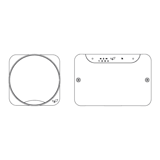
- Page 15 IGNITE TOUCH THERMOSTAT Fig 16 IGNITE TOUCH RECEIVER Fig 17...
-
Page 16: Testing The System
Tools -> Register Thermostat from within the app. Or scan the QR code at the front of the manual for further assistance. Important You will need to be in the same location as the inspire system to complete the initial setup.
Need help?
Do you have a question about the Ignite - Touch 2ch Series and is the answer not in the manual?
Questions and answers