Scania DC09 Installation Manual
Exhaust system
Hide thumbs
Also See for DC09:
- Operator's manual (120 pages) ,
- Installation manual (59 pages) ,
- Installation manual (44 pages)

Related Manuals for Scania DC09


Summary of Contents for Scania DC09
-
Page 1: Exhaust System
INSTALLATION MANUAL Exhaust system Industrial engines DC09, DC13, DC16 01:04 Issue 10 en-GB © Scania CV AB 2016, Sweden... -
Page 2: Table Of Contents
Insulation of SCR components................25 Insulation of Stage IV/Tier 4f engines .............. 25 Protection against water ingress ................27 Multi-engine installation..................28 Dimensioning the exhaust system ................ 30 Calculation example..................31 01:04 Issue 10 en-GB © Scania CV AB 2016, Sweden... -
Page 3: Sound Reduction
63 and 125 1,800 and 2,100 80 and 160 DC13 257-316 1,500 80 and 160 1,800 and 2,100 100 and 200 331-405 1,500 80 and 160 1,800 and 2,100 100 and 200 01:04 Issue 10 en-GB © Scania CV AB 2016, Sweden... - Page 4 This phenomenon occurs higher up in the frequency range and is effectively dampened with an absorption silencer (e.g. glass fibre). Vibrations in the silencer casing can also generate noise. For this reason, avoid si- lencers with flat surfaces. 01:04 Issue 10 en-GB © Scania CV AB 2016, Sweden...
-
Page 5: Exhaust System Design
The exhaust gases contain soot particles so there is also a risk of the air filter becoming blocked. WARNING! Position the exhaust outlet so that exhaust gases cannot penetrate areas occupied by people, e.g. residential buildings. 01:04 Issue 10 en-GB © Scania CV AB 2016, Sweden... - Page 6 The installer is responsible for ensuring that the exhaust system is well sealed during installation. He is also responsible for ensuring that the pipe and silencer suspension is designed in such a way that system leaks cannot arise during operation. 01:04 Issue 10 en-GB © Scania CV AB 2016, Sweden...
- Page 7 Examples of short exhaust systems with designs which aid sound reduction. L = Length of tailpipe, determined from graph. a = 2/3 of L. Length a is less significant in exhaust systems with only one silencer. 01:04 Issue 10 en-GB © Scania CV AB 2016, Sweden...
- Page 8 The oxidation catalytic converter provides a sound reduction of approximately 1.5 dB from 500 Hz and higher frequencies. At lower frequencies, the oxidation cat- alytic converter has no sound reducing effect. 01:04 Issue 10 en-GB © Scania CV AB 2016, Sweden...
-
Page 9: Connection Of Exhaust System To Engine
A flexible connection can consist of the Scania exhaust bellows. Position the flexible connection as close to the turbocharger con- nection as possible. -
Page 10: Stage Iii B/Tier 4I And Less Restrictive Emission Laws
The exhaust pipe bend is connected to the turbocharger with a V-clamp. The exhaust pipe bend outlet has a flange that is connected with a V-clamp. It is usu- ally connected directly to the Scania exhaust bellows. Ø185.3 Ø185.3 Exhaust pipe bends for DC09 and DC13 DC09 071A. - Page 11 Ø185,3 Ø185,3 DC16 071A. Weld flanges for connection to turbocharger Weld flange for DC09 and DC13 072/073A, is connected using V-clamp with part number 1 433 190. Ø125 Weld flange for DC13 and DC16, connected using V-clamp with part number Ø102...
- Page 12 MANUAL Connection of exhaust system to engine Exhaust bellows The Scania exhaust bellows consists of 2 flexible sections with several layers of cor- rugated stainless steel plate that are connected to a short pipe. The exhaust bellows 20 mm 20 mm can absorb both longitudinal and lateral movements.
- Page 13 3 different inside diameters (A): 114, 130 and 155 mm. The weld flange is made from stainless steel. Ø140 Connect the flange to the SCR catalytic converter using the V-clamp with part num- Ø123 ber 1 863 832. 20° 01:04 Issue 10 en-GB © Scania CV AB 2016, Sweden...
- Page 14 The exhaust system should be fitted so that there are no stresses in the system. Tight- en the V-clamp after the engine has warmed up to working temperature for the first time. 01:04 Issue 10 en-GB © Scania CV AB 2016, Sweden...
- Page 15 The exhaust system should be fitted so that there are no stresses in the system. Tight- en the V-clamp after the engine has warmed up to working temperature for the first time. V-clamp. Exhaust brake. Hydraulic cylinder. Connection for hydraulic oil pipe. Bracket. 01:04 Issue 10 en-GB © Scania CV AB 2016, Sweden...
-
Page 16: Stage Iv/Tier 4F
A = Ø 114, 130 or 155 mm. Ø 114 does not apply to DC16. Weld flange for connection to exhaust brake The weld flange for connection to the exhaust brake is available to DC09 and DC13. It is secured using the V-clamp with part number 1 863 831. - Page 17 Scania has 2 different types of exhaust bellows for Stage IV/Tier 4f engines: 20˚ Exhaust bellows for connection to the exhaust brake. This exhaust bellows is only available to DC09 and DC13. On DC13 085A, the exhaust bellows can be connected to the exhaust pipe downstream of the turbocharger. 20˚...
-
Page 18: Exhaust Back Pressure
If the exhaust back pressure is above the maximum recommended exhaust back pres- sure, this has a negative impact on engine performance. REQUIREMENT! Check the exhaust back pressure when installation is complete. 01:04 Issue 10 en-GB © Scania CV AB 2016, Sweden... -
Page 19: Exhaust Back Pressure Stage Iii B/Tier 4I
Basic exhaust back pressure (mbar) Maximum recommended exhaust back pressure (mbar) DC09 DC13 DC16 1. Exhaust back pressure for evaporators or hydrolysis catalytic converters and SCR catalytic converters is included. 01:04 Issue 10 en-GB © Scania CV AB 2016, Sweden... -
Page 20: Exhaust Back Pressure For Stage Iv/Tier 4F
1,800 DC13 2,100 2,100 2,100 1,900 1,800 1,800 2,100 DC16 2,100 2,100 2,100 2,100 1. Exhaust back pressure for any oxidation catalytic converter, evaporator and SCR catalytic converter is included. 01:04 Issue 10 en-GB © Scania CV AB 2016, Sweden... -
Page 21: Measuring Exhaust Back Pressure
See the illustration. Measuring exhaust back pressure on engines with SCR system without oxidation cat- alytic converter. Evaporator or hydrolysis catalytic converter. Suitable point for measuring exhaust back pressure. Exhaust bellows. Turbocharger. 01:04 Issue 10 en-GB © Scania CV AB 2016, Sweden... - Page 22 See the illustration. Measuring exhaust back pressure on engines with SCR system and engine-mounted oxidation catalytic converter. Oxidation catalytic converter. Suitable point for measuring exhaust back pressure. Exhaust brake. 01:04 Issue 10 en-GB © Scania CV AB 2016, Sweden...
- Page 23 (a) of the water in the hose. This is a direct measurement of exhaust back pressure in mmH O. 1,000 mmH O is equal to 100 mbar. Example of exhaust back pressure measurement. Pipe. Plastic hose. 01:04 Issue 10 en-GB © Scania CV AB 2016, Sweden...
-
Page 24: Insulating The Exhaust System
The insulation must be designed so that the flexible part of the exhaust system is not restricted in its movement. It must also be possible to inspect the exhaust system without damaging the insulation during dismantling. 01:04 Issue 10 en-GB © Scania CV AB 2016, Sweden... -
Page 25: Insulation Of Scr Components
5 mm thick- ness and wind protection. The insulation protects the SCR system against impact of the external environment. Scania offers insulation as an option for the evaporator and the oxidation catalytic converter. IMPORTANT! The exhaust bellows for connection to the exhaust brake must not be insulated. - Page 26 Note: The temperature drop must be checked by running the engine at a constant exhaust mass flow during a minimum of 10 minutes. Exhaust mass flow is measured using SDP3. 01:04 Issue 10 en-GB © Scania CV AB 2016, Sweden...
-
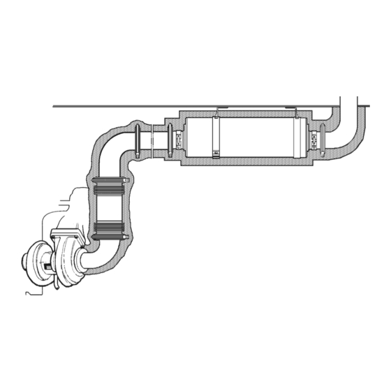
Page 27: Protection Against Water Ingress
A drainable water trap must also be connected to the condensation separator. Device for protecting against water ingress. V-clamp. Silencer. Connecting flange. Gasket. Condensation separator. Bracket. Flexible connection (exhaust bellows). Engine. Exhaust pipe bend. 01:04 Issue 10 en-GB © Scania CV AB 2016, Sweden... -
Page 28: Multi-Engine Installation
If the engines are of different types, calculate the diameter of the common pipe (d d gem = 3,14 gem) using the formula on the right. Formula for calculating the diameter with different engine types. 01:04 Issue 10 en-GB © Scania CV AB 2016, Sweden... - Page 29 There is also a risk that the exhaust gases could enter the engine compartment. 01:04 Issue 10 en-GB © Scania CV AB 2016, Sweden...
-
Page 30: Dimensioning The Exhaust System
Select the next higher standard diameter. • If corrugated hose is used for a large part of the system, the dimension must be increased by at least 10 %. 01:04 Issue 10 en-GB © Scania CV AB 2016, Sweden... -
Page 31: Calculation Example
Additional length (Lt): 12 m, refer to graph for calculating additional length. Ltot (for calculating final diameter): Lu + Lt = 32 m, rounded to 30 m. Read the final inside diameter for DC09 078A = 130 mm. Refer to the table ex- ample from Technical below below. - Page 32 Graph for calculating additional length in exhaust system From the calculation example: • Preliminary inside diameter (Dp) = 125 mm • Number of bends = 6 • Additional length (Lt) = 12 m Dp(mm) 01:04 Issue 10 en-GB © Scania CV AB 2016, Sweden...
Need help?
Do you have a question about the DC09 and is the answer not in the manual?
Questions and answers