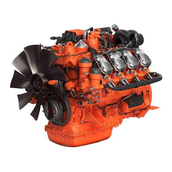
Scania DC09 Installation Manual
Fuel system
Hide thumbs
Also See for DC09:
- Operator's manual (120 pages) ,
- Installation manual (59 pages) ,
- Installation manual (17 pages)
Summary of Contents for Scania DC09
-
Page 1: Fuel System
INSTALLATION MANUAL Fuel system Industrial engines DC09, DC13, DC16 01:03 Issue 6.1 en-GB © Scania CV AB 2016, Sweden... -
Page 2: Table Of Contents
PDE engines ...................... 16 Flow and pressure ....................17 XPI engines ....................... 17 PDE engines ...................... 17 Risk of fire ......................18 Fuel grade and power for PDE engines............... 19 01:03 Issue 6.1 en-GB © Scania CV AB 2016, Sweden... -
Page 3: Fuel Tank
Ventilating valve Example of a fuel system for a stationary industrial engine 3-way valves Feed pump Hand pump Inspection hatch Fuel gauge Overfill protection Filler cap Main tank Drain tap 01:03 Issue 6.1 en-GB © Scania CV AB 2016, Sweden... -
Page 4: Position
If the tank(s) are built in, the space should be well ventilated. 01:03 Issue 6.1 en-GB © Scania CV AB 2016, Sweden... - Page 5 IMPORTANT! Fitting an extra water separating fuel filter in addition to the Scania prefilter is not permitted on the fuel pipe to the engine. 01:03 Issue 6.1 en-GB ©...
-
Page 6: Fuel Tank Design
By law, the label "Ultra Low Sulfur Fuel Only" must be affixed at the filler cap on all engines certified in accordance with Tier 4. The label is supplied with all indus- trial engines from Scania. 01:03 Issue 6.1 en-GB © Scania CV AB 2016, Sweden... - Page 7 Power correction due to increase in fuel temperature is displayed in the tables in the section Fuel grade and engine power. 01:03 Issue 6.1 en-GB © Scania CV AB 2016, Sweden...
-
Page 8: Main Tank And Buffer Tank
• Tanks which are buried should have a drain pipe from the bottom to lead away sludge and water. See instructions in the Fuel tank design section for further details. 01:03 Issue 6.1 en-GB © Scania CV AB 2016, Sweden... -
Page 9: Fuel Pipes
In multi-engine installations, the fuel system should be divided into at least two in- dependent systems so that a fault in one of the fuel lines does not cause all engines to stop. 01:03 Issue 6.1 en-GB © Scania CV AB 2016, Sweden... - Page 10 The minimum inside diameter of the fuel suction line is shown in the table below. Fuel pipe length Shorter than 3 m Longer than 3 m Engine type Inner diameter (mm) Inner diameter (mm) DC09 DC13 DC16 PDE DC16 XPI 01:03 Issue 6.1 en-GB © Scania CV AB 2016, Sweden...
-
Page 11: Fuel Filter
XPI engines DC09 and DC13 On DC09 and DC13 XPI, the water separating prefilter is fitted on the engine on de- livery. The connections on this filter and on the main filter are described on the right. Fuel filter for DC09 and DC13 XPI... - Page 12 Fuel return to prefilter 12 mm Suction hose for water separation from prefilter 6 mm In to feed pump 16 mm Return to fuel tank 12 mm Fuel filter for DC16 XPI. 01:03 Issue 6.1 en-GB © Scania CV AB 2016, Sweden...
-
Page 13: Pde Engines
The prefilter should not be installed higher than the feed pump, because that results in an unnecessarily high suction height, making the engine more difficult to start. If Scania's standard filter is not used, a prefilter of maximum 10 micrometres is rec- ommended. -
Page 14: Fuel Heater For Xpi Engines
Material: Connector 2-pin DTP: 1 907 302 (DTP06-2S-CE09) with shrinking tubing adapter (Boot adapter). Locking part: 1 507 728 (WP2S). Cable terminal x 2: 1 507 723 (1062-12-1066) 2-4 mm 01:03 Issue 6.1 en-GB © Scania CV AB 2016, Sweden... - Page 15 INSTALLATION MANUAL Fuel heater for XPI engines Shrinking tubing between connector and cable: Raychem type HTAT, size 24/6. 01:03 Issue 6.1 en-GB © Scania CV AB 2016, Sweden...
-
Page 16: Feed Pump Flow Rates
The feed pump flow rates shown in the diagram apply at normal working pressure. PDE engines The feed pump flow rates shown in the table apply at normal working pressure (4-6 bar). Engine speed (rpm) Feed pump flow for DC09, DC13, DC16 (l/hr) 1000 1500 1800... -
Page 17: Flow And Pressure
An overflow valve with an opening pressure of approx. 6 bar is fitted on the fuel manifold. It ensures that the feed pump is always filled with fuel, which ensures that the engine can start. 01:03 Issue 6.1 en-GB © Scania CV AB 2016, Sweden... -
Page 18: Risk Of Fire
• Be careful when filling the fuel tank with fuel. If the fuel tank is close to the en- gine, the engine should be switched off and allowed to cool. WARNING! Heated diesel constitutes a risk of explosion! 01:03 Issue 6.1 en-GB © Scania CV AB 2016, Sweden... -
Page 19: Fuel Grade And Power For Pde Engines
The read corrected engine powers as a percentage from the figures must first be add- ed together to obtain the final corrected engine power. Multiply this with Scania's specified engine power to obtain the corrected engine power in kW. Then add or sub- tract from Scania's specified engine power to obtain the corrected engine power with- in the given tolerances. - Page 20 Engine power dependence on density of fuel. Normal Engine power dependence on temperature of fuel. The value is 3 cSt at 40°C value is 0.84 kg/dm³ at 15°C reference temperature is 35°C 01:03 Issue 6.1 en-GB © Scania CV AB 2016, Sweden...


Need help?
Do you have a question about the DC09 and is the answer not in the manual?
Questions and answers