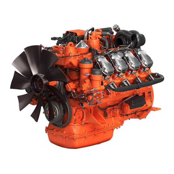
Scania DC09 Installation Manual
Hide thumbs
Also See for DC09:
- Operator's manual (120 pages) ,
- Installation manual (59 pages) ,
- Installation manual (52 pages)
Advertisement
Table of Contents
Advertisement
Table of Contents

Summary of Contents for Scania DC09
- Page 1 INSTALLATION MANUAL Intake system and ventilation Industrial engines DC09, DC13, DC16 01:02 Issue 6 en-GB © Scania CV AB 2014, Sweden...
-
Page 2: Table Of Contents
Crankcase ventilation.................... 11 Open crankcase ventilation ................11 Closed crankcase ventilation................12 Connection to turbocharger ................. 13 Cleanliness requirement ..................13 Charge air pipe ....................13 Stage IV/Tier 4f engines ................... 14 01:02 Issue 6 en-GB © Scania CV AB 2014, Sweden... -
Page 3: Intake Air
A = Engine power indicated in the tables showing the air consumption and radiated heat for the relevant B = Intake air temperature engine type under Technical data in the Installation manual. 01:02 Issue 6 en-GB © Scania CV AB 2014, Sweden... -
Page 4: Intake Air Taken From Outside Engine Compartment
The air intake should be designed to exclude water, snow and contamination. Maximum permissible pressure drop is 30 mbar. This value includes the pressure drop in the new air filter, connected coarse filter and in the fresh air line. 01:02 Issue 6 en-GB © Scania CV AB 2014, Sweden... - Page 5 It is not necessary to check the pressure drop in the following cases: • The intake system comprises air hoses and air pipes from Scania's standard range. • If the fresh air line is maximum 5 m and has an inside diameter of at least 160 mm for DC09 or 210 mm for DC13 and DC16, respectively.
- Page 6 The amount of radiated heat emitted by various engines is indicated under Technical data in the Installation manual. The exhaust pipes should be insulated to reduce the radiated heat in the engine com- partment. See Exhaust system in the Installation manual. 01:02 Issue 6 en-GB © Scania CV AB 2014, Sweden...
-
Page 7: Intake Air Taken From Engine Compartment
The heat radiation depends on how much of the line is inside the engine compartment and how much of it is insulated. There is also additional heat due to efficiency losses in driven units located in the en- gine compartment. 01:02 Issue 6 en-GB © Scania CV AB 2014, Sweden... -
Page 8: Air Cleaners
An effective self-cleaning prefilter is recommended for particularly dusty environ- ments. Even engine systems exposed to driving snow can require a special type of prefilter. 01:02 Issue 6 en-GB © Scania CV AB 2014, Sweden... -
Page 9: Air Cleaners With Precleaner
It is also important to make sure that any insulation in the engine compartment and around the exhaust pipes cannot come loose and be drawn into the intake line. If a non-Scania air filter is used, engine air consumption and filter element pore size must be considered. -
Page 10: Air Cleaners Without Precleaner
The air cleaner must be fitted horizontally with the air intake (1) pointing down- wards. The air cleaner may also be fitted vertically, but only if it is fitted indoors or in such a way that water cannot get into the air filter. 01:02 Issue 6 en-GB © Scania CV AB 2014, Sweden... -
Page 11: Crankcase Ventilation
• If pipe is used, there should be a flexible, oil-resistant line between the engine and pipe to absorb the engine movements. Open crankcase ventilation, DC16 • If hose is used, it must be clamped so that no sharp kinks are formed. 01:02 Issue 6 en-GB © Scania CV AB 2014, Sweden... -
Page 12: Closed Crankcase Ventilation
It is not permissible to lead the crankcase gases to the intake upstream of the engine air filter. Closed crankcase ventilation A. DC09, DC13 B. DC16 01:02 Issue 6 en-GB © Scania CV AB 2014, Sweden... -
Page 13: Connection To Turbocharger
Do not remove the protection from the turbocharger inlet pipes and charge air pipe before they are connected. Charge air pipe The installation of the charge air pipe recommended by Scania is shown in the illus- tration. IMPORTANT! Position a flexible hose as close to the turbocharger connection as possible to reduce forces and torques. -
Page 14: Stage Iv/Tier 4F Engines
Stage IV/Tier 4f engines Inlet pipe for connection to turbocharger The Scania inlet pipes for connection to the turbocharger must be used on all engines certified according to Stage IV/Tier 4f. The inlet pipes are available in 2 different versions for DC09 and DC13, and in 1 version for DC16. - Page 15 T126. The mass flow sensor pipes are available in 2 different versions for DC09 and DC13, and in 1 version for DC16. The dimensions and air direction for the mass flow sensor pipes are shown in the il- lustrations below.
- Page 16 • Use hose which is sturdy enough so that it does not collapse onto itself. Tightening torque for hose clamps: 5 Nm. Maximum distance between the inlet pipe and mass flow sensor pipe 01:02 Issue 6 en-GB © Scania CV AB 2014, Sweden...
- Page 17 ±90°. The airflow must hit the measuring body of the mass flow sensor (1). The relationship between the pipe bend and mass flow sensor pipe if a pipe bend is installed upstream of the mass flow sensor pipe 01:02 Issue 6 en-GB © Scania CV AB 2014, Sweden...


Need help?
Do you have a question about the DC09 and is the answer not in the manual?
Questions and answers