
Subscribe to Our Youtube Channel
Related Manuals for Magnetrol F10


Summary of Contents for Magnetrol F10
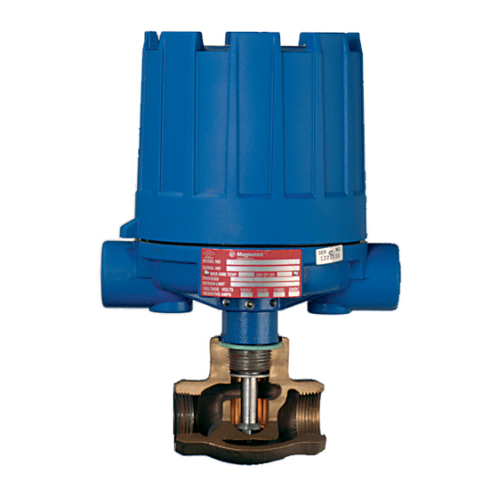
- Page 1 Models F10 and F50 Installation and Operating Manual Switches Model F10 Model F50...
- Page 2 MAGNETROL will repair or replace the control at no cost to the purchaser (or owner) other than transportation. W RNINGS...
-
Page 3: Table Of Contents
1.1.1 Model F10...........4 4.2 Agency Approvals ..........14 1.1.2 Model F50...........4 4.3 Specific Gravity ...........15 1.2 Operating Cycle ............4 4.3.1 Model F10 and F50 Specific Gravity Correction ..........15 1.2.1 Model F10...........4 4.4 Specifications............16 1.2.2 Model F50...........5 4.4.1 Model F10 Actuating Flow Rates ....16 2.0 Installation ..............5... -
Page 4: Introduction
Introduction 1.0.1 Model F10 F10 vane-actuated flow switches provide excellent reliabili- ty for a broad spectrum of horizontal pipe flow-sensing applications, including air, oil and petroleum derivatives, corrosive chemicals, and water. 1.0.2 Model F50 Adjusting Pivot screw F50 Flow Switches are utilized, in horizontal lines, to sense... -
Page 5: Model F50
(magnetic) Swing in position 2.2.1 Model F10 The F10 flow switch should be located in a horizontally run pipe with the arrow on the body bushing or mounting Flow disc flange pointing in the direction of flow. 2.2.2 Model F50 Figure 4—Position w/Actuating... -
Page 6: Mounting
2.62-inch (67 mm) dimension and four places use inside of threadolet as template. 2.62 (67) 5. Proper operation of the F10 depends upon the vertical dia. center line of the 2" NPT coupling being plumb within (See Note following 3°. -
Page 7: Trimming Vane To Fit Horizontal Line Size
The F10 is furnished as standard with vanes suitable for Vane support bracket use on 2-inch through 30-inch pipelines. Assemble vane mounting screws (3) (or vanes) to F10 and trim according to applicable line size Top of 2" Pivot pin threadolet... -
Page 8: Model F10 - Flanged Connection
➁ Flange to match flange of F10 flow switch and tube at two places, 90 degrees apart. positioned with bolt holes straddling center lines. -
Page 9: Model F10 Switch Actuation Adjustment
6. Place flow switch into service. 2.4.1 Model F10 Switch Actuation Adjustment The F10 flow switch is factory set to actuate at the mini- mum flow rate. Actuation flow rate can be increased while the unit is in service, under pressure, by removing the ⁄... -
Page 10: Preventive Maintenance
On units with pneumatic switches, air (or gas) operating medium lines, subjected to vibration, may eventually crack or become loose at connections causing leakage. Check lines and connections carefully and repair or replace, if necessary. 47-602 F10 and F50 Flow Switches... -
Page 11: Inspect Entire Unit Periodically
A sufficient amount of lubricant has been applied at the factory to ensure a lifetime of service. Further lubrication is unnecessary, and will only tend to attract dust and dirt which can interfere with mechanism operation. 47-602 F10 and F50 Flow Switches... -
Page 12: Reference Information
NOTE: As a matter of good practice, spare switches should be kept on hand at all times. If switch mechanism is operating satisfactorily, a test of the complete control’s performance is the next likely step. 47-602 F10 and F50 Flow Switches... -
Page 13: Test Control's Performance
Check for malfunctioning by manually moving magnet carriage. If all components in the unit are in operating condition, the trouble must be located external to the unit. Repeat inspection of external conditions previously described. 47-602 F10 and F50 Flow Switches... -
Page 14: Agency Approvals
< 100 °C < 135 °C < 200 °C < 300 °C < 450 °C These units are in conformity with IECEx KEM 05.0020X Classification Ex d IIC T6 T ambient -40 °C to +70 °C 47-602 F10 and F50 Flow Switches... -
Page 15: Specific Gravity
Specific Gravity 4.3.1 Model F10 and F50 Specific Gravity Correction To determine the actuating flow rates for liquids other than Example: The maximum adjustment for an increasing flow water (approximate viscosity of 20 centistokes or less), a rate with a liquid specific gravity of .70 in an 8"... -
Page 16: Specifications
Specifications 4.4.1 Model F10 Actuating Flow Rates Water Service Model F10 units may be adjusted in service to actuate within the minimum and maximum flow rates given below. A specific gravity correction factor is applied for liquids other than water. - Page 17 4.4.1 Model F10 Actuating Flow Rates (cont.) Water Service m Model F10 units may be adjusted in service to actuate within the minimum and maximum flow rates given below. A specific gravity correction factor is applied for liquids other than water (1.00 specific gravity).
-
Page 18: Model F50 Actuating Flow Rates
2.3 dec. 4.0 dec. 6.5 dec. 10.5 dec. 17.9 dec. 2" 1.9 inc. 3.1 inc. 5.1 inc. 8.4 inc. 14.3 inc. 24.8 inc. 1.6 dec. 2.7 dec. 4.3 dec. 7.1 dec. 12.1 dec. 21.0 dec. 47-602 F10 and F50 Flow Switches... -
Page 19: Model F10 Dimensional Specifications
NEMA 1 — 8.00 (203) 7.38 (187) NEMA 4X/7/9 — 10.00 (254) Top of pipe run Standoffs (Qty. 3) Group B — 10.00 (254) 3.00 (76) Diameter 0.19 (5) Minimum Flow Vane F10 with Flanged Connection 47-602 F10 and F50 Flow Switches... -
Page 20: Model F50 Dimensional Specifications
HS hermetically sealed switch with terminal block 2.00 Horizontal (25) lines only 5.75 (1.46) F50 Flow Switch with 1 ⁄ " or 2" NPT Internal Pipe, Bronze or Stainless Steel Body 47-602 F10 and F50 Flow Switches... -
Page 21: Replacement Parts
O-ring Adjustment screw Enclosing tube Enclosing tube gasket Body bushing or stem, cam follower & flange assy. Flow arrow Figure 11 — F10 with Flange Connection Upper spring guide Range spring 10-32 hex nut Lower spring guide Attraction sleeve Washer... -
Page 22: Model F10 Threaded Mounting
032-7205-002 600 lb. 032-7203-003 032-7204-003 032-7205-003 Attraction sleeve and spring kit: includes items 14 through 20 089-5544-001 089-5545-001 Vane kit: includes items 25 through 27 089-6703-001 — Consult factory for pipe sizes over 8" 47-602 F10 and F50 Flow Switches... -
Page 23: Model F50
Hermetically sealed 42-683 Hermetically sealed 42-694 Bleed type pneumatic 42-685 Non-bleed type pneumatic 42-686 IMPORTANT: When ordering replacement parts, please specify: A. Model and serial number of control. B. Name and number of replacement part. 47-602 F10 and F50 Flow Switches... -
Page 24: Model F50 Bronze Body Replacement Parts
➀ Use insoluble adhesive on nut when attaching new flow disc. ➁ When actuation flow rate is critical, the entire control must be returned to the factory for replacement and recalibration of flow disc. 47-602 F10 and F50 Flow Switches... -
Page 25: Model Numbers
316 Stainless Steel 316 Stainless Steel 1000 psig @ +450 °F (69 bar @ +232 °C) On flanged models, standoffs are carbon steel with Model F10-1 and 316 stainless steel on Models F10-3 and F10-4. Consult factory for Steam applications. -
Page 26: Model F50
➂ On steam applications, temperature down-rated to +400 °F (+204 °C) process at +100 °F (+40 °C) ambient. ➃ On models with bronze bodies ⁄ " or 1" NPT pipe sizes, consult factory for HS switches. 47-602 F10 and F50 Flow Switches... - Page 27 ➂ SPDT Bronze ⁄ " thru 2"➃ A thru F Series HS snap 5 amp -50 to +550 hermetically sealed w/terminal block (-46 to +288) DPDT Bronze ⁄ " thru 2"➃ A thru F 47-602 F10 and F50 Flow Switches...
- Page 28 Service Policy Return aterial Procedure Owners of MAGNETROL may request the return of a So that we may efficiently process any materials that are control or any part of a control for complete rebuilding or returned, it is essential that a “Return Material replacement.
Need help?
Do you have a question about the F10 and is the answer not in the manual?
Questions and answers