Supero X10SRA Manuals
Manuals and User Guides for Supero X10SRA. We have 2 Supero X10SRA manuals available for free PDF download: User Manual

Supero X10SRA User Manual (135 pages)
Brand: Supero
|
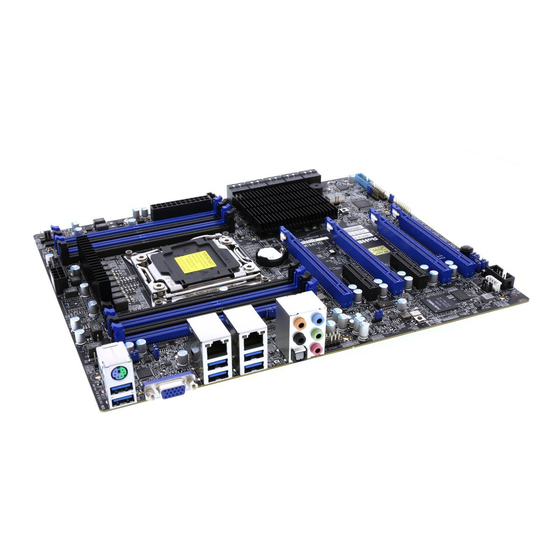
Category: Motherboard
|
Size: 9 MB
Table of Contents
-
Chapter 1
19-
Introduction19
-
Overview19
-
Power Supply24
-
Super I/O24
-
-
Chapter 2
31-
Installation31
-
-
-
Power LED50
-
Hdd Led50
-
NMI Button51
-
Power Fail51
-
Reset Button51
-
Power Button51
-
-
-
C (Jpi2C1)56
-
-
-
C1/I 2 C2)59
-
-
-
Chapter 3
67 -
-
Introduction73
-
-
Motherboard78
-
System Date78
-
System Time78
-
-
-
-
Information79
-
Performance80
-
Enable SMX81
-
PPIN Control81
-
X2Apic81
-
Aes-Ni81
-
Eist82
-
Turbo Mode82
-
-
Chipset84
-
Memory88
-
Event Logs90
-
Management92
-
Ipmi100
-
System Event Log100
-
SEL Components100
-
Erasing Settings101
-
Erase SEL101
-
When SEL Is Full101
-
-
Input/Output103
-
Sata103
-
SATA Controller103
-
-
Ssata105
-
Ssata Controller106
-
-
Pcie/Pci/Pnp108
-
SR-IOV Support108
-
ASPM Support110
-
VGA Priority110
-
USB Settings111
-
XHCI Hand-Off111
-
EHCI Hand-Off111
-
XHCI Mode112
-
Ehci1112
-
Ehci2112
-
Security113
-
Password113
-
User Password114
-
Secure Boot114
-
Secure Boot Mode115
-
-
Key Management115
-
Platform Key115
-
Delete PK115
-
Set New PK115
-
Key Exchange Key116
-
Delete KEK116
-
Set New KEK116
-
Append KEK116
-
Delete DBT116
-
Set New DBT116
-
Append DBT117
-
Delete DBX117
-
Set New DBX117
-
Append DBX117
-
-
Booting118
-
BIOS Features120
-
Retry Boot121
-
CSM Support121
-
EUP Support122
-
Fast Boot122
-
-
Appendix A
123 -
Appendix B
125 -
Appendix C
129 -
Appendix D
133
Advertisement

Supero X10SRA User Manual (143 pages)
Brand: Supero
|
Category: Motherboard
|
Size: 14 MB
Table of Contents
-
-
Overview19
-
Power Supply24
-
Super I/O24
-
-
-
-
Precautions32
-
Unpacking32
-
-
-
-
Power LED49
-
Hdd Led49
-
NMI Button50
-
Power Fail50
-
Reset Button50
-
Power Button50
-
-
-
C (Jpi2C1)55
-
-
-
-
Introduction73
-
Setup Home75
-
-
Motherboard78
-
System Date78
-
System Time78
-
-
Cpu79
-
Memory80
-
Pch81
-
-
-
Information82
-
Performance83
-
PPIN Control83
-
X2Apic84
-
Aes-Ni84
-
-
Eist85
-
Turbo Mode85
-
-
-
Chipset87
-
Memory91
-
-
Temperature93
-
Fan Speed94
-
Voltage95
-
Sata96
-
Ssata98
-
Pcie/Pci/Pnp101
-
NB PCIE Setting101
-
VGA Priority103
-
USB Settings104
-
XHCI Hand-Off104
-
EHCI Hand-Off104
-
XHCI Mode105
-
Ehci1105
-
Ehci2105
-
-
Booting107
-
BIOS Features109
-
Quiet Boot109
-
Retry Boot110
-
CSM Support110
-
EUP Support110
-
Fast Boot110
-
-
User Password111
-
Secure Boot Menu112
-
Secure Boot112
-
Secure Boot Mode112
-
-
Key Management113
-
Platform Key113
-
Delete PK113
-
Set New PK114
-
Key Exchange Key114
-
Delete KEK114
-
Set New KEK114
-
Append KEK114
-
Delete DBT114
-
Set New DBT114
-
Append DBT115
-
Delete DBX115
-
Set New DBX115
-
Append DBX115
-
-
Management116
-
Ipmi123
-
Network Stack126
-
SMBIOS Event Log129
-
Erasing Settings130
-
Advertisement