Table of Contents
Advertisement
Quick Links
Advertisement
Table of Contents

Related Manuals for Supero X10SBA-V


Summary of Contents for Supero X10SBA-V
- Page 1 X10SBA X10SBA-L X10SBA-V USER’S MANUAL Revision 1.0c...
- Page 2 The information in this user’s manual has been carefully reviewed and is believed to be accurate. The vendor assumes no responsibility for any inaccuracies that may be contained in this document, makes no commitment to update or to keep current the information in this manual, or to notify any person or organization of the updates.
-
Page 3: About This Motherboard
Preface Preface This manual is written for system integrators, PC technicians and knowledgeable PC users. It provides information for the installation and use of the X10SBA/-L/-V motherboard. About This Motherboard X10SBA/-L/-V supports the next-generation Intel ® Celeron J1900 SoC (System on a Chip) 22nm Quad-Core processor in the BGA 1170 format. With a 64-bit, 22nm, low-power Tri-gate Quad Core Silvermont processor built into it, the X10SBA(-L) motherboard offers unprecedented enhancements in system performance, power efficiency, and visual/media capability. -
Page 4: Conventions Used In The Manual
X10SBA/-L/-V User’s Manual Conventions Used in the Manual: Special attention should be given to the following symbols for proper installation and to prevent damage done to the components or injury to yourself: Warning: Critical information to prevent damage to the components or injury to your- self. -
Page 5: Contacting Supermicro
Contacting Supermicro Contacting Supermicro Headquarters Address: Super Micro Computer, Inc. 980 Rock Ave. San Jose, CA 95131 U.S.A. Tel: +1 (408) 503-8000 Fax: +1 (408) 503-8008 Email: marketing@supermicro.com (General Information) support@supermicro.com (Technical Support) Website: www.supermicro.com Europe Address: Super Micro Computer B.V. Het Sterrenbeeld 28, 5215 ML 's-Hertogenbosch, The Netherlands Tel:... -
Page 6: Table Of Contents
X10SBA/-L/-V User’s Manual Table of Contents Preface About This Motherboard ....................iii Manual Organization ..................... iii Conventions Used in the Manual: .................iv Contacting Supermicro ....................v Chapter 1 Introduction Overview ......................1-1 Checklist ......................1-1 Motherboard Features ..................1-7 Processor Overview ..................1-10 Special Features ....................1-11 Recovery from AC Power Loss ..............1-11 PC Health Monitoring ..................1-11... - Page 7 Table of Contents Connectors/IO Ports ..................2-10 I/O Back Panel ....................2-10 Universal Serial Bus (USB) ...............2-11 Ethernet Ports ..................2-12 HDMI & DP Ports ..................2-12 Video Connector ..................2-13 Embedded DisplayPort (eDP) ..............2-14 Front Control Panel ..................2-15 Front Control Panel Pin Definitions...............
- Page 8 X10SBA/-L/-V User’s Manual SATA Connections ..................2-31 SATA 2.0 & SATA 3.0 Connections ............2-31 Chapter 3 Troubleshooting Troubleshooting Procedures ................3-1 Before Power On .................... 3-1 No Power ......................3-1 No Video ......................3-2 Memory Errors ....................3-2 Losing the System’s Setup Configuration ............3-2 Technical Support Procedures ................
-
Page 9: Chapter 1 Introduction
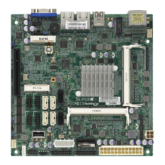
Chapter 1: Introduction Chapter 1 Introduction Overview Checklist Congratulations on purchasing your computer motherboard from an acknowledged leader in the industry. Supermicro boards are designed with the utmost attention to detail to provide you with the highest standards in quality and performance. Please check that the following items have all been included with your motherboard. - Page 10 X10SBA/-L/-V User’s Manual X10SBA/-V Motherboard Image Notes: 1. All graphics shown in this manual were based upon the latest PCB Revision available at the time of publishing of the manual. The motherboard you've received may or may not look exactly the same as the graphics shown in this manual. 2.
- Page 11 Chapter 1: Introduction X10SBA/-L/-V Motherboard Layout USB0(3.0) BIOS AUDIO FP FAN1 HDMI/DP USB1(2.0) JSPDIF_OUT LAN2 LAN1 (for mini-PCI-E only) X10SBA(-L) (for X10SBA/-V only) Rev.1.01A LED3 LED2 (for X10SBA/-V only) (for M-SATA only) BAR CODE JDIMM1 SODIMM2 (1.35V only) (for X10SBA/-V only) (for X10SBA/-V only) JBT1 JSD1...
- Page 12 X10SBA/-L/-V User’s Manual X10SBA/-L/-V Quick Reference USB0(3.0) BIOS AUDIO FP FAN1 HDMI/DP USB1(2.0) JSPDIF_OUT LAN2 LAN1 (for mini-PCI-E only) X10SBA(-L) (for X10SBA/-V only) Rev.1.01A LED3 LED2 (for X10SBA/-V only) (for M-SATA only) BAR CODE JDIMM1 SODIMM2 (1.35V only) (for X10SBA/-V only) (for X10SBA/-V only) JBT1 JSD1...
- Page 13 Chapter 1: Introduction X10SBA/-L/-V Jumpers Jumper Description Default JBT1 CMOS Clear Open: Normal (See Chpt. 2) JPAC1 Audio Enable Pins 1-2 (Enabled) JPME2 Intel Manufacturer Mode Select Pins 1-2 (Normal) JPUSB1 USB Wake Up Enable Pins 1-2 (Enabled) X10SBA/-L/-V Headers/Connectors Connector Description Audio FP...
- Page 14 X10SBA/-L/-V User’s Manual SMBUS1 (JSMB1) 4-Pin External System Management Bus I C Header (JSMB1) Internal Speaker/Buzzer USB 0 Back panel USB 3.0 Port 1 USB 1 Back panel USB 2.0 Port 2 USB 2/3 Front Accessible USB 2.0 Connections: USB 2, USB 3 (USB 3: Only available on the X10SBA-L) USB 4/5 Front Accessible USB 2.0 Connections: USB 4/5 (Only available on...
-
Page 15: Motherboard Features
Chapter 1: Introduction Motherboard Features Single Intel® J1900 SoC (System on a Chip) 64-bit, 22nm Low-Power, Quad-Core processor in the BGA 1170 format Memory Supports up to 8 GB of 204-Pin Unbuffered DDR3L (Low Voltage), Non-ECC, SO-DIMM 1.35V modules of up to 1333 MHz in two horizontal sockets Note: This motherboard supports 1.35V memory only. - Page 16 X10SBA/-L/-V User’s Manual One (1) mini-PCI-Express socket (J1) One (1) mSATA socket (J2) (J2 is not available on the L-Model; J2 support is available only when I-SATA1 is not in use) Video One (1) High Definition Multimedia Interface (HDMI) , One (1) DisplayPort, and One (1) VGA on the back panel One (1) eDP connector (not available on the L model) Audio...
- Page 17 Chapter 1: Introduction Block Diagram System Block Diagram Note: This is a general block diagram and may not exactly represent the features on your motherboard. See the Motherboard Features pages for the actual specifications of each motherboard.
-
Page 18: Processor Overview
X10SBA/-L/-V User’s Manual Processor Overview The X10SBA/-L/-V motherboard supports the next-generation Intel® Celeron J1900 SoC (System on a Chip) 64-bit Quad-Core processor in the BGA 1170 format. Built upon the functionality and capability of the J1900 SoC processor in Low-Power 22nm Microarchitecture, the motherboard offers unprecedented enhancements in system performance, power efficiency, and visual/media capability for SMB entry- level storage, Digital Security, and Digital Signage platforms that are optimized for... -
Page 19: Special Features
Chapter 1: Introduction Special Features Recovery from AC Power Loss Basic I/O System (BIOS) provides a setting for you to determine how the system will respond when AC power is lost and then restored to the system. You can choose for the system to remain powered off, (in which case you must press the power switch to turn it back on), or for it to automatically return to a power-on state. -
Page 20: Acpi Features
X10SBA/-L/-V User’s Manual ACPI Features ACPI stands for Advanced Configuration and Power Interface. The ACPI specifica- tion defines a flexible and abstract hardware interface that provides a standard way to integrate power management features throughout a PC system, including its hardware, operating system and application software. This enables the system to automatically turn on and off peripherals such as CD-ROMs, network cards, hard disk drives and printers. - Page 21 Chapter 1: Introduction as well as an advanced speed with baud rates of 250 K, 500 K, or 1 Mb/s, which support higher speed modems. The Super I/O provides functions that comply with ACPI (Advanced Configuration and Power Interface), which includes support of legacy and ACPI power manage- ment through an SMI or SCI function pin.
- Page 22 X10SBA/-L/-V User’s Manual Notes 1-14...
-
Page 23: Chapter 2 Installation
Chapter 2: Installation Chapter 2 Installation Standardized Warning Statements The following statements are industry-standard warnings, provided to warn the user of situations which have the potential for bodily injury. Should you have questions or experience difficulty, contact Supermicro's Technical Support department for assis- tance. - Page 24 X10SBA/-L/-V User’s Manual Attention Danger d'explosion si la pile n'est pas remplacée correctement. Ne la remplacer que par une pile de type semblable ou équivalent, recommandée par le fabricant. Jeter les piles usagées conformément aux instructions du fabricant. ¡Advertencia! Existe peligro de explosión si la batería se reemplaza de manera incorrecta. Re- emplazar la batería exclusivamente con el mismo tipo o el equivalente recomen- dado por el fabricante.
-
Page 25: Product Disposal
Chapter 2: Installation Product Disposal Warning! Ultimate disposal of this product should be handled according to all national laws and regulations. 製品の廃棄 この製品を廃棄処分する場合、 国の関係する全ての法律 ・ 条例に従い処理する必要が あり ます。 警告 本产品的废弃处理应根据所有国家的法律和规章进行。 警告 本產品的廢棄處理應根據所有國家的法律和規章進行。 Warnung Die Entsorgung dieses Produkts sollte gemäß allen Bestimmungen und Gesetzen des Landes erfolgen. -
Page 26: Static-Sensitive Devices
X10SBA/-L/-V User’s Manual القىانين واللىائح الىطنية جميع وفقا ل ينبغي التعامل معه هذا المنتج من التخلص النهائي عند 경고! 이 제품은 해당 국가의 관련 법규 및 규정에 따라 폐기되어야 합니다. Waarschuwing De uiteindelijke verwijdering van dit product dient te geschieden in overeenstemming met alle nationale wetten en reglementen. -
Page 27: Memory Support
Chapter 2: Installation Memory Support The X10SBA/-L/-V supports up to 8 GB of DDR3L (Low Voltage) Non-ECC SO- DIMM of up to 1333 MHz in two horizontal sockets. This motherboard supports 1.35V memory only. Populate memory on Socket SO-DIMM1 first. Note: Check the Supermicro website for recommended memory modules. -
Page 28: Populating Memory Modules
X10SBA/-L/-V User’s Manual Populating Memory Modules 1. Install the desired number of SO-DIMMs into the memory slots, starting with JDIMM1, then JDIMM2. Pay attention to the notch along the bottom of the module to prevent incorrect DIMM module installation. 2. Insert each SO-DIMM module at the proper angle and snap it into place. Repeat step 1 to install JDIMM2. -
Page 29: Installing A So-Dimm Module Into A Horizontal Socket
Chapter 2: Installation Installing a SO-DIMM Module into a Horizontal Socket 1. Align the receptive point on the bottom of the SO-DIMM module against the key on the memory socket. Note the notches on the side of the SO-DIMM module and those on the socket to avoid causing damage. Receptive Point on SO-DIMM Memory the Module... -
Page 30: Motherboard Installation
X10SBA/-L/-V User’s Manual Motherboard Installation All motherboards have standard mounting holes to fit different types of chassis. Make sure that the locations of all the mounting holes for both motherboard and chassis match. Although a chassis may have both plastic and metal mounting fas- teners, metal ones are highly recommended because they ground the motherboard to the chassis. -
Page 31: Installing The Motherboard
Chapter 2: Installation Installing the Motherboard 1. Install the I/O shield into the back of the chassis. 2. Locate the mounting holes on the motherboard. (See the previous page.) 3. Locate the matching mounting holes on the chassis. Align the mounting holes on the motherboard against the mounting holes on the chassis. -
Page 32: Connectors/Io Ports
X10SBA/-L/-V User’s Manual Connectors/IO Ports The I/O ports are color coded in conformance with the industry standards. See the figure below for the colors and locations of the various I/O ports. I/O Back Panel USB0(3.0) BIOS AUDIO FP FAN1 USB1(2.0) HDMI/DP JSPDIF_OUT LAN2... -
Page 33: Universal Serial Bus (Usb)
Chapter 2: Installation Universal Serial Bus (USB) One Universal Serial Bus 2.0 port (USB 0) and one USB 3.0 port (USB 1) are located on the I/O back panel. Three USB 2.0 connections (USB 2/3, USB 4/5) are located on the motherboard for front USB 2.0 access. In addition, a Type A USB connector (USB 6) is also located on the X10SBA/-V to provide USB 2.0 front support. -
Page 34: Ethernet Ports
X10SBA/-L/-V User’s Manual Ethernet Ports LAN Port Pin Definitions Two Gigabit Ethernet ports (LAN1/ Pin# Definition Pin# Definition LAN2) are located on the I/O back P2V5SB SGND panel to provide network connections. TD0+ Act LED These ports accept RJ45 type cables. TD0- P3V3SB Note: Please refer to the LED... -
Page 35: Video Connector
Chapter 2: Installation Video Connector VGA Pin Pin Definitions A Video (VGA) connector is located Pin# Definition Pin# Definition next to the LAN2 Port on the I/O back Ground panel. This connector is used to pro- Green vide video display. Refer to the board Blue MS1: SDA (DDC layout below for the location. -
Page 36: Embedded Displayport (Edp)
X10SBA/-L/-V User’s Manual Embedded DisplayPort (eDP) Embedded DisplayPort (eDP) Pin Definitions The eDP header is used to connect an Pin# Definition Pin# Definition embedded display LED or LCD Panel. LCD_VCC Lane0_N eDP is a companion standard to the LCD_VCC Lane0_P DisplayPort interface designed for em- LCD_VCC H_GND... -
Page 37: Front Control Panel
Chapter 2: Installation Front Control Panel JF1 contains header pins for various buttons and indicators that are normally located on a control panel at the front of the chassis. These connectors are designed spe- cifically for use with Supermicro chassis. See the figure below for the descriptions of the front control panel buttons and LED indicators. -
Page 38: Front Control Panel Pin Definitions
X10SBA/-L/-V User’s Manual Front Control Panel Pin Definitions Power LED Power LED Pin Definitions (JF1) The Power LED connection is located Pin# Definition on pins 15 and 16 of JF1. Refer to the table on the right for pin definitions. Ground HDD LED HDD LED... -
Page 39: Nic1/Nic2 (Lan1/Lan2)
Chapter 2: Installation NIC1/NIC2 (LAN1/LAN2) LAN1/LAN2 LED Pin Definitions (JF1) The NIC (Network Interface Controller) Pin# Definition LED connection for LAN port 1 is located 9/11 on pins 11 and 12 of JF1, and the LED 10/12 Ground connection for LAN Port 2 is on pins 9 and 10. -
Page 40: Reset Button
X10SBA/-L/-V User’s Manual Reset Button Reset Button The Reset Button connection is located Pin Definitions (JF1) on pins 3 and 4 of JF1. Attach it to a Pin# Definition hardware reset switch on the computer Reset case to reset the system. Refer to the Ground table on the right for pin definitions. -
Page 41: Connecting Cables
Chapter 2: Installation Connecting Cables This section provides brief descriptions and pin-out definitions for onboard headers and connectors. Be sure to use the correct cable for each header or connector. For information on Backpanel USB and Front Panel USB ports, refer to page 2-11. ATX Power 24-pin Connector ATX PWR &... -
Page 42: Dom Pwr Connector (Jsd1)
X10SBA/-L/-V User’s Manual DOM PWR Connector (JSD1) DOM PWR Pin Definitions The SATA Disk-On-Module (DOM) power con- Pin# Definition nector, located at JSD1, provides power to a solid state DOM storage device connected to Ground one of the SATA ports. See the table on the Ground right for pin definitions. -
Page 43: Internal Buzzer (Sp1)
Chapter 2: Installation Internal Buzzer (SP1) Internal Buzzer Pin Definition The Internal Buzzer (SP1) can be Pin# Definitions used to provide audible indications for Pin 1 Pos. (+) Beep In various beep codes. See the tables on Pin 2 Neg. (-) Alarm the right for pin definitions. -
Page 44: Serial Ports (Com1-Com4)
X10SBA/-L/-V User’s Manual Serial Ports (COM1-COM4) Serial/COM Ports Pin Definitions There are two serial (COM) port head- Pin# Definition Pin# Definition ers on the motherboard. Refer to the layout below for COM port locations. See the table on the right for pin definitions. -
Page 45: Tpm Header/Port 80 Header
Chapter 2: Installation TPM Header/Port 80 Header TPM/Port 80 Header Pin Definitions A Trusted Platform Module/Port 80 Pin# Definition Pin# Definition header is located at JTPM1 to provide LCLK TPM support and Port 80 connection. LFRAME# <(KEY)> Use this header to enhance system LRESET# +5V (X) performance and data security. -
Page 46: Smbus1
X10SBA/-L/-V User’s Manual SMBUS1 SMBUS1 Header Pin Definitions A System Management Bus header Pin# Definition for the SMBus slave sensor is located Data at JSMB1. Connect the appropriate Ground cable here to use the SMBus I C con- nection on your system. Clock No Connection Overheat/Fan Fail LED... -
Page 47: Gpio Header (Jp1)
Chapter 2: Installation GPIO Header (JP1) The JP1 header is located near the onboard battery on the motherboard. JP1 is a 10-pin general purpose I/O header. Each pin can be configured to be an input pin or open drain output pin. See the table below for pin definitions. General Purpose I/O Header Pin Definitions Pin#... -
Page 48: Jumper Settings
X10SBA/-L/-V User’s Manual Jumper Settings Explanation of Jumpers To modify the operation of the mother- board, jumpers can be used to choose between optional settings. Jumpers create shorts between two pins to change the function of the connector. Pin 1 is identified with a square solder pad on the printed circuit board. -
Page 49: Cmos Clear
Chapter 2: Installation CMOS Clear JBT1 is used to clear CMOS. Instead of pins, this jumper consists of contact pads to prevent accidental clearing of CMOS. To clear CMOS, use a metal object such as a small screwdriver to touch both pads at the same time to short the connec- tion. -
Page 50: Usb Wake Up
X10SBA/-L/-V User’s Manual USB Wake Up USB Wake Up Enable Jumper Settings Use the jumper JPUSB1 to wake up your Pin# Definition system by pressing a key on a USB keyboard Enabled (Default) or clicking the USB mouse connected to the Disabled onboard USB ports. -
Page 51: Onboard Indicators
Chapter 2: Installation Onboard Indicators LAN1 LAN2 Link LED Activity LED LAN 1/LAN 2 LEDs Two LAN ports (LAN 1/LAN 2) are located GLAN 1/2 Activity Indicator on the I/O back panel of the motherboard. LED Settings Each Ethernet LAN port has two LEDs. The Color Status Definition... -
Page 52: Main Power Led
X10SBA/-L/-V User’s Manual Main Power LED Main PWR LED Indicator LED Settings A Main Power LED is located at LED1 LED Color Definition on the motherboard. When this LED is System Off (PWR cable not connected) on, the system power is on. Be sure to Green System Power On turn off the system power and unplug the... -
Page 53: Sata Connections
Chapter 2: Installation SATA Connections SATA 2.0 & SATA 3.0 Connections SATA 2.0/3.0 Connectors Pin Definitions Two Serial ATA (SATA) 2.0 connectors (I- Pin# Signal SATA 0/1) are located on the motherboard to Ground provide optional power source. In addition, SATA_TXP four SATA 3.0 ports (M-SATA 0-3) are located SATA_TXN... - Page 54 X10SBA/-L/-V User’s Manual Notes 2-32...
-
Page 55: Chapter 3 Troubleshooting
Chapter 3: Troubleshooting Chapter 3 Troubleshooting Troubleshooting Procedures Use the following procedures to troubleshoot your system. If you have followed all of the procedures below and still need assistance, refer to the ‘Technical Support Procedures’ and/or ‘Returning Merchandise for Service’ section(s) in this chapter. Always disconnect the AC power cord before adding, changing or installing any hardware components. -
Page 56: No Video
X10SBA/-L/-V User’s Manual No Video 1. If the power is on, but you have no video--in this case, you will need to re- move all the add-on cards and cables first. 2. Use the speaker to determine if any beep codes exist. (Refer to Appendix A for details on beep codes.) 3. -
Page 57: Technical Support Procedures
Chapter 3: Troubleshooting Technical Support Procedures Before contacting Technical Support, please make sure that you have followed all the steps listed below. Also, Note that as a motherboard manufacturer, Supermicro does not sell directly to end users, so it is best to first check with your distributor or reseller for troubleshooting services. -
Page 58: Frequently Asked Questions
X10SBA/-L/-V User’s Manual Frequently Asked Questions Question: What type of memory does my motherboard support? Answer: The X10SBA/-L/-V supports unbuffered Non-ECC DDR3L Low Voltage SO-DIMM (1.35V, of up to 1333 MHz). See Section 2-4 for details on installing memory. Question: How do I update my BIOS? Answer: We do NOT recommend that you upgrade your BIOS if you are not experiencing any problems with your system. -
Page 59: Battery Removal And Installation
Chapter 3: Troubleshooting Important: The SPI BIOS chip installed on this motherboard is not re- movable. To repair or replace a damaged BIOS chip, please send your motherboard to RMA at Supermicro for service. Question: I think my BIOS is corrupted. How can I recover my BIOS? Answer: Please see Appendix C-BIOS Recovery for detailed instructions. -
Page 60: Returning Merchandise For Service
X10SBA/-L/-V User’s Manual Battery Installation 1. To install an onboard battery, follow the steps 1 and 2 above and continue below: 2. Identify the battery's polarity. The positive (+) side should be facing up. 3. Insert the battery into the battery holder and push it down until you hear a click to ensure that the battery is securely locked. -
Page 61: Chapter 4 Uefi Bios
Chapter 4: AMI BIOS Chapter 4 UEFI BIOS Introduction This chapter describes the AMI BIOS setup utility for the X10SBA (-F). The ROM BIOS is stored in a Flash EEPROM and can be easily updated. This chapter de- scribes the basic navigation of the AMI BIOS setup utility screens. Note: For AMI BIOS recovery, please refer to the UEFI BIOS Recovery Instructions in Appendix C. -
Page 62: Main Setup
X10SBA/-L/-V User’s Manual How to Start the Setup Utility Normally, the only visible Power-On Self-Test (POST) routine is the memory test. As the memory is being tested, press the <Delete> key to enter the main menu of the AMI BIOS setup utility. From the main menu, you can access the other setup screens. - Page 63 Chapter 4: AMI BIOS System Date/System Time Use this option to change the system date and time. Highlight System Date or System Time using the arrow keys. Enter new values using the keyboard. Press the <Tab> key or the arrow keys to move between fields. The date must be entered in MM/DD/YYYY format.
-
Page 64: Advanced Setup Configurations
X10SBA/-L/-V User’s Manual Advanced Setup Configurations Use the arrow keys to select Advanced Setup and press <Enter> to access the submenu items: Aptio Setup Utility - Copyright (C) 2013 American Megatrends, Inc. Main Advanced Boot Security Save & Exit System Boot Feature Setting ... - Page 65 Chapter 4: AMI BIOS Wait For 'F1' If Error This feature forces the system to wait until the 'F1' key is pressed if an error oc- curs. The options are Disabled and Enabled. Interrupt 19 Capture Interrupt 19 is the software interrupt that handles the boot disk function. When this item is set to Enabled, the ROM BIOS of the host adaptors will "capture"...
- Page 66 X10SBA/-L/-V User’s Manual Chipset Configuration Warning: Setting the wrong values in the following sections may cause the system to malfunction. North Bridge The following North Bridge information will be displayed: Graphics Configuration This item displays the following graphics information: GOP Configuration GOP Driver Select Enabled to enable GOP driver and to load the VBIOS.
- Page 67 Chapter 4: AMI BIOS DVMT Total Gfx Mem Use this feature to set the total memory size to be used by the internal graph- ics devices based on the DVMT 5.0 platform. The options are 128MB, 256MB and MAX. Aperture Size Use this feature to set the Aperture size, which is the size of system memory reserved by the BIOS for graphics device use.
- Page 68 X10SBA/-L/-V User’s Manual Azalia HDMI Codec Select Enabled to enable the internal HDMI CODEC (Coder-Decoder) for Azalia. The settings are Enabled and Disabled. USB Configuration Legacy USB Support This feature enables support for legacy USB devices. Select Auto to disable legacy support if USB devices are not present.
- Page 69 Chapter 4: AMI BIOS USB Port 2 Select Enabled for USB Port 2 support. The options are Enabled and Disabled. USB Port 3 Select Enabled for USB Port 3 support. The options are Enabled and Disabled. PCI Express Configuration This item displays the information of onboard PCI-E slots.
- Page 70 X10SBA/-L/-V User’s Manual pendency on other timestamp calculation devices, such as an x86 RDTSC Instruc- tion embedded in the CPU. The High Performance Event Timer is used to replace the 8254 Programmable Interval Timer. The options are Enabled and Disabled. Boot Timer with HPET Timer (High Precision Event Timer) Select Enabled to allow the Boot Timer to take the input from the High Precision Time into calculation when calculating time events for the system.
- Page 71 Chapter 4: AMI BIOS Hardware Health Configuration PC Health Status Fan Speed Control Mode This feature allows the user to decide how the system controls the speeds of the onboard fans. The CPU temperature and the fan speed are correlative. When the CPU on-die temperature increases, the fan speed will also increase for effective system cooling.
- Page 72 X10SBA/-L/-V User’s Manual Serial Port Console Redirection COM0 Use this feature to enable console redirection for the COM0 port. The options are Enabled and Disabled. Console Redirection Settings This feature allows the user to specify how the host computer will exchange data with the client computer, which is the remote computer used by the user.
- Page 73 Chapter 4: AMI BIOS Flow Control This feature allows the user to set the flow control for Console Redirection to prevent data loss caused by buffer overflow. Send a "Stop" signal to stop send- ing data when the receiving buffer is full. Send a "Start" signal to start sending data when the receiving buffer is empty.
- Page 74 X10SBA/-L/-V User’s Manual Console Redirection Settings (for EMS) This feature allows the user to specify how the host computer will exchange data with the client computer, which is the remote computer used by the user. Out-of-Band Management Port The feature selects a serial port used by the Microsoft Windows Emergency Management Services (EMS) to communicate with a remote server.
- Page 75 Chapter 4: AMI BIOS CPU Configuration Socket 0 CPU Configuration The following CPU information will be displayed: • Type of CPU • CPU Signature • Microcode Patch • Max (Maximum) CPU Speed • Min (Minimum) CPU Speed • Processor Cores •...
- Page 76 X10SBA/-L/-V User’s Manual cannot, thus preventing a worm or a virus from flooding illegal codes to overwhelm the processor or damage the system during an attack. The default is Enabled. (Refer to Intel and Microsoft Web Sites for more information.) Hardware Prefetcher (Available when supported by the CPU) If set to Enabled, the hardware prefetcher will prefetch streams of data and instruc- tions from the main memory to the L2 cache to improve CPU performance.
- Page 77 Chapter 4: AMI BIOS SATA Mode (Available when the item: Serial-ATA is enabled) This item selects the mode for the installed SATA drives. The options are IDE Mode, and AHCI Mode. If the item above -SATA Mode Select is set to AHCI, the following items are dis- played: Serial-ATA Port 0/ Serial-ATA Port 1 Select Enabled to enable a SATA port specified by the user.
- Page 78 X10SBA/-L/-V User’s Manual PCIe/PCI/PnP Configuration This feature allows the user to set the PCI/PnP configurations for the following items: VGA Palette Snoop Select Enabled to support VGA palette register snooping which will allow the PCI cards that do not contain their own VGA color palette to examine the video cards palette and mimic it for proper color display.
- Page 79 Chapter 4: AMI BIOS Slot1 PCI-E 2.0 x2 (in x8) OPROM Use this feature to enable or disable PCI-Express slot Option ROM support to boot the computer using a device installed on the slot specified by the user. The options are Disabled, Legacy, EFI, and EFI and Legacy.
- Page 80 X10SBA/-L/-V User’s Manual iSCSi Configuration iSCSI Initiator Name This feature allows the user to enter the unique name of the iSCSI Initiator in IQN format. Once the name of the iSCSI Initiator is entered into the system, configure the proper settings for the following items. Add an Attempt ...
- Page 81 Chapter 4: AMI BIOS Link Status MAC Address: Virtual MAC Address: 4-21...
-
Page 82: Security Settings
X10SBA/-L/-V User’s Manual Security Settings This menu allows the user to configure the following security settings for the system. Aptio Setup Utility - Copyright (C) 2013 American Megatrends, Inc. Main Advanced Security Boot Exit Password Description Set Administrator Password. If ONLY the administrator’s password is set, then this only limits access to Setup and is only asked for when entering Setup. - Page 83 Chapter 4: AMI BIOS Key Management Default Keys Provision Select Enable to install all manufacture defaults for the following system security settings. The options are Disabled and Enabled. Delete All Secure Boot Variables This feature allows the user to delete all secure boot settings previous stored in the system.
- Page 84 X10SBA/-L/-V User’s Manual Authorized Signatures Delete DB (DataBase) Select <Yes> to confirm deletion of a database from the NVRAM (Non-Volatile RAM). Set New DB (DataBase) Select <Yes> to confirm that a new database will be set in the NVRAM (Non-Volatile RAM).
-
Page 85: Boot Settings
Chapter 4: AMI BIOS Boot Settings Use this feature to configure Boot Settings: Aptio Setup Utility - Copyright (C) 2013 American Megatrends, Inc. Main Advanced Security Boot Exit Boot Priority Sets the system boot order Boot Order #1 [UEFI Hard Disk] Boot Order #2 [UEFI CD/DVD] Boot Order #3... - Page 86 X10SBA/-L/-V User’s Manual Hard Disk Drive BBS Priorities • Boot Order #1 CDROM/DVD Drive BBS Priorities • Boot Order #1 Network Drive BBS Priorities • Boot Order #1 USB Key Drive BBS Priorities • Boot Order #1 ...
-
Page 87: Save & Exit
Chapter 4: AMI BIOS Save & Exit Select the Exit tab from the BIOS setup utility screen to enter the Exit BIOS Setup screen. Aptio Setup Utility - Copyright (C) 2013 American Megatrends, Inc. Main Advanced Security Boot Save & Exit Exit system setup after saving the Discard Changes and Exit changes. - Page 88 X10SBA/-L/-V User’s Manual Save As User Defaults To set this feature, select Save as User Defaults from the Exit menu and press <En- ter>. This enables the user to save any changes to the BIOS setup for future use. Restore User Defaults To set this feature, select Restore User Defaults from the Exit menu and press <En- ter>.
-
Page 89: Appendix A Bios Error Beep Codes
Appendix A: POST Error Beep Codes Appendix A BIOS Error Beep Codes During the POST (Power-On Self-Test) routines, which are performed each time the system is powered on, errors may occur. Non-fatal errors are those which, in most cases, allow the system to continue with bootup. - Page 90 X10SBA/-L/-V User’s Manual Notes...
-
Page 91: Appendix B Software Installation Instructions
Appendix B: Software Installation Instructions Appendix B Software Installation Instructions B-1 Installing Drivers After you've installed the Windows Operating System, a screen as shown below will appear. You are ready to install software programs and drivers that have not yet been installed. -
Page 92: Configuring Superdoctor 5
X10SBA/-L/-V User’s Manual B-2 Configuring SuperDoctor 5 The Supermicro SuperDoctor® 5 is a program that functions in a command-line or web-based interface in Windows and Linux operating systems. The program moni- tors system health information such as CPU temperature, system voltages, system power consumption, fan speed, and provides alerts via email or Simple Network Management Protocol (SNMP). -
Page 93: Appendix C Uefi Bios Recovery Instructions
Appendix C: UEFI BIOS Recovery Appendix C UEFI BIOS Recovery Instructions Warning: Do not upgrade the BIOS unless your system has a BIOS-related issue. Flashing the wrong BIOS can cause irreparable damage to the system. In no event shall Supermicro be liable for direct, indirect, special, incidental, or consequential damages arising from a BIOS update. - Page 94 X10SBA/-L/-V User’s Manual To perform UEFI BIOS recovery using a USB-attached device, follow the instruc- tions below. 1. Using a different machine, copy the "Super.ROM" binary image file into the disc Root "\" Directory of a USB device or a writeable CD/DVD. Note: If you cannot locate the "Super.ROM"...
- Page 95 Appendix C: UEFI BIOS Recovery 6. After the process of BIOS Recovery is complete, press any key to reboot the system. 7. Using a different system, extract the BIOS package into a bootable USB flash drive. 8. When a DOS prompt appears, enter AMI.BAT BIOSname.### at the prompt. Note: Do not interrupt this process until BIOS flashing is completed.
- Page 96 X10SBA/-L/-V User’s Manual 9. After seeing the message that BIOS update is completed, unplug the AC pow- er cable from the power supply to clear CMOS, and then plug the AC power cable in the power supply again to power on the system. 10.
-
Page 97: Appendix D Dual Boot Block
Appendix D: Dual Boot Block Appendix D Dual Boot Block D-1 Introduction This motherboard supports the Dual Boot Block feature, which is the last-ditch mechanism to recover the BIOS boot block. This section provides an introduction to the feature. BIOS Boot Block A BIOS boot block is the minimum BIOS loader required to enable necessary hardware components for the BIOS crisis recovery flash that will update the main BIOS block. -
Page 98: Steps To Reboot The System By Using Jumper Jbr1
X10SBA/-L/-V User’s Manual D-2 Steps to Reboot the System by Using Jumper JBR1 1. Power down the system. 2. Close pins 2-3 on Jumper JBR1, and power on the system. 3. Follow the BIOS recovery SOP listed in the previous chapter (Appendix C). 4. - Page 99 (Disclaimer Continued) The products sold by Supermicro are not intended for and will not be used in life support systems, medical equipment, nuclear facilities or systems, aircraft, aircraft devices, aircraft/emergency com- munication devices or other critical systems whose failure to perform be reasonably expected to result in significant injury or loss of life or catastrophic property damage.
Need help?
Do you have a question about the X10SBA-V and is the answer not in the manual?
Questions and answers