Table of Contents
Advertisement
Quick Links
Download this manual
See also:
User Manual
Advertisement
Table of Contents

Related Manuals for ACTi ACD-2200


Summary of Contents for ACTi ACD-2200
-
Page 1: Quick Installation Guide
4 CH Video Server ACD-2200 Quick Installation Guide Ver.070831... -
Page 2: Getting Started
Getting Started PACKAGE CONTENTS ACD-2200 Warranty Card Software CD Terminal Blocks & Screws Power Adaptor (Option) -
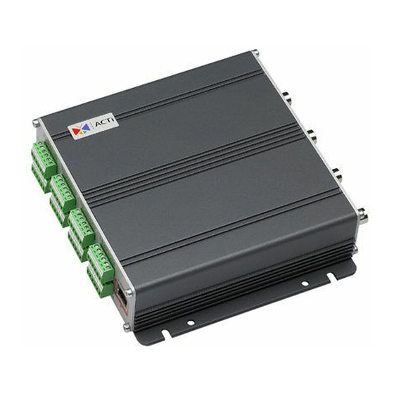
Page 3: Physical Description
1.2 PHYSICAL DESCRIPTION Channel Number Video Input Each channel supports one analog video input of composite signal with BNC connectors. Audio Input / Output The video server supports one audio input and output with earphone jack. ETHERNET Port The Video server connects to the Ethernet via a standard RJ45 connector. Supporting NWAY, this Video server can auto detect the speed of local network segment (10Base-T/100Base-TX Ethernet). - Page 4 Step 1: Switch off video server by disconnecting the power cable Step 2: Using a suitable pointed object, press and continue to hold the Reset Button depressed. While continuing to hold the reset button depressed, reconnect the power cable. Step 3: Keep holding the reset button depressed around 6 seconds, release the reset button.
- Page 5 DESCRIPTION NAME RS-485 RS-422 RS-232* Power Input (DC +12V) Ground Pin of Power Input & RS-232 * RS-232 mode requires user to set the jumpers inside the video server. Bcause opening the video server will void the warranty, please contact your distributor for how to switch to RS-232 mode.
-
Page 6: Quick Tour
Quick Tour This section guides you with a quick tour on video server. 2.1 Configure the Video Server 2.1.1 Make sure network environment Default IP of video server is 192.168.0.100. Please make sure video server and your PC are on the same network segment before running the installation. Please set the settings as below. - Page 7 2.1.2 Open Internet Explorer with IP address STEP1: Open a browser STEP2: Enter the IP address of the IP device. The default IP address is “192.168.0.100” The “Login Page” is now displayed as below. STEP3: Enter the Account name (factory default: Admin) and the Password (factory default: 123456).
- Page 8 STEP1: Click to set system configurations of 4-CH Video Server STEP2: Click to apply the choice...
- Page 9 2.1.3 Set New IP Click the [WAN Setting] on the “Main Setup page”. The “WAN setting page” is displayed as below. *IP Address : The IP address of the LAN interface. The default IP address is 192.168.0.100. *Subnet Mask : The subnet mask of the LAN interface.The default subnet mask is 255.255.255.0 *Click button...
- Page 10 NOTE: Check with your MIS department, if Client PC and IP rugged dome are setting in different VLANs, please connect to WAN port. NOTE: In your Client PC, please make sure the setting of Network Connections Type is set to Auto Negotation, since IP rugged dome follows MII standard.
- Page 11 2.1.4 Save Reboot STEP1: Click the [Save and reboot] on the “Main Setup page”. The “Save and reboot page” is displayed as below. STEP2: The Action LED indicator will light down to indicate that the IP device is rebooting. After around 30 seconds, the Action LED will light up again to indicate that the reboot is completed.
- Page 12 2.1.5 Configuring the IP device – Channel This section describes how to configure the system part of IP device. STEP1: Click to set configurations of every single channel of 4-CH Video Server STEP2: Click to apply the choice...
- Page 13 2.1.6 Preview the video STEP1: Click the [Video Display] on the “Main Setup page”. The “Video Display page” is displayed as below. STEP2: Check the [Mute] checkbox to select mute enable/disable STEP3: Click the [Audio Out] checkbox to enable/disable audio output from control PC to IP device.
- Page 14 2.1.7 Check Default Video Setting STEP1: Click the [Video Setting] on the “Main Setup page”. The “Video setting page” is displayed as below. STEP2: Clieck to enter the configuration table...
- Page 15 Click the [Apply] button of each setting to confirm the settings or click the [Reset] button to re-enter the parameters. NOTE: Please make sure the TV Input (NTSC / PAL) is meet your requirement, and click button.
Need help?
Do you have a question about the ACD-2200 and is the answer not in the manual?
Questions and answers