Table of Contents
Advertisement
Quick Links
Advertisement
Table of Contents

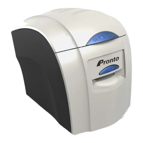
Summary of Contents for Pronto MAGICARD 3649 - 0001
- Page 1 Colour ID Card Printer MAGICARD Pronto Maintenance Manual Issue 1 22/01/09 Magicard Pronto single sided colour ID Card Printer - 3649 - 0001 Magicard Pronto Mag single sided colour ID Card Printer - 3649 - 0002 Standard Standard Standard Option...
-
Page 2: Table Of Contents
..................................- 8 - section 1.2 badge design ..................................... - 8 - SECTION 2 KEY FEATURES OF THE MAGICARD PRONTO..................- 9 - section 2.1 specification of the magicard PRONTO............................- 10 - SECTION 3 COMPONENT LAYOUT ..........................- 11 - SECTION 4 DYE FILM OPTIONS .......................... - Page 3 SECTION 14.2 Basic Magnetic Encoding................................- 60 - SECTION 14.3 Encoding using Badge printing Software............................- 61 - section 14.4 ASCII Character Set supported by the PRONTO ..........................- 62 - section 14.5 ISO standards....................................- 62 - section 14.6 error checking.
-
Page 4: Conventions
The Ultra Secure feature of Magicard® Printers is protected by US PATENT No: 5,990,918 and by EUROPEAN PATENT SPECIFICATION EP 0 817 726 B1. Microsoft and Windows 2000, XP and Vista are trademarks of Microsoft Corporation. Copyright © 2004 Ultra Electronics Limited. Pronto Maintenance Manual - 4 -... -
Page 5: Safety Instructions
The correct Power Supply provided by Magicard. Ambient temperature +10 to +30 degrees Centigrade. Relative Humidity 20/70% RH. Protection from direct sunlight and chemicals. Protection from abrupt temperature changes. Pronto Maintenance Manual - 5 -... -
Page 6: Introduction To The Printing Process
Since longevity is something we all want from our prints, it’s also reassuring to know that because dyes sublimate instead of just being painted onto it’s surface, dye sublimation prints resist fading and are colourfast. Pronto Maintenance Manual - 6 -... - Page 7 Card. All monitors will show the same image slightly differently. Different plastic surfaces will give differing results and the Dye-Film could vary slightly from batch to batch. For these reasons, the Printer Driver has been designed to allow the user to adjust various aspects of the colour output. Pronto Maintenance Manual - 7 -...
-
Page 8: Card Design Limitations
It is more important to ensure the colour of any picture element is correct when printed (even if the colour looks incorrect on the screen). Pronto Maintenance Manual - 8 -... -
Page 9: Section 2 Key Features Of The Magicard Pronto
Attractive, compact design. Multicoloured front Panel Button giving a clear indication of status. USB interface. Microsoft Certified “Plug and Play” Driver make the Pronto easy to install and use. Secure Magicard Pronto features the patented “Holokote” watermark technology. Holokote watermark is printed on the Card during the normal print cycle at no extra cost. -
Page 10: Specification Of The Magicard Pronto
Ultra Electronics Ltd SECTION 2.1 SPECIFICATION OF THE MAGICARD PRONTO Printing Method : Direct to Card Dye Sublimation. Feed Format : Hand Feed. Resolution : 300 dots per inch (11.8 Dots per mm). Colour Reproduction : 256 graduations for each colour. -
Page 11: Section 3 Component Layout
Ultra Electronics Ltd SECTION 3 COMPONENT LAYOUT Top Cover Opening Latch Print Head Assembly Multicoloured Button Hand Feed Entry / Exit Slot Printer Connections USB Socket DC Power Input Pronto Maintenance Manual - 11 -... - Page 12 Used Dye Film Spool Holder Cleaning Roller Cassette Top Cover Opening Catch Top Cover Holding Latches Print Head Cooling Fan Print Head Assembly Dye Film Sensor Bracket (upper) Card Hand Feed Entry / Exit Slot Pronto Maintenance Manual - 12 -...
- Page 13 Magnetic Encoder Roller Top Cover Interlock Sensor Dye Film Sensor Bracket (lower) Dye Film Drive Gear Rear Card Opto Sensor Print Head Roller Mid Card Opto Sensor Front Pinch Roller Front Card Opto Sensor Pronto Maintenance Manual - 13 -...
-
Page 14: Section 4 Dye Film Options
SECTION 4 DYE FILM OPTIONS MA300YMCKO Dye-Film is the appropriate choice for colour printing with the Pronto. MA1000K & MA600KO Dye-Film – where cost is critical, monochrome printing is a fraction of the cost of colour printing. The Table below is a guide to selecting the best Dye-Film to use for any intended application. -
Page 15: Loading The Dye Film
Gently close the top cover until it clicks into the closed position. The Printer will automatically recognise the type of Film that has been loaded by reading the RFID Tag when it initialises. Pronto Maintenance Manual - 15 -... -
Page 16: Cards
Free from pits or bumps in the surface. Printable Area of the Card The Pronto Printer offers high quality edge to edge (full bleed) printing. Thus the surface of the Card may be printed “edge to edge”. Die cut PVC Cards typically have an edge roll off (bevel) which can result in a fine white line around the edge of full bleed printed Cards. - Page 17 “Smart Cards” must conform to the ISO 7816 specification, with the chip contacts being below the surface of the Card. It is unwise to print graphics or text directly adjacent to the chip as image quality may be affected. Pronto Maintenance Manual - 17 -...
-
Page 18: Section 5 Philosophy
Field Repair Every precaution has been taken in the design of the Pronto Printer to ensure user problems are rare. We have also tried to anticipate any possible problems in the field, due to misuse, accidental failure or component failure. This Manual should enable the Service Agent to identify any module or component that has failed, replace it, and carry out the appropriate setting up and testing to ensure satisfactory operation. -
Page 19: Section 6 Warranty Information
Please also mark the MRAN number on the outside of the shipping carton. All Customs Duties and Taxes, if applicable, are the responsibility of the Customer. Pronto Maintenance Manual - 19 -... -
Page 20: Internet Support
INTERNET SUPPORT To further enhance the Customer Support already available to Magicard Customers, the Magicard Web site contains useful information on both problem solving and operation of the Pronto Printer. The web-site is available 24 hours per day at www.magicard.com SECTION 6.3... -
Page 21: Section 7 Cleaning The Printer
Follow the instructions on page 22 for cleaning the Printer. SECTION 7.2 CLEANING SUPPLIES Three Cleaning Cards and a cleaning Roller are included with each new Pronto Printer. You can purchase additional Cleaning Kits, which includeCleaning Cards, Rollers and Pens. Cleaning Kits Part Number CK1 (10 Cleaning Cards, 5 Rollers and a Cleaning Pen). -
Page 22: Cleaning The Printer Rollers
The Card will automatically enter the Printer and the Rollers will be cleaned. When the cleaning cycle is finished, the Cleaning Card will be ejected. Turn the Cleaning Card over and repeat steps 2 – 4. 5. Close all Driver windows. Pronto Maintenance Manual - 22 -... -
Page 23: Replacing The Cleaning Roller
3. Slide the central Roller Bar through the middle of the new “Sticky” Roller. Refit Roller to Cassette. 4. Carefully remove the protective paper layer to reveal the sticky surface. 5. Refit the Cleaning Cassette into the Printer. Central Roller Cleaning Cassette Pronto Maintenance Manual - 23 -... -
Page 24: Cleaning The Print Head
1. Use the special Print Head cleaning Pen from your Magicard Printer Cleaning Kit. See Section 6.1 ‘Cleaning Supplies’. 2. Open the Printer and draw the Pen several times across the complete length of the Print Head. Cleaning the Printer’s Print Head with a Cleaning pen Pronto Maintenance Manual - 24 -... -
Page 25: Section 8 Magicard Pronto Driver
Ultra Electronics Ltd SECTION 8 MAGICARD PRONTO DRIVER. Pronto and Pronto Mag use the new “UltraDriver”. This Driver is for use on the following Operating Systems only : Windows 2000 & Windows XP (32 bit only). Windows 2003 Server (32 bit only). - Page 26 Recover the file as follows :- Navigate to c:\windows\inf (Windows XP) or c:\winnt\inf (Windows 2000). Find the file named “usbprint.in”, and then rename it to < usbprint.inf. > Reconnect the USB cable. Pronto Maintenance Manual - 26 -...
-
Page 27: Un-Installing The Driver For Windows 2000 / Xp / 2003 Server
Select the “Magicard Printer entry, and click on “Change/Remove” Choose the “Magicard Printer you wish to remove (there may be more than one), and click “Next” Lastly - simply follow the on-screen prompts ! Pronto Maintenance Manual - 27 -... -
Page 28: Un-Installing The Driver For Windows Vista
Category View choose followed by “Control Panel” “Uninstall a Program…” Category view Classic View choose “Program and Features…” Select the Magicard Printer and the choose the “Uninstall / Change” Button Follow the instructions on the screen Pronto Maintenance Manual - 28 -... -
Page 29: Driver Description
Driver setting. To view the Driver’s help file, go to the Printer Preferences (as described above), and click on the “Help” Button in any of the Tabs. Pronto Maintenance Manual - 29 -... -
Page 30: Section 9 Printer Functions
PRINTING A TEST CARD The Pronto is able to print an internal Test Card independently of it’s Host Computer. This function is useful test to check the Printer is working correctly without involving any Computer software or Printer Driver settings. -
Page 31: Soak Test Mode
The Soak Test Mode moves every mechanical part of the machine, including the Print Head cooling Fan. A blank Card will be needed (inserted from the front). There are two Soak Test Modes available on the Pronto (one with, and one without the Dye-Film fitted). No Dye-Film fitted ... -
Page 32: Section 10 Print Head Replacement
Ultra Electronics Ltd SECTION 10 PRINT HEAD REPLACEMENT This section describes the action needed to replace the Print Head in the Pronto Printer. SECTION 10.1 PRINT HEAD DAMAGE. Dust or contamination on the Card or Dye-Film is dragged below the Print Head. This causes scratches which permanently damage the printing surface. -
Page 33: Print Head Electronic Failure
The following procedures involve contact with Electrostatic Sensitive Devices. All precautions for handling Electrostatic Sensitive Devices should be followed at all times (including the use of a grounded wrist strap). HOLD ! Switch the Printer Off ! Pronto Maintenance Manual - 33 -... -
Page 34: Replacing The Print Head (Cont)
Care must be taken when disconnecting and connecting the Print Head Assembly. The electrical connector (located on the Print Head) is mounted on a soft flexible electronic circuit board. Damage can occur if excessive force is used at any time. Pronto Maintenance Manual - 34 -... -
Page 35: Setting The Print Head Density Calibration
Print Heads and therefore should only be used for a specific Print Head assembly. Whilst the Printer Lid is open … Print Head Density Programmer (PDP) Close the Printer Lid DONE ! Pronto Maintenance Manual - 35 -... -
Page 36: Print Head Setup And Adjustment
Dye-Film overheating. Rear of the Card is variation across the Card. the Card. Front of the Card is the end that the end that ejects out of the Printer last. ejects out of the Printer first. Pronto Maintenance Manual - 36 -... -
Page 37: Section 11 Dismantling And Assembling The Printer
DISMANTLING AND ASSEMBLING THE PRINTER The Magicard Pronto Printer has been designed with a modular construction to make servicing and repair very easy. The following guidelines show you how to change the middle Card Sensor which is the most difficult component to replace. -
Page 38: Removal & Refitting Of The Top Dye-Film Sensor
Turn the plastic cross piece over and disconnect the Sensor cable from the small PCB. The Sensor PCB can now be unclipped from the plastic cross piece. Refitting is the reverse procedure ensuring the plastic cross piece is located into the side plates. Pronto Maintenance Manual - 38 -... -
Page 39: Removing & Refitting The Controller Pcb
Disconnect all the wiring from around the outside edge of the Controller PCB. Unclip the four plastic catches and remove the Controller PCB downwards. On Pronto Printers with the Magnetic Encoding option, an extra PCB will need to be disconnected, it is mounted onto the main Controller PCB. -
Page 40: Removing & Refitting Of The Front & Rear Card Sensor
Card path at the front and rear of the printing area. Withdraw the two plastic clips and Card Sensors from underneath the machine. The Card Sensor PCB’s can now be disconnected from the wiring. Refitting is the reverse procedure. Pronto Maintenance Manual - 40 -... -
Page 41: Removal & Refitting Of Left Side Components
Drive Belt can be removed by sliding it off the outside of the Cam Shaft Pulley. Refitting is the reverse procedure. Small Pulley can pulled from the DC Cam Motor shaft. Refitting is the reverse procedure but a new Pulley is essential unless glued into position. Pronto Maintenance Manual - 41 -... -
Page 42: Removal And Refitting Of Right Side Components
The individual Roller Drive Pulleys can now be removed by either depressing the retaining Tabs on the shafts or releasing the spring washers. Slide the Pulleys outwards. Refitting is the reverse procedure ensuring new spring washers are used. Pronto Maintenance Manual - 42 -... -
Page 43: Removal & Refitting Of The Drive Motors & Front Card Sensor
The Motor is held in place by two screws, remove these screws. Remove the Motor out through the bottom of the Print Engine. Refitting is the reverse procedure ensuring the Motor aligns with the screw holes. Pronto Maintenance Manual - 43 -... -
Page 44: Removal Of The Chassis Cover
Remove the wire loom from the left hand side of the Printer (noting how it is fed through the plastic). Refitting is the reverse procedure ensuring no wires are trapped and the Lid opens and closes freely. Pronto Maintenance Manual - 44 -... -
Page 45: Removal Of The Idle Rollers
Refitting is the reverse procedure ensuring Cam and Roller Shafts are located in the correct holes. Ensure the Bearing Plate with the Idle Roller fitted is located on the right side of the Printer. Pronto Maintenance Manual - 45 -... -
Page 46: Removal And Refitting Of Rollers
The guide will be loose, push it against the internal side wall and lift up out of the the Sensor connector and withdraw the Sensor machine. retainer and Sensor PCB. Refitting is the reverse procedure, located the Card guide and then fit the springs. Refitting is the reverse procedure. Pronto Maintenance Manual - 46 -... -
Page 47: Section 12 Troubleshooting
Follow the Tables and select the problem and the path that most resembles the issue that you are experiencing. SECTION 12.1 INITIALISATION SEQUENCE The following section describes the sequence of events that occur when the Pronto is powered on. It also describes any errors that may occur and how to rectify them. Power the Printer On Possible Errors. -
Page 48: Hardware Problems
Error “Cannot Drop Head” during Print Head is not being moved up/down the Printer. printing. during the printing process Check the operation of the Cam Position Sensor. Pronto Maintenance Manual - 48 -... -
Page 49: Image Problems
Ensure the Page Layout/Setup is taken Incorrect page size set in the printing application. White margins at one or both ends of the from the installed Pronto Driver. Image Size is not large enough to completely fill Card > 5mm Image size must be 1016 pixels (85.6mm) -
Page 50: Image Problems Cont
Printed image is not very clear each colour pass. cleaning consumables. or sharp. Low resolution picture. Ensure the original artwork is a high resolution image. Incorrect Driver settings. Increase the sharpness setting in the Printer Driver. Pronto Maintenance Manual - 50 -... -
Page 51: Printer Driver Problems
Ensure the printing Application is set to print to the When a document is sent, nothing happens at the Incorrect Port selected in Pronto. (Set as the default Printer ?) Printer. the Driver settings. USB printing Port should be selected to USB001. -
Page 52: Magnetic Encoding Problems
Magnetic Encoding Head is dirty. Clean the Printer using the recommended Magicard Cards are not encoded Magnetic Encoding Head is either mis- Cleaning Cards. (individual Tracks missing data). aligned or faulty. Contact Magicard Technical Support. Pronto Maintenance Manual - 52 -... -
Page 53: Section 13 Magicard Support Utility
It is recommended that the user does not change the settings within the Magicard Support Utility unless requested by Magicard Technical Support or trained Magicard Dealerships. Serious damage can occur if the configuration settings are changed by inexperienced users. Pronto Maintenance Manual - 53 -... - Page 54 “Start” position a distance of 1 pixel width). Image End The Pronto has printed the colour panel and the Print Head is lifted off the Card at this point. (Increasing the number makes the image length longer, closer to the rear of the Card, thus decreasing the width of the white line at the rear of the Card.
- Page 55 Enables the user to send previously saved print data to the Printer. SECTION 13.3 UPGRADE FIRMWARE Use this Tab to upgrade the Printer Firmware. The latest Firmware can be downloaded from www.magicard.com as an “executable” file. Pronto Maintenance Manual - 55 -...
- Page 56 SECTION 13.5 ETHERNET Ethernet connection is not available with the Pronto Printer. (The settings are visible because this Support Utility is also used for Magicard Rio 2e, Tango 2e and Tango +L Printers which have this capability). Pronto Maintenance Manual...
- Page 57 Click on the ‘Read’ button. If successful the data will be displayed with a ‘green’ indicator. If it fails, no data will be displayed. A ‘red’ indicator will show. Choose “Eject” to feed the Card out the front of Printer. Pronto Maintenance Manual - 57 -...
-
Page 58: Section 14 Magnetic Encoding
Some or all the above field Field Separator may be found in discretionary End Sentinel data. Format Code longitudinal redundancy check PVKI Pin Verification Key Indicator character Pin Verification Value Card Verification Value Card Validation Code Pronto Maintenance Manual - 58 -... - Page 59 The Track formats used in this document are based on ISO Standards, however, other formats may be used. Contact your Card issuer for your exact requirements. MAGTEK 20725 South Annalee Ave Carson, California 90746 TEL: 001 (310) 631-8602 FAX: 001(310) 631-3956 Pronto Maintenance Manual - 59 -...
-
Page 60: Section 14.2 Basic Magnetic Encoding
SECTION 14.2 BASIC MAGNETIC ENCODING. The Magicard Pronto may have the Magnetic stripe encoder fitted as an enhancement and for added security. To ensure the encoding is compatible with your Card Readers, it has the ability to meet I.S.O STD 7811. -
Page 61: Section 14.3 Encoding Using Badge Printing Software
However, after the page set-up has been carried out, the text must fit within the Card; “Carriage Returns” could be automatically inserted if the “magnetic string” continues over the page edge. The text must be of “True Type Font” and in capital letters. Pronto Maintenance Manual - 61 -... -
Page 62: Ascii Character Set Supported By The Pronto
Ultra Electronics Ltd SECTION 14.4 ASCII CHARACTER SET SUPPORTED BY THE PRONTO ASCII CHAR. DETAIL ASCII CHAR. DETAIL ASCII CHAR. DETAIL space “ & ‘ < > SECTION 14.5 ISO STANDARDS Track 1 Recorded information can be of alphanumeric type (ASCII Char 32-95). -
Page 63: Error Checking
(except the LRC) is the parity bit for its group ( 0 or I ). The LRC consist of a parity bit for all of the information groups (each bit in the LRC is the parity bit for the same coloured bits in all the other groups). Pronto Maintenance Manual - 63 -... -
Page 64: Section 15 Fitments To The Printer
(to meet ISO specifications). To do this requires a specialist Card Analyser and a thorough knowledge of data encoding methods. It is therefore recommended that Printers are not upgraded from Standard to Magnetic Encoding types. Magnetic Encoder PCB Surface Connector on reverse side of PCB Pronto Maintenance Manual - 64 -... -
Page 65: Section 16 Parts And Part Numbers
Ultra Electronics Ltd SECTION 16 PARTS AND PART NUMBERS The following section lists the main assemblies and their relative Part Numbers. SECTION 16.1 EXTERNAL COMPONENTS Pronto Front Fascia 3649-0100-002 Pronto Base 3649-0100-001 Feet x2 (Front only) E9070 SECTION 16.2 TOP COVER ASSEMBLY (3633-0150) -
Page 66: Print Head Assembly (Fg/3649-0160)
Print Head Mount 3633-160-002 Heatsink 3649-0160-001 Spring E9042 M3 x 20mm Torx Adjustment Screw E9165 Print Head Shield M9005-820 M3 x 6mm Torx Screw x 2 Side Plate E9091 3633-160-002 3 x 6mm Dowel Pin E9090 Pronto Maintenance Manual - 66 -... -
Page 67: Roller Layout
Rear Idler Bearing Plate Roller 3649-0300-001 3633-0183 Print Head Roller 3633-0180 Grip Washer Rio/0055/R Belt Tensioner Bracket Belt- Drive Train 3633-0200-013 E9057 Cam Drive Assembly Tension Pulley Camshaft 3633-0200-013 3633-0300-001 30 Teeth Pulley 3633-0200-007 Pronto Maintenance Manual - 67 -... -
Page 68: Drive Mechanism Right Hand Side
Ultra Electronics Ltd SECTION 16.5 DRIVE MECHANISM RIGHT HAND SIDE. RFID PCB M9500-853 Cable – RFID 3633-0403 Pronto Maintenance Manual - 68 -... -
Page 69: Drive Mechanism Left Hand Side
Ultra Electronics Ltd SECTION 16.6 DRIVE MECHANISM LEFT HAND SIDE. H Frame Assembly 3649-0300-002 Camshaft Pulley 3633-0200-005 115 Teeth Drive Belt E9056 Camshaft Motor Pulley 3633-0200-006 Cam Sensor 80 Teeth Cam Belt 3633-0502 E9055 Pronto Maintenance Manual - 69 -... -
Page 70: Motor Layout And Part Numbers
Ultra Electronics Ltd SECTION 16.7 MOTOR LAYOUT AND PART NUMBERS. Dye Film Motor (DC) Rio/0043/R Cam Motor (DC) Rio/0043/R Card Print Motor (Stepper) Rio/0112/R Pronto Maintenance Manual - 70 -... -
Page 71: Internal Wiring & Sensor Part Numbers
RFID PCB – 3633-0300 CN16 3633-0172 Top cover Sensor Top cover Sensor – 3633-0502 Print Head Print Head – 3633-0160 CN17 3633-016 Top Dye Film Sensor Top Dye Film Sensor – 3633-0502 Fan – E9092 Pronto Maintenance Manual - 71 -... -
Page 72: Magnetic Encoding Option
Ultra Electronics Ltd SECTION 16.9 MAGNETIC ENCODING OPTION Spring Magnetic Head E9147 3633-0110 Screw P1-0038/R Washer M1560-110/R Magnetic Head Holes for Screw Aperture P1-0038/R 3633-0110 Pronto Maintenance Manual - 72 -... - Page 73 Brush Strip Anti Static Brush Strip E9243 Pop Rivet 3633-0403 Modified Wire Loom RFID Reader Dye-Film Drive Motor Prontoo Stepper Motor pulleys are now held in place by Push-On fastener (P/N RIO/0465), LS also. Pronto Maintenance Manual - 73 -...
- Page 74 Cam Pulley (Print Head Up/Down) is now glued onto the motor shaft with Loctite 422 adhesive. Print Head Roller Drive Gear Bearing Plate Left Side Print Head Roller Bearing Plate Right Side Cam Drive Assembly Card Feed Roller Printer Cam Pronto Maintenance Manual - 74 -...
- Page 75 Ultra Electronics Ltd Dye-Film Sensor (Lower) Tacho Wheel Cam Sensor Bearing Plate – Left Side Pronto Maintenance Manual - 75 -...
-
Page 76: Section 17 Pronto Spares List
Belt, Stepper Drive, 144T Belt, Drive Train, 184T Belt, Card Feed, Cam, 80T Push-On Fastener, 5mm Shaft Grip Washer Pronto Low-cost Miscellaneous Items Kit contents:- Retaining Clip (Opto Sensor) Rear Connector Panel Cable Clip, Large Spring Dampeners (used on lid latch springs) -
Page 77: Section 18 Firmware Release History
SECTION 18 FIRMWARE RELEASE HISTORY Introduction This is the amendment record for the Magicard Pronto printer Firmware (Software Identifcation Number 2221). This document is updated whenever a new version of the Firmware is released. 6-Oct-2009 | Release V1.09 1. Re-release of previous version due to Compiler fault. -
Page 78: Section 19 Pronto Error Codes
Cams on initialisation or reinitialisation, and also after printing each panel. 01:09 This error is raised by the Pronto user interface module if it detects that there is a pending print job while the Lid is open. 01:10 This error is raised by Pronto models if the Lid was opened while the Printer was waiting for an ejected Card to be removed from the Card slot. - Page 79 This error is raised while trying to hand-feed a Card on Pronto Engines, if the Lid is opened during the hand feed process. This error only occurs if the Lid is opened before a Card has been seen at the front Sensor, during the phase where the motor is still running.
- Page 80 Card and a light-to-dark bar transition by this point. 06:00 This error is raised in Pronto print Engines while trying to rewind a Card to the "ready-to-mag- encode" position if the rear Sensor is not obscured within 4 seconds.
- Page 81 (over the mid Sensor) if the mid Sensor does not block within 3 seconds. Note that by this point we have already seen the front Sensor unblock. 06:10 Not applicable to the PRONTO. 06:11 Not applicable to the PRONTO. 06:12...
- Page 82 Sensor just unblocks. This error is raised in Pronto print Engines during the forward motion part of the soak test routine if the Card cannot be seen to arrive at the front Sensor within 6 seconds.
- Page 83 This error is raised while determining the print event sequence for the current print job using LC1 type Film (in other words, Film having a YMCKO configuration) if the image cannot be printed using the loaded Film. 10:01 Pronto Maintenance Manual - 83 -...
- Page 84 This error is raised if no change in the GPIO input attached to the PrintHead thermistor is detected while trying to calibrate the analogue-to-digital conversion module. This probably means that the 13:01 thermistor is not connected. 13:01 14 - OVERHEAT ERROR Switch Printer off and allow PrintHead to cool. Pronto Maintenance Manual - 84 -...
- Page 85 By this point the head has been lifted and the Cam Sensor has just unblocked, and the Printer is pulsing the Cam motor backwards to prevent overrun. 16:08 17 - CANNOT DROP HEAD Check Printer mechanism. Pronto Maintenance Manual - 85 -...
- Page 86 This error is raised after completing a Sensor test, initiated using an "SNS" command, if the Cam Sensor toggled but the flip Sensor never got obscured. 22:02 This error is raised after completing a Sensor test, initiated using an "SNS" command, if the Cam and flip Sensors both toggled. 22:03 Pronto Maintenance Manual - 86 -...
- Page 87 This error is raised when performing the Sensor test routine on a Pronto Engine upon completion of the test. 22:05 This error is raised when performing the Sensor test routine on a Pronto Engine if the Cam Sensor does not toggle. 22:06 23 - WRONG PSU Please switch Printer off and check the Power Supply.
- Page 88 Card is invaLid. This should never happen. 24:13 This error is raised in Pronto Engines while hand-feeding a Card to the standby position, while trying to block the front Sensor, if the rear Sensor blocks first.
- Page 89 A Firmware upgrade is required. This error is raised if the Dye-Film is of a type or format not supported by the current Firmware version. Upgrading the Firmware will prevent this error from occurring. 29:00 29:00 Pronto Maintenance Manual - 89 -...
- Page 90 Ultra Electronics Ltd Pronto Maintenance Manual - 90 -...
Need help?
Do you have a question about the MAGICARD 3649 - 0001 and is the answer not in the manual?
Questions and answers