Sign In
Upload
Manuals
Brands
GEA Manuals
Air Compressor
Grasso M-Series
GEA Grasso M-Series Screw Compressors Manuals
Manuals and User Guides for GEA Grasso M-Series Screw Compressors. We have
1
GEA Grasso M-Series Screw Compressors manual available for free PDF download: Operating Manual
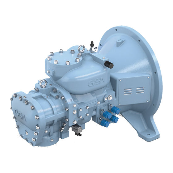
GEA Grasso M-Series Operating Manual (88 pages)
Screw Compressor Packages
Brand:
GEA
| Category:
Air Compressor
| Size: 18 MB
Table of Contents
Step
2
Step
3
Table of Contents
5
1 Basics
11
Importance of the Documentation
11
Requirements for Personnel, Obligation to Exercise Due Care
11
Legal Foundations (Germany)
12
Specified Use
14
Warning against Foreseeable Abusive Use
14
CE Mark
15
Fig. 1 CE Mark
15
2 Manufacturer Information
16
3 Customer Service
17
Technical Customer Service Department
17
Spare Parts
17
Training Courses
17
Service Contracts
17
4 Safety
18
General Information for Safety
18
Behaviour in the Case of Emergency
18
Possible Residual Hazards
18
Installation in Explosive Atmospheres, Installation Zones 1 and
19
5 Transport, Storage
21
General Instructions
21
Delivery
21
Transport (Crane Transport)
21
Fig. 2 Designation of the Lifting Points
21
Fig. 3 Stopper with Shackle
22
Fig. 4 Transportation with a Wire Rope Hoist
22
Bearings
23
Fig. 5 Transportation Using Crossbeam
23
Storage (Several Years)
24
6 Installation
26
Basic Information for Installation
26
Rigid Installation
26
Anti-Vibration Mounting
26
Electrical Connection
26
Use in Explosive Atmospheres, Installation Zones 1 und
27
Sound Insulation, Weather Protection
27
Information Regarding Noise Emissions
27
7 Description of Design and Function
29
Installation in Explosive Atmospheres, Installation Zones 1 und
29
Product Code of Screw Compressor Packages - Grasso SP1, SP2, Spduo and M Series
30
Technical Specifications
32
Location of the Product Identification (Name Plate)
33
Fig. 6 Location of the Product Identification (Type Plate)
33
Fig. 7 Type Plate
33
Information and Safety Labels on the Product
34
Labelling of the Pressure and Temperature Sensors, Heater
34
Label of the Safety Valve
34
Labels of the Screwed Connections with Dinova Ring
34
Fig. 8 Safety Labels of the Pressure and Temperature Sensors, Heater
34
Fig. 9 Label of the Safety Valve
34
Fig. 10 Labels of the Screwed Connections
34
Labels of the Pipelines
35
Marking the Direction of Rotation of the Compressor Drive Motor
35
Marking the Direction of Rotation of the Oil Pump Motor
35
Fig. 11 Labels of the Pipelines
35
Fig. 12 Marking the Direction of Rotation of the Compressor Drive Motor
35
Fig. 13 Marking the Direction of Rotation of the Oil Pump Motor
35
Labels of the Pressure Gauge
36
Labeling of the Control / Control Cabinet
36
Fig. 14 Labels of the Pressure Gauge
36
Fig. 15 Test Verification for the Control System
36
Designation of the Earth Connection
37
Process Flow Diagram
37
Fig. 16 Designation of the Earth Connection
37
Fig. 17 Process Flow Diagram Grasso SP1, M-Series
37
Main Components
38
Fig. 18 Main Components of the GEA Grasso M-Series
38
Compressor Drive Motor
39
Fig. 19 GEA Grasso M-Series, Arrangement of the SCP
39
Fig. 20 GEA Grasso M-Series, Arrangement of the Compressor Drive Motor
39
Screw Compressor
39
Compressor with Coupling Housing
40
Fig. 21 GEA Grasso M-Series, Arrangement of the Coupling Housing
40
Fig. 22 GEA Grasso M-Series, Arrangement of the Oil Separator
40
Oil Separator
40
Fig. 23 GEA Grasso M-Series, Arrangement of the OMC Block with Oil Filter System
41
Fig. 24 GEA Grasso M-Series, Arrangement of the Oil Cooler
41
Oil Cooler
41
Oil Pump (Optional)
41
OMC Block with Oil Filter System
41
Fig. 25 GEA Grasso M-Series, Arrangement of the (Optional) Oil Pump
42
Fig. 26 GEA Grasso M-Series, Suction Filter - Check Valve Combination
42
Suction Filter - Check Valve Combination
42
Controller
43
Fig. 27 GEA Grasso M-Series, Arrangement of the Controller
43
Fittings
43
Safety Devices
44
Components Installed by the Client
45
Monitoring Devices
45
General Functional Description
45
Refrigerant Circuit
45
Oil System
46
Oil Separation
46
Oil Heater
46
Oil Cooling
46
Oil Filter
46
Oil Pump
46
Oil Injection
47
Oil Circuit, OMC Block
47
Capacity Control
47
Technical Specifications
47
Designed for Use in Explosive Atmospheres
47
Basic Terms
48
Operating Media
48
Refrigerant
48
Refrigeration Machine Oils
48
Secondary Refrigerant
48
Operating Limits
48
Water Quality Requirements, Parameters
50
Fig. 28 Corrosion Resistance in Presence of Chlorides
51
8 Start-Up
53
Important Information for Start-Up
53
Basics
54
Connecting the Screw Compressor Package
54
Connecting the Pipes
54
Electrical Connection
55
Paint and Insulation
55
Start-Up Procedure
55
Checking the Electrical Connection
55
Leak Test
55
Drying, Vacuum
56
Fig. 29 Vacuum Required to Remove Moisture from Refrigerating Plants
56
Operating Position of Valves
57
Fig. 30 Stop Valve Open
57
Fig. 31 Stop Valve Closed
57
Fig. 32 Check Valve
57
Fig. 33 Shuttable Check Valve
57
Fig. 34 Control Valve
58
Fig. 35 Shuttable Check Valve
58
Fig. 36 Solenoid Valve
58
Fig. 37 Change-Over Valve
58
Fig. 38 Oil Pressure Control Valve
58
Fig. 39 Overflow Valve, Safety Valve
59
Fig. 40 Pressure Controlled Check Valve
59
Fig. 41 Quick Acting Valve, Spring-Loaded
59
Fig. 42 Charging Valve, Drain Valve
59
Fig. 43 Service Valve
59
Oil Charge
60
Pressure Compensation with the Cooling System
60
Checking the Direction of Rotation of the Oil Pump Motor
60
Fig. 44 Oil Temperature Limiter
60
Fig. 45 Temperature Controlled Control Valve
60
Checking the Fault Monitoring
61
Checking of the Safety Pressure Limiter
61
Checking of the Emergency-OFF Button
61
Adjustment of Oil Pressure
62
Checking the Direction of Rotation of the Drive Motor
62
Mounting the Coupling
62
Fig. 46 Motor Direction of Rotation
62
Checking the Water Circuits
63
Initial Start-Up
63
Checking the Adjustment of the Control Slide
63
Checking the Control Slide Adjustment Times
63
Checking the Oil Cooler
63
Adjusting the Amount of Injection Oil and the Oil Temperature
63
Screw Compressor Packages Without Refrigerant Injection
64
Compressor Units with Refrigerant Injection
64
Start-Up after Long Standstill Periods
64
Restarting after Approx. 1 Year Standstill
64
9 Use, Operation, Control
65
Use in Explosive Atmospheres, Installation Zones 1 and
65
Important Information for the Operator
65
Prerequisite for Switching on
65
Overview of the Operating Modes
67
Setting of Setpoint and Limiting Values as Well as Safety Devices
69
Operation of the Screw Compressor Package
69
Instructions Regarding Failures, Their Causes and Remedies
69
10 Cleaning, Maintenance, Repair
72
Use in Explosive Atmospheres, Installation Zones 1 and
72
Important Information for Service Personnel
72
Cleaning the Heat Exchanger
72
Mechanical Cleaning
73
Chemical Cleaning
73
Maintenance
73
General Instructions
73
Repair Work
74
Repair Information
74
Repairs of Pressure Vessels Subject to Approval Inspection
74
Maintenance Intervals
74
Maintenance Work
74
Maintenance of the Screw Compressor
74
Changing the Block Mounting Filter Element
75
Replacing the Oil Filter
75
Maintenance of the Suction Filter
76
Oil Draining, Oil Filling, Oil Change
76
Oil Pump Maintenance
78
Changing the Fine Oil Separation Cartridges
78
Fig. 47 Arrangement of MIN / MAX Sight Glasses
78
Tightening Screw Fastenings
79
Coupling Maintenance
79
Checking the Function of Check Valves
79
Searching for Leaks on the Refrigerant Side / Leak Test
79
Fig. 48 Operating Position of the Fine Oil Separation Cartridges
79
Venting the Refrigerant Circuit
80
Refrigerant Evacuation
80
Checking the Bearing Noise
81
Checking the Solenoid Valves for Capacity Control
81
Checking the Oil Heater
81
Maintenance of the Compressor Drive Motor
81
Checking the Start Regime
81
Checking the Safety Devices
81
Checking the Operating Parameters
81
Maintenance of the Switching Cabinet
82
Checking the Earth Connection
83
Insulation
83
Check of the Tightening Torque on the Adjusting Elements of the Fixing Base
83
11 Decommissioning
84
Shut-Down in the Event of Dangerous Situations
84
Standstill for a Period <48 Hours
84
Measures During Shutdowns
84
Monthly Measures During Standstill
85
Four Weeks before Restarting
85
12 Decommissioning, Disposal
86
Advertisement
Advertisement
Related Products
GEA Grasso
GEA Grasso VHS Series
GEA Grasso V Series
GEA GTR03BL series
GEA GSC TP
GEA GBE Series
GEA GBS Series
GEA GKE Series
GEA GKH Series
GEA GSC
GEA Categories
Control Unit
Air Compressor
Water Pump
Compressor
Industrial Equipment
More GEA Manuals
Login
Sign In
OR
Sign in with Facebook
Sign in with Google
Upload manual
Upload from disk
Upload from URL