Table of Contents
Advertisement
Quick Links
Advertisement
Table of Contents

Subscribe to Our Youtube Channel
Related Manuals for GEA HG8 Series


Summary of Contents for GEA HG8 Series
- Page 1 Bock Compressor HG8 Assembly instructions HG8/2470-4 HG8/2470-4 S HGX8/2470-4 HGX8/2470-4 S HG8/2830-4 HG8/2830-4 S HGX8/2830-4 HGX8/2830-4 S HG8/3220-4 HG8/3220-4 S HGX8/3220-4 HGX8/3220-4 S engineering for a better world GEA Refrigeration Technologies...
- Page 2 About these instructions Read these instructions before assembly and before using the compressor. This will avoid misunder- standings and prevent damage. Improper assembly and use of the compressor can result in serious or fatal injury. Observe the safety instructions contained in these instructions. These instructions must be passed onto the end customer along with the unit in which the compres- sor is installed. Manufacturer GEA Bock GmbH 72636 Frickenhausen Contact GEA Bock GmbH Benzstraße 7 72636 Frickenhausen Germany Telephone +49 7022 9454 0 Fax +49 7022 9454 137 bock@gea.com www.bock.de...
-
Page 3: Table Of Contents
Contents Page Safety 1.1 Identification of safety instructions 1.2 Qualifications required of personnel 1.3 General safety instructions 1.4 Intended use Product description 2.1 Short description 2.2 Name plate 2.3 Type key Areas of application 3.1 Refrigerants 3.2 Oil charge 3.3 Limits of application Compressor assembly 4.1 Setting up 4.2 Pipe connections 4.3 Pipes 4.4 Laying suction ans pressure lines 4.5 Operating the shut-off valves 4.6 Operating mode of the lockable service connections Electrical connection 5.1 Information for contactor and motor contactor selection... -
Page 4: Safety
1| Safety 1.1 Identification of safety instructions: Indicates a dangerous situation which, if not DANGER! avoided, will cause immediate fatal or serious injury. Indicates a dangerous situation which, if not WARNING! avoided, may cause fatal or serious injury. Indicates a dangerous situation which, if not CAUTION! avoided, may cause fairly severe or minor injury. Indicates a situation which, if not ATTENTION! avoided, may cause property damage. INFO! Important information or tips on simplifying work. 1.2 Qualifications required of personnel WARNING! I nadequately qualified personnel poses the risk of accidents, the consequence being serious or fatal injury. Work on compressors must therefore only be performed by personnel with the qualifica- tions listed below: • F or example, a refrigeration technician, refrigeration mechatron-... -
Page 5: Intended Use
1| Safety 1.4 Intended use These assembly instructions describe the standard version of the HG8 manufactured by Bock. The compressor is intended for use in refrigeration systems in compliance with the limits of application. Only the refrigerant specified in these instructions may be used. Any other use of the compressor is prohibited! WARNING! The compressor may not be used in potentially explosive environments! The Bock refrigerating compressor named in the title is intended for installing in a machine (within the EU according to the EU Directives 2006/42/EC Machinery Directive, 97/23/EC Pressure Equipment Directive and 2006/95/EC – Low Voltage Directive). Commissioning is only permissible if the compressor has been installed in accordance with these a ssembly instructions and the entire system into which it is integrated has been inspected and a pproved in accordance with legal regulations. -
Page 6: Product Description
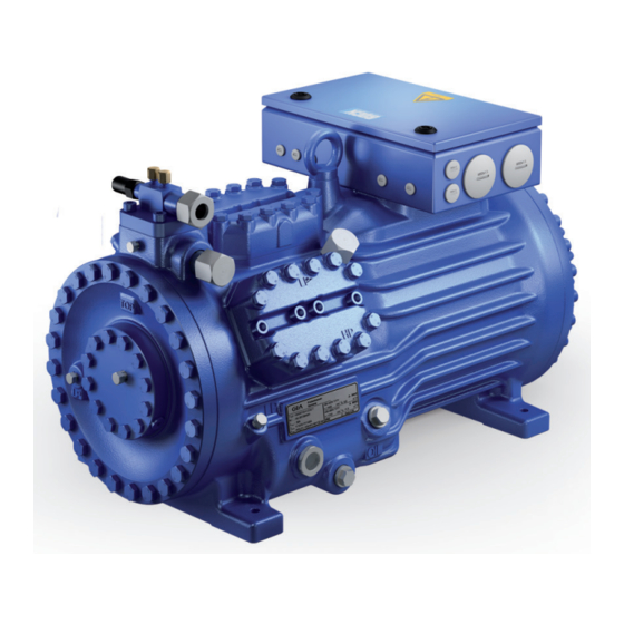
2| Product description 2.1 Short description • Semi-hermetic eight-cylinder reciprocating compressor with suction-gas cooled drive motor. • The stream of refrigerant sucked out of the evaporator flows over the motor and cools it intensively. In this way, the motor can be kept at a relatively low temperature level, particularly under high loads. Suction shut- Terminal box off valve Transport eyelet Cylinder cover Valve plate Motor section Discharge shut-off valve Drive section Oil pump Name plate Oil sight glass Fig. 1 Dimension and connection values can be found in Chapter 10... -
Page 7: Type Key
2| Product description 2.2 Name plate (example) GEA Bock GmbH 72636 Frickenhausen, Germany HGX8/3220-4 AS12345-A018 SE 55 Fig. 2 Type designation Voltage, circuit, frequency 50 Hz Machine number Nominal rotation speed maximum operating current Displacement Starting current (rotor blocked) Voltage, circuit, frequency 60 Hz Δ: Part winding 1 10 Nominal rotation speed YYY: Part windings 1 and 2 11 Displacement ND (LP): max. admissible operating pressure 12 Oil type filled at the factory (g) Low pressure side... -
Page 8: Areas Of Application
3| Areas of application 3.1 Refrigerants • HFKW / HFC: R134a, R404A/R507, R407C • (H)FCKW / (H)CFC: 3.2 Oil charge The compressors are filled at the factory with the following oil type: - for R134a, R404A/R507, R407C FUCHS Reniso Triton SE 55 - for R22 FUCHS Reniso SP 46 Compressors with ester oil charge (FUCHS Reniso Triton SE 55) are marked with an X in the type designation (e.g. HGX8/3220-4). INFO! For refilling, we recommend the above oil types. Alternatives: see lubricants table, Chapter 7.4. ATTENTION! The oil level must be in the visible part of the sight glass; damage max. oil level to the compressor is possible if min. oil level... - Page 9 Unlimited application range Supplementary cooling or reduced suction gas temperature R134a Supplementary cooling and reduced suction gas temperature Motor version S (more powerful motor) Fig. 4 Evaporation temperature (°C) Condensing temperature (°C) Suction gas superheat (K) Suction gas temperature (°C) HGX8/2470-4 - HGX8/2830-4 - R407C HGX8/3220-4 max. evaporating temperature = 0 °C Maximum admissible operating pressure (g) High pressure side (LP/HP): Fig. 5 19/28 bar LP = Low pressure HP = High pressure Design for other areas on request R404A/R507 HGX8/2830-4...
-
Page 10: Compressor Assembly
4| Compressor assembly INFO! New compressors are factory-filled with inert gas (3 bar nitrogen). Leave this service charge in the compressor for as long as possible and prevent the ingress of air. Check the compressor for transport damage before starting any work. 4.1 Setting up Use transport eyelet. Do not lift manually! Use lifting gear! Fig. 8 Provide adequate clearance for maintenance work. -
Page 11: Pipes
4| Compressor assembly Pipe connections on the compressor are available for soldering or welding (accessories). The discharge and suction line valves have graduated inside diameters so that pipes with standart millimetre and inch dimensions can be used. The pipe will be immersed more or less deeply according to dimension. The connection diameters of the shut-off valves are rated for maximum compressor output. The actual required pipe cross section must be Fig. 13: graduated matched to the output. The same applies for non-return valves. internal diameter 4.3 Pipes Pipes and system components must be clean and dry inside and free of scale, swarf and layers of rust and phosphate. Only use air-tight parts. Lay pipes correctly. Suitable vibration compensators must be provided to prevent pipes being cracked and broken by severe vibrations. -
Page 12: Operating The Shut-Off Valves
4| Compressor assembly 4.5 Operating the shut-off valves Before opening or closing the shut-off valve, release the valve spindle seal by approx. ¼ of a turn counter-clockwise. After activating the shut-off valve, re-tighten the adjustable valve spindle seal clockwise. Release Tighten Valve spindle seal Fig. 16 Fig. 15 4.6 Operating mode of the lockable service connections Service connec- tion closed Pipe connection Spindle Connection blocked Compressor Fig. 17 Opening the shut-off valve: Spindle: turn to the left (counter-clockwise) as far as it will go. —> Shut-off valve completely opened / service connection closed. Service connec- tion opened Pipe connection Spindle Connection open Compressor Fig. 18 Opening the service connection... -
Page 13: Electrical Connection
5| Electrical connection Electrical connection DANGER! H igh voltage! Risk of electric shock! Only carry out work when the electrical system is disconnected from the power supply! INFO! C onnect the compressor motor in accordance with the circuit diagram (see inside of terminal box). U se suitable cable entry point of the correct protection type (see name plate) for routing cables into the terminal box. I nsert the strain reliefs and prevent chafe marks on the cables. -
Page 14: Standard Motor, Design For Direct Or Partial Winding Start
5| Electrical connection 5.2 Standard motor, design for direct or partial winding start Designation on the name plate Sticker on the terminal box ∆/YYY Compressors with this marking are suitable for direct or partial winding start. The motor winding is subdivided into two parts: Partial winding 1 = 60% and part winding 2 = 40%. This winding d ivision reduces the start-up current needed for a part winding start to approx. 65% of that for a direct start. INFO! A mechanical unloaded start with bypass solenoid valve is not required. - Page 15 ührung für Direkt- oder Teilwicklungsstart t dieser Kennzeichnung ist für Direkt- Typschildangabe Gelber Aufkleber am Klemmenkasten chter mit dieser Kennzeichnung ist für Direkt- klungsstart (PW-Anlauf) geeignet. am Klemmenkasten ∆/YYY Teilwicklungsstart (PW-Anlauf) geeignet. in zwei Teilwicklungen unterteilt: Teil- ∆/YYY Motor ist in zwei Teilwicklungen unterteilt: Teil- 5| Electrical connection 0% und Teilwicklung 2=40%.
- Page 16 5.3 Basic circuit diagram for part winding start with standart motor F1.2 F1.1 I=33% I=66% I> I> I> I> I> I> F1.1 F1.2 X SS X1 L1 L1 N N 43 43 11 /YYY X2 1 MP10 P - oil Compressor terminal box Anschlußkasten Verdichter R2.1 R2.2 R2.3...
- Page 17 L1.1 L2.1 L3.1 L1.2 P> P< P-Öl B1 Release switch (thermostat) Q1 Main switch M1 Compressor motor K1 Mains contactor (part winding 1) K2 Mains contactor (part winding 2) K1T Delay relay max. 1s E1 Oil sump heater S1 Control voltage switch XSS Terminal strip in the external switch cabinet PW MP10 BOCK COMPRESSORS...
- Page 18 5| Electrical connection 5.4 Sondermotor: Ausführung für Direkt- oder Stern-Dreieck-Anlauf 5.4 Special motor: design for direct or star-delta start Für den Stern-Dreieck-Anlauf ist eine mechanische Anlaufentlastung mit Bypass-Magnetventil A mechanical unloaded start with bypass solenoid valve (accessories) is required for the (Zubehör) erforderlich. star-delta start. Bezeichnung auf dem Typschild Aufkleber auf Klemmenkasten Designation on the name plate Sticker on the terminal box ∆...
- Page 19 5| Electrical connection Star-delta start-up is only possible for ∆ 230 V power supply. Example: 230 V Δ 400 V Y Direct start only Direct start Star-delta-start In the factory the motor is wired for direct starting at high voltage. The brides are to be removed for star delta starting at low voltage.
- Page 20 5.5 Circuit diagram for star-delta start 230 V ∆ / 400 V Y F1.2 F1.1 I=33% I=66% I> I> I> I> I> I> F1.1 F1.2 X SS ˜ X1 L1 L1 N N 43 43 11 X2 1 MP10 Compressor terminal box Anschlußkasten Verdichter R2.1 R2.2...
- Page 21 L1.1 L2.1 L3.1 L1.2 P> P< P-Öl Q1 Main switch M1 Compressor motor K1 Mains contactor Δ-contactor K2 K3 Y-contactor K1T Delay relay max. 1s K4T Delay relay for contactor switchover E1 Oil sump heater S1 Control voltage switch XSS Terminal strip in the external switch cabinet PW MP10 BOCK COMPRESSORS...
-
Page 22: Electronic Trigger Unit Mp
5| Electrical connection 5.6 Electronic trigger unit MP 10 The compressor motor is fitted with cold conductor temperature sensors (PTC) connected to the electronic trigger unit MP 10 in the terminal box. Readiness to operate is signalled by the H3 LED (green) after the power supply is applied. In the case of excess temperature in the motor winding, the unit switches off the compressor and the H1 LED lights red. The hot gas side of the compressor can also be protected against overtemperature using a thermal protection thermostat (accessory). The H2 LED (red) is provided for the protection function. The unit trips when an overload or inadmissible operating conditions occur. Find and remedy the cause. -
Page 23: Functional Test Of The Trigger Unit Mp
5| Electrical connection 5.8 Function test of the trigger unit MP 10 Before start-up, troubleshooting or making changes to the control power circuit, check the functionality of the trigger unit: LED H1 LED H2 LED H3 Procedure green • Interrupt power supply (L1 or S1) • Release the motor temperature sensor connection (1 or 2) • Release the hot gas temperature sensor (if installed) (3 or 4) • Restore the power supply (L1 or S1) •... -
Page 24: Oil Sump Heater (Accessories)
5 | Electrical connection 5.9 Oil sump heater (accessories) When the compressor is at a standstill, refrigerant diffuses into the lubricating oil of the compressors housing, depending on pressure and ambient temperature. This reduces the lubricating capacity of the oil. When the compressor starts up, the refrigerant contained in the oil evaporates out throught the reduction in pressure. The consequences can be foaming and migration of the oil, causing oil shocks under certain circumstances. Operation: The oil sump heater operates when the compressor is at a standstill. When the compres- sor starts up, the oil sump heater switches off again automatically. Connection: The oil sump heater must be connected via an auxiliary contact (or parallel wired auxili- Anschlussschema für Ölsumpfheizung ary contact) of the compressor contactor to a seperate electric circuit. Connection diagramm for oil sump heater El. data: 230 V - 1 - 50/60 Hz, 200 W. Plan de raccordement pour résistance de carter d‘huile Fig. 22 ATTENTION! Connection to the current path of the safety control chain is not permitted... -
Page 25: Commissioning
6| Commissioning 6.1 Preparations for start-up INFO! In order to protect the compressor against inadmissible operating conditions, high-pressure and low-pressure pressostats controls are mandatory on the installation side. The compressor has undergone trials in the factory and all functions have been tested. There are therefore no special running-in instructions. Check the compressor for transport damage! 6.2 Pressure strength test DANGER! Bursting! The compressor must only be pressurised using nitrogen ). -
Page 26: Avoid Slugging
6| Commissioning 6.5 Refrigerant filling CAUTION! Wear personal protective clothing such as goggles and protective gloves! Make sure that the suction and pressure line shut-off valves are open. With the compressor switched off, add the liquid refrigerant directly to the condenser or receiver, breaking the vacuum. If the refrigerant needs topping up after starting the compressor, it can be topped up in vapour form on the suction side, or, taking suitable precautions, also in liquid form at the inlet to the evaporator. INFO! Avoid overfilling the system with refrigerant! I n order to prevent shifts in concentration, zeotropic refrigerant blends (e.g. R407C) must always only be added to the refrigerating system in liquid form. -
Page 27: Connection Of Oil Level Regulator
6| Commissioning 6.8 Connection of oil level regulator Oil level regulation systems have proven themselves with parallel circuits of several compressors. The connection "0" is provided for installing an oil level regulator (see dimensions drawing). All common oil level regulators from AC&R, ESK and Carly as well as the OM3 TraxOil oil level regulation system from Alco can be connected directly without adapters (see Fig. 21). A sight glass on the oil level regulator is not required. Anschluss Ölspiegelregulator Bei Verbundschaltungen von mehreren Verdichtern haben sich Ölstandsregulierungssysteme bewährt. Für die Montage eines Ölspie- M6 x 10 gelregulators ist der Anschluss „O“ vorgesehen (siehe Maßzeichnung). je 3 mal 3 times each Alle gängigen Ölspiegelregulatoren von AC&R, ESK sowie das elek-... -
Page 28: Extract From The Lubricants Table
7| Maintenance 7.3 Recommended spare parts HG8 / ... 2470-4 (S) 2830-4 (S) 3220-4 (S) Item No. Item No. Item No. Designation Set of gaskets kit 80235 Valve plate kit 80199 Oil pump kit 80290 Oil sump heater kit (220-240 V) 80237 Only use genuine Bock spare parts! 7.4 Extract from the lubricants table The oil type filled as standard in the factory is marked on the name plate . This oil type should be used as a preference. Alternatives are stated in the extract from our lubricants table below. -
Page 29: Accessories
8| Accessories 8.1 Start unloader (kit- Item No. 08981) A start unloader is necessary for Y/Δ start (special motor). • Fit the non-return valve in the discharge pipe • Rate the non-return valve according to the operating conditions. • Electrical trigger for the solenoid valve: closed idle • Cylinder cover for start unloader is marked Oil pump „SU“ (start unloader) Fig. 24 WARNING! The start unloader must only run during the start-up phase, approx. 5 seconds before to max. 5sendons after thr compressor starts. Otherwise there is a risk of overheating from bypass operation INFO! A start unloader is not required for part winding start (PW start, standart motor). -
Page 30: Capacity Controller (Item No. 08821)
8| Accessories 8.4 Capacity controller ( Item No. 08821) „N“ Oil pump Fig. 27 Fig. 28 Fig. 29 The standart compressor ist To fit a capacity controller, Screw in capacity controller prepared for being equipped remove bung „N" from the with sealing ring. with three capacity controllers. cover Torque: 60 Nm! WARNING! Several capacity controllers cannot switch at the same time during compressor operation! Otherwise the sudden change in load can damage the compressor! Comply with the switching interval of 60 s. -
Page 31: Technical Data
9| Technical data 380-420 V Δ/YYY - 3 - 50 Hz PW 440-480 V Δ/YYY - 3 - 60 Hz PW PW = Part Winding Winding ratio : 60% / 40%... -
Page 32: Dimensions And Connections
10| Dimensions and connections Massenschwerpunkt ca.580 Massenschwerpunkt Massenschwerpunkt B B1 ca.580 Massenschwerpunkt ca.580 Centre of gravity ca.580 B B1 A1 B B1 Massenschwerpunkt B B1 A1 ca.580 B B1 A1 ÖV 13,5 ca.350 ÖV1 ÖV1 13,5 13,5 ca.350 ca.350 ÖV 13,5 ca.350 ÖV1 13,5 ca.350... - Page 33 10| Dimensions and connections Suction line see technicla data, Chapter 9 Discharge line Connection suction side, not lockable 8 “ NPTF Connection suction side, lockable 16 “ UNF Connection suction side, not lockable 4 “ NPTF Connection discharge side, not lockable 8 “ NPTF Connection discharge side, lockable 16 “ UNF Connectoin oil pressure switch OIL 16 “ UNF Connection oil pressure switch LP 16 “ UNF Connection oil return from oil separator 4 “ NPTF Connection oil pressure gauge 16 “...
-
Page 34: Declaration Of Conformity And Installation
11| Declaration of conformity and installation DECLARATION OF CONFORMITY CE 03 for using the compressors within the European Union (in accordance with Low Voltage Directive 2006/95/EC) We hereby declare that the following refrigerating compressors Product designation: HG8 comply with the Low Voltage Directive 2006/95/EC. Applied harmonised standard: EN 60034-1:2010 EN 60204-1:2006 DECLARATION OF INSTALLATION for using the compressors within the European Union (in accordance with Machinery Directive 2006/42/EC) The manufacturer: GEA Bock GmbH, Benzstraße 7 72636 Frickenhausen, Tel.: 07022/9454-0 hereby declares that the refrigerating compressor HG8 complies with the basic requirements of Appendix II 1B of the Machinery Directive 2006/42/EC. Applied harmonised standard: EN 12693:2008 and the corresponding standards referenced A partly completed machine may only be put into operation when it has been established that the machine, into which the partly completed machine is to be installed, conforms to the r egulations of the Machinery Directive (2006/42/EC). The manufacturer undertakes to transmit electronically the special documentation required by individual states for partly completed machinery on request. The special technical documentation required for partly completed machinery has been created in accordance with Appendix VII Part B. -
Page 35: Service
11| Service Dear customer, Bock compressors are top-quality, reliable and service-friendly quality products. If you have any questions about installation, operation and accessories, please contact our technical service or specialist wholesaler and/or our representative. The Bock service team can be contacted by phone with a toll-free hotline 00 800 / 800 000 88 or via e-mail: bock@gea.com. Yours faithfully GEA Bock GmbH Benzstraße 7 72636 Frickenhausen Germany We also provide information on the Internet at www.bock.de. For example, under the "Documentation" link you will find: - Technical information - Product information - Product brochures - and much more... - Page 36 • • GEA Group is a global engineering company with multi-billion euro sales and operations in more than 50 countries. Founded in 1881, the company is one of the largest providers of innovative equipment and process technology. GEA Group is listed in the STOXX® Europe 600 index.
Need help?
Do you have a question about the HG8 Series and is the answer not in the manual?
Questions and answers