
Subscribe to Our Youtube Channel
Related Manuals for SIGLENT SDS1000CML+


Summary of Contents for SIGLENT SDS1000CML+
- Page 1 User Manual SDS1000CML+/SDS1000DL+ Digital Oscilloscope UM0101A-E01A SIGLENT TECHNOLOGIES CO,.LTD...
- Page 3 SIGLENT Declaration Copyright © by SIGLENT TECHNOLOGIES CO,.LTD. All rights reserved. Contents in this Manual are not allowed to copy, extract and translate before being allowed by SIGLENT. SDS1000CML+/SDS1000DL+ User Manual I...
-
Page 4: Brief Introduction
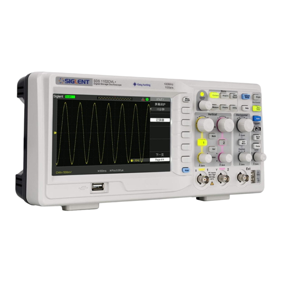
SIGLENT Brief Introduction Characteristic: ● The volume of the oscilloscope is cabinet and it is portable ● 7” Color TFT LCD display ● 2 channels, Bandwidth: 40MHz-150 MHz ● Single real-time sampling rate is: 1Gsa/s; Equivalent sampling rate is 50GSa/s. - Page 5 SIGLENT General Safety Summary Carefully read the following safety precautions to avoid person injury and prevent damage to the instrument and any products connected to it. To avoid potential hazards, please use the instrument as specified. Only qualified technician should perform service procedures...
- Page 6 SIGLENT If the equipment is used in a manner not specified by the manufacturer, the protection provided by the equipment may be impaired. This product has been tested to the requirements of CAN/CSA-C22.2 No. 61010-1, second edition, including Amendment 1, or a later version of the same standard incorporating the same level of testing requirements.
- Page 7 SIGLENT Safety Terms and Symbols Terms used on the instrument. Terms may appear on the instrument: DANGER: Indicates an injury or hazard that may be immediately happen. WARNING: Indicates an injury or hazard that may be not immediately happen. CAUTION: Indicates that a potential damage to the instrument or other property might occur.
-
Page 8: Table Of Contents
SIGLENT Content Brief Introduction ....................II Chapter 1 Accidence ....................1 1.1 Accidence of Panel and Display Information ............2 1.2 Function Checking ....................5 Probe ........................7 1.3.1 Probe Safety ....................7 1.3.2 Probe Attenuation Setting ................7 1.3.3 Probe Compensation .................. 8 Chapter 2 Functions Instruction and Operation .............9... - Page 9 3.1 Prompting Messages: ................... 108 3.2 Troubleshooting ....................110 Chapter 4 Service and Support ................112 4.1 Maintain Summary ....................112 4.2 Contact SIGLENT ....................113 Appendix A: Default Setup ................. 114 Appendix B: Daily Maintain and Cleaning ............116 SDS1000CML+/SDS1000DL+ User Manual VII...
-
Page 11: Chapter 1 Accidence
SIGLENT Chapter 1 Accidence SDS1000CML+ /SDS1000DL+ Series Digital Oscilloscope is mini-type and portable bench type instruments, which could be used for measuring as the GND voltage. This Chapter shows you how to operate following tasks: ◆ Accidence of panel and Display information ◆... -
Page 12: Accidence Of Panel And Display Information
SIGLENT 1.1 Accidence of Panel and Display Information 1.1.1 Front Panel It is important for you to understand the DSO’s front panel before operating it. The following contents are the brief introduction for the front panel function, which is useful to be familiar with the operation of the SDS1000CML+/SDS1000DL+ Series Digital Storage Oscilloscope in short time. - Page 13 SIGLENT Description Description Power button Trigger Control Area Menu On/Off Probe Compensation Universal Knob Horizontal Control Area Functions Menus Ext Trigger Terminal Default Setup Vertical Control Area Help button Channel Input Terminal Single Trigger Print key Run/Stop Control Menu Softkey...
- Page 14 SIGLENT 1.1.3 User display interface Picture 1.1-3 1.Product Logo Siglent is the registered trademark of our company. 2. Trigger status Armed. The oscilloscope is acquiring pre-trigger data. All triggers are ignored in this state. Ready. All pre-trigger data has been acquired and the oscilloscope is ready to accept a trigger.
-
Page 15: Function Checking
SIGLENT waveform. 6. Show the LAN port. Indicates the LAN port is connected. Indicates the LAN port is disconnected. 7. Show the Channel symbol. 8. Readout shows trigger signal frequency.. 9. Readout shows the trigger level value and trigger type.. - Page 16 SIGLENT Picture 1.2-2 3.Press “AUTO” to show the 1 KHz frequency and about 3V peak-peak square wave in couple seconds Picture 1.2-3 4. Press “CH1” two times to cancel the channel 1, Press“CH2” to change screen into channel 2, reset the channel 2 as step 2 and step 3.
-
Page 17: Probe
SIGLENT 1.3 Probe 1.3.1 Probe Safety A guard around the probe body provides a finger barrier for protection from electric shock. Picture 1.3-1 Connect the probe to the oscilloscope and connect the ground terminal to ground before you take any measurements. -
Page 18: Probe Compensation
SIGLENT 1.3.3 Probe Compensation As an alternative method to Probe Check, you can manually perform this adjustment to match your probe to the input channel. Picture1.3-2 1. Set the Probe option attenuation in the channel menu to 10X. Set the switch to 10X on the probe and connect the probe to channel 1 on the oscilloscope. -
Page 19: Chapter 2 Functions Instruction And Operation
SIGLENT Chapter 2 Functions Instruction and Operation To use your oscilloscope effectively, you need to learn about the following oscilloscope functions: ◆ Menu and control button ◆ Connector ◆ Auto Setup ◆ Default Setup ◆ Universal knob ◆ Vertical System ◆... -
Page 20: Menu And Control Button
SIGLENT 2.1 Menu and Control Button Showing as the following picture: Picture 2-1 ■ Channel buttons (1, 2): Press a channel button to turn that channel ON or OFF and open the channel menu for that channel. You can use the channel menu to set up a channel. - Page 21 SIGLENT ■ FORCE: Use the FORCE button to complete the current waveform acquisition whether the oscilloscope detects a trigger or not. This is useful for Single acquisitions and Normal trigger mode. ■ SAVE/RECALL: Press to display the Save/Recall menu. You can use the...
-
Page 22: Connector
SIGLENT 2.2 Connector Picture 2-2 ■ Channel Connector (CH1, CH2): Input connectors for waveforms display. ■ EXT TRIG: Input connector for an external trigger source. Use the Trigger Menu to select the “Ext” or “Ext/5” trigger source. ■ Probe Component: Voltage probe compensation output and ground. Use to electrically match the probe to the oscilloscope input circuit. -
Page 23: Auto Setup
SIGLENT 2.3 Auto Setup The SDS1000CML+/SDS1000DL+ Series Digital Storage Oscilloscopes have a Auto Setup function that identifies the waveform types and automatically adjusts controls to produce a usable display of the input signal. Press the AUTO button, and then press the menu option button adjacent to the... -
Page 24: Default Setup
SIGLENT Table 2-2 Auto set the function item Function Setting Acquire Mode Adjusted to Sampling Display Format Display Type Set to Dots for a video signal, set to Vectors for an FFT spectrum; otherwise, unchanged Vertical Coupling Adjusted to DC or AC according to the input... -
Page 25: Universal Knob
SIGLENT 2.5 Universal Knob Picture 2-5 Universal Knob You can use the Universal knob with many functions, such as adjusting the holdoff time, moving cursors, setting the pulse width, Setting the Video Linage, adjusting the upper and lower frequency limit, adjust X and Y masks when using the pass/fail function etc. -
Page 26: Ch1, Ch2 Channel
SIGLENT 2.6.1 CH1, CH2 Channel Table 2-1 CH1, CH2 function menu 1: Option Setting Introduction DC passes both AC and DC components of the input signal. Coupling AC blocks the DC component of the input signal and attenuates signals below 10 Hz. - Page 27 SIGLENT Setting CH1, CH2 Channels Each channel has its own separate Menu. The items are set up separately according to each channel. 1. Choosing Coupling Take the CH1 for example; the tested signal is a sine wave signal with DC deflection: ●...
- Page 28 SIGLENT Set BW to 20MHz Picture 2.6-3 BW Limit Symbol 3. Adjust Sensitivity Vertical scale adjusting has Coarse and Fine two modes, Vertical sensitivity range is 2mV/div~10V/div scale. Take the CH1 for example: ● Press “CH1”→“Volts/Div”→“Coarse”. It is the default setting of Volts/Div, and it makes the vertical scaling in a 1-2-5-step sequence from 2mv/div, 5mv/div, 10mv/div to 10v/div.
- Page 29 SIGLENT 4. Setting Probe Attenuation In order to assort the attenuation coefficient, you need to response in the channel operation Menu. If the attenuation coefficient is 10:1, the input coefficient should be set to 10X, so that the mistake of the Volts/div information and measure testing should be forbidden.
- Page 30 SIGLENT 6. Using the Digital Filter Press “CH1”→“Next Page page1/3”→ “Filter”, display the digital filter menu. Select “Filter Type”, then select “Upper Limit” or “Lower Limit” and turn the “Universal” knob to adjust them. ● Press “CH1”→“Next Page page1/3”→ “Filter” →“Off”. Turn off the Digital Filter function.
-
Page 31: Using Vertical "Position" Knob And "Volt/Div" Knob
SIGLENT 2.6.2 Using Vertical “Position” Knob and “Volt/div” Knob ■ Vertical “POSITION” Knob 1. Use the Vertical “POSITION” knobs to move the channel waveforms up or down on the screen. This button’s resolution is variety as per the vertical scale. - Page 32 SIGLENT Table 2-7 MATH function instruction Operation Setting Introduction + CH1 waveform adds CH2 waveform. CH1+CH1 The channel 2 waveform is subtracted CH1-CH2 from the channel 1 waveform. - The channel 1 waveform is subtracted CH2-CH1 from the channel 2 waveform.
- Page 33 SIGLENT able 2-8 FFT function menu 1: Introduction FFT Option Setting Select this channel as the FFT source. Source CH1, CH2 Hanning Select FFT window types. Hamming Window Rectangular Blackman Changes the horizontal magnification of the FFT display. FFT ZOOM...
- Page 34 SIGLENT 3. Press “Source” button to select “CH1” or “CH2” according to input signal channel. 4. According to Nyquist law, turn the “S/div” knob to adjust the sampling rate (This parameter is displayed behind the time base parameter) is at least double than input signal frequency.
- Page 35 SIGLENT Table 2-10 FFT window instruction Window Speciality Satisfied Test content Best frequency Symmetric transients or resolution, worst bursts. magnitude resolution. Equal-amplitude sine waves Rectangulr This is essentially the with fixed frequencies. same as no window. Broadband random noise with a relatively slowly varying spectrum.
- Page 36 SIGLENT If you input a sine signal to channel 1, follow these steps: 1. Measure FFT Amplitude 1) Input a sine signal to channel 1, and press the “AUTO” button. 2) Press the “MATH” button to enter the “MATH” menu.
-
Page 37: Using Ref
SIGLENT Measure FFT Frequency Press the CURSOR button. Press the “Cursor Mode” button to select “Manual”. Press the “Type” option button to select “Time”. Press the “Source” option button to select “MATH”. Press the “CurA” option button, turn the “Universal” button to move Cursor A to the highest position of the FFT waveform. - Page 38 SIGLENT Press the Ref button to display the “Reference waveform menu”. Picture 2.6-13 Operation step: Press the “REF” menu button to display the “Reference waveform menu”. Press the “Source” option button to select input signal channel. Turn the vertical “POSITION” knob and “Volt/div” knob to adjust the vertical position and scale to conformable positions.
-
Page 39: Horizontal System
SIGLENT 2.7 Horizontal System As follow Picture, there are one button and two knobs in the HORIZONTAL area. S/div knob Horizontal position knob Picture 2.7-1 Table 2- 12 SDS1000CML Horizontal system function menu: Option Setting Description Turn on this function that main timebase... -
Page 40: Horizontal Control Knob
SIGLENT 2.7.1 Horizontal Control Knob You can use the horizontal controls to change the horizontal scale and position of waveforms. The horizontal position readout shows the time represented by the center of the screen, using the time of the trigger as zero. Changing the horizontal scale causes the waveform to expand or contract around the screen center. - Page 41 SIGLENT If you want to see a section of the waveform in detail, follow these steps: (1) Press the “HORI MENU” button to enter the “Horizontal menu”. (2) Turn the “S/div” knob to change the main timebase scale. (3) Press the “Delayed” option button to select “On”.
-
Page 42: Trigger System
SIGLENT 2.8 Trigger System The trigger determines when the oscilloscope starts to acquire data and display a waveform. When a trigger is set up properly, the oscilloscope converts unstable displays or blank screens into meaningful waveforms. There are three buttons and one knob in the Trigger area. See picture.2-29: LEVEL knob Picture 2.8-1... -
Page 43: Signal Source
SIGLENT The feature is very useful because you can see the events that led up the trigger point everything to the right of the trigger point is called posttrigger information the amount of delay range (pre-trigger and posttrigger information) available is dependent on the sweep speed selected. -
Page 44: Trigger Type
SIGLENT 2.8.2 Trigger Type The scopes have five trigger types: Edge, Video, Pulse, Slope, and Alternative. ■ Edge Trigger Use Edge triggering to trigger on the edge of the oscilloscope input signal at the trigger threshold. Table 2-13 Edge Trigger function Menu:... - Page 45 SIGLENT Table 2-14 Trigger Setup function menu Option Setting Explain Coupling Passes all components of the signal Blocks DC components ,attenuates signals below 50 Hz. Attenuates the high-frequency components HF Reject above 150 kHz. Blocks the DC component , attenuates the LF Reject low-frequency components below 7...
- Page 46 SIGLENT Auto: The waveform refresh at a high speed whether the trigger condition is satisfied or not. Normal: The waveform refresh when the trigger condition is satisfied and waits for next trigger event occurring when the trigger condition is not satisfied.
- Page 47 SIGLENT ■ Pulse Trigger:Use Pulse Width triggering to trigger on aberrant pulses. Table 2-15 Pulse Trigger function Menu 1: Option Setting Explain Select the pulse to trigger Type Pulse pulse match trigger condition. Select input signal source. Source EXT/5 (Positive pulse width less...
- Page 48 SIGLENT Table 2-16 Pulse Trigger function Menu 2: Option Setting Explain Select the pulse to trigger the pulse match Type Pulse the trigger condition. Select the type of triggering; Normal mode is Auto best for most Pulse Width trigger Mode Normal applications.
- Page 49 SIGLENT ■ Video Trigger:Trigger on fields or lines of standard video signals. Table 2-17 Functional Manu of Video Trigger 1: Option Setting Instruction When you select the video type, put the couple set to the AC, then you could Type...
- Page 50 SIGLENT Picture 2.8-5 Operate Instruction 1. Set up Type 1) Press the “TRIG MENU” button to display “Trigger” menu. 2) Press the “Type” option button to select “Video”. 2. Set up Polarity Press the “Polarity” option button to select “...
- Page 51 SIGLENT ■ Slope Trigger:Trigger on positive slope of negative slope according to setup time of the oscilloscope. Table 2-19 Slope trigger function menu 1 Option Setting Instruction Trigger on positive slope of negative Type Slope slope according to setup time of the oscilloscope.
- Page 52 SIGLENT Table 2-20 Slope trigger function menu 2 Option Setting Instruction Trigger on positive slope of negative slope Type Slope according to setup time of the oscilloscope. Vertical Select the trigger level that can be adjusted by “LEVEL” knob. You can adjust “LEVEL A”, “LEVEL B”...
- Page 53 SIGLENT Press the “When” option button to select “ ”, “ ”, “ ”, ”,“ ”或 “ ”. “ Press the “Time” button, turn the “Universal” knob to adjust slope time. Press the “Next Page Page 1/2” option button to enter the second page of “Slope trigger menu”.
- Page 54 SIGLENT ■ Alternative trigger The trigger signal comes from two vertical channels when you use alternative trigger. In this mode, you can observe two irrelative signals at the same time. You can select different trigger types for two vertical signals, and selected types cover edge, pulse, video and slope trigger.
- Page 55 SIGLENT Table 2-22 Set trigger mode to pulse trigger function menu 1: Instruction Option Setting The trigger signal comes from two vertical Alternative channels when you use alternative trigger. In Type this mode, you can observe two irrelative signals at the same time.
- Page 56 SIGLENT Table 2-25 Set trigger mode to video trigger function menu 2: Option Setting Instruction Sync Line Num All lines Select appropriate video sync. Odd field Even Field Standard NTSC Select the video standard for sync and line Pal/Secam number count.
-
Page 57: Coupling
SIGLENT Operate Instruction: Observe two irrelative channel signals, follow these steps: 1. Input two irrelative signals to channel 1and channel 2. 2. Press the AUTO button. 3. Press the TRIG MENU button to enter “trigger menu”. 4. Press the “Type” option button to select “Alternative”. -
Page 58: Slope & Level
SIGLENT 2.8.5 Slope & Level The Slope and Level controls help to define the trigger. The Slope option (Edge trigger type only) determines whether the oscilloscope finds the trigger point on the rising or the falling edge of a signal. -
Page 59: Trigger Holdoff
SIGLENT 2.8.6 Trigger Holdoff You can use the Trigger Holdoff function to produce a stable display of complex waveforms. Holdoff is time between when the oscilloscope detects one trigger and when it is ready to detect another. The oscilloscope will not trigger during the holdoff time. -
Page 60: Acquiring Signals System
SIGLENT 2.9 Acquiring Signals System Showing as the follow picture, the “ACQUIRE” button for Acquiring Signals system is at the menu. Picture 2.9-1 Table 2-28 The Function manual of Acquiring Signals: Option Setting Introduction Use for sampling and accurately display most Sampling of the waveform. - Page 61 SIGLENT occur between samples. This can result in aliasing may cause narrow pulses to be missed. In these cases, you should use the Peak Detect mode to acquire data. Picture 2.9-2 Sampling modes ■ Peak Detect: Peak Detect mode capture the maximum and minimum values of a signal Finds highest and lowest record points over many acquisitions.
- Page 62 SIGLENT Average: The oscilloscope acquires several waveforms, averages them, and ■ displays the resulting waveform. Advantage: You can use this mode to reduce random noise Picture 2.9-4 Average Mode ■ Equivalent Time Sampling: The equivalent time sampling mode can achieve up to 20 ps of horizontal resolution (equivalent to 50GSa/s).
- Page 63 SIGLENT When you push the RUN/STOP or SINGLE buttons to start an acquisition, the oscilloscope goes through the following steps: 1). Acquire enough data to fill the portion of the waveform record to the left of the trigger point. This is also called the pre-trigger.
- Page 64 SIGLENT Operate Introduction: Set up Sampling Format You can press the “Acquisition” option button or turn the “Universal” knob to select “Sampling” mode, “Peak Detect” mode or “Average” mode.. Set up Averages When you select “Average” format, you can press the “Averages” option button to select “4”, “16”, “32”, “64”, “128”or “256”.
- Page 65 SIGLENT Set up Sampling Mode Press the “Mode” option button to select “Real Time” or “Equ Time”. Set up Sampling Rate Adjust the sampling rate by pressing the “Sa Rate” option button and turning the Time/div front panel knob. The sampling rate is shown at the corresponding timebase scale.
-
Page 66: Display System
SIGLENT 2.10 Display System The display function could be expressed by the “DISPLAY” Button. Picture 2.10-1 Table 2-29 Display system function menu 1: Option Setting Introduction Vectors fill the space between adjacent Vectors sample points in the display. Type There is no link between adjacent Dots sample points. - Page 67 SIGLENT Table 2-30 Display system function menu 2: Option Setting Introduction YT format displays the vertical voltage in relation to time (horizontal scale). XY Format format displays a dot each time a sample is acquired on channel 1 and channel 2 Normal Set to normal mode.
- Page 68 SIGLENT Operate Introduction: 1. Set up waveform display type 1) Press the “DISPLAY” button to enter the “Display” menu. 2) Press the “Type” option button to select “Vectors” or “Dots”. 2. Set up Persist Press “Persist” option button to select “Off”, “1 Sec”, “2 Sec”, “5Sec” or “Infinit...
-
Page 69: X-Y Format
SIGLENT 8. Set up Menu Display Press the “Menu Display” option button to select “2 sec”, “5sec”, “10sec”, “20sec” or “Infinite” to set menu display time on screen. 9. Set Skin Press the “skin” option button or turn the “Universal” knob to select “Classical”, “Modern”, “Traditional”... -
Page 70: Measure System
SIGLENT 2.11 Measure System The Oscilloscope displays the voltage in relation to time and test the wave form displayed. There are scale, Cursor and auto measure modes. 2.11.1 Scale Measurement This method allows you to make a quick, visual estimate. For example, you might look at waveform amplitude and determine that it is a little more than 100 mV. -
Page 71: Manual Mode
SIGLENT Manual Mode Table 2-32 Manual cursor function menu: Option Setting Instruction Cursor Mode Manual In this menu, set the manual cursor measure. Voltage Use cursor to measure voltage parameters. Type Time Use cursor to measure time parameters. Source MATH Select input signal channel. - Page 72 SIGLENT 7. The measurement values are displayed on the top of the left corner: If the measurement type is set to “Voltage”, the values are: The value of Cur A: CurA The value of Cur B: Cur B The voltage increment between Cursor A and Cursor B: △V If the measurement type is set to “Time”, the values are:...
-
Page 73: Track Mode
SIGLENT Track mode Table 2-33 Track mode function menu: Option Setting Instruction Cursor Mode Track In this mode, set track cursor measure. Set the input signal channel that the Cursor Cursor A A will measure. NONE Set the input signal channel that the Cursor Cursor B B will measure. - Page 74 SIGLENT B→V: The Vertical position of Cursor B (Voltage cursor centered around channel ground level). △T: Horizontal space between Cursor A and Cursor B (Time value between two cursors). 1/△T: The reciprocal of horizontal space between cursor A and cursor △V: Vertical space between Cursor A and Cursor B (Voltage value...
-
Page 75: Auto Mode
SIGLENT Auto mode Table 2-34 Auto mode function menu: Option Setting Instruction Cursor Mode Auto Set to auto cursor measure mode. This mode will take effect with automatic measurements. The instruments will display cursors while measuring parameters automatically. These cursors demonstrate the physical meanings of these measurements. -
Page 76: Auto Measurement
SIGLENT 2.11.3 Auto Measurement Picture 2.11-5 When you take automatic measurements, the oscilloscope does all the calculating for you. Because the measurements use the waveform record points, they are more accurate than the graticule or cursor measurements. Press the ‘MEASURE’ for the Automatic Test. - Page 77 SIGLENT Table 2-36 Auto measure function 2-Voltage measure menu: Option Setting Instruction Select input signal source for Source CH1, CH2 Voltage measure. Vmax, Vmin, Vpp, Vamp, Press the “Type” button or Vtop, Vbase, Cycle Mean, turn the “Universal” knob to...
- Page 78 SIGLENT Table 2-39 All Measurement function menu: Option Setting Instruction Select input signal channel. Source Turn on the all measurement function to measure voltage parameters. Voltage Turn of the all measurement function to measure voltage parameters. Turn on the all measurement function to measure Time parameters.
- Page 79 SIGLENT Fall Time Measures the time between 90% and 10% of Fall Time the first falling edge of the waveform. The duration of a burst. Measured over the entire waveform. BWid + Width Measures the time between the first rising...
- Page 80 SIGLENT If you want to measure voltage parameters, please follow next steps: 1). Press the “MEASURE” button to enter the “Auto measurement” menu. 2). Press the top first option button to enter the “second measurement menu”. 3). Select measure type. If you press the “Voltage” option button, “Voltage measurement”...
- Page 81 SIGLENT If you want to measure time parameters using all measure function, please follow next steps: 1). Press the “MEASURE” button to enter the “Auto Measure menu”. 2).Press the top option button to enter the second page of “Auto Measure menu”.
-
Page 82: Storage System
SIGLENT 2.12 Storage System Showing as following picture, The SAVE/RECALL is the Storage System Function Button. Picture 2.12-1 You can quickly save and recall up to 20 oscilloscope panel settings, 10 groups’ waveforms in internal memory. There is a USB Host interface in the front panel of the oscilloscope and you can save setup data, waveform data, waveform interface image, CSV file to a USB flash drive furthest at a time. - Page 83 SIGLENT While Directory shows option buttons for New Dir., Del Folder. Picture 2.12-3 Recalling Files The Load button is used to recall your setup files. Once you’ve navigated to the desired file and it’s highlighted in the main screen area, press the Load option button and the setup is recalled from the USB flash drive.
- Page 84 SIGLENT Creating Directory and File Create new directory and file by pressing the New Dir or New File option button. The following screen is shown. Picture 2.12-5 ● The New Filemenu choices and behavior is the same as the New Folder menu.
- Page 85 SIGLENT SAVE/RECALL SETUP ■ Save Setups to Device: The complete setup is stored in nonvolatile memory. When you recall the setup, the oscilloscope will be in the mode from which the setup was saved. The oscilloscope saves the current setup if you wait three seconds after the last change before you power off the oscilloscope.
- Page 86 SIGLENT 2)Press the “Type” option button to select “setups”. 3)Press the “Save to” option button to select “Device”. 4)Press the “Setup” option button to select “No.1”. 5)Press the “DISPLAY” button to enter the “Display” menu. 6)Press the “Type” option button to select “Dots”.
- Page 87 SIGLENT ■Save Setup to USB flash drive Table 2-42 Save setup to USB flash drive function menu: Introduction Option Setting Menu for the Storage/Recall settings. Type Setups Save setup data to USB flash drive. Save to File Go to the Save/Recall interface and save...
- Page 88 SIGLENT 10) Turn the “Universal” knob to select the folder and press the “Confirm” option button and you save the set to the USB drive. Recall setup data from USB flash drive, follow next steps: 1) Press the “SAVE/RECALL” button.
- Page 89 SIGLENT ■ RECALL FACTORY You can use this option to recall the factory setup. Table 2-43 Factory function menu: Instruction Option Setting To view the Factory setup. Type Factory Change the bandwidth of the Update BW oscilloscope. Depth Recover the memory...
- Page 90 SIGLENT Picture 2.12-9 Save waveforms in internal memory, follow next steps: 1). Input a sine signal to channel 1 and press the “Auto” button. 2). Press the “SAVE/RECALL” button to enter “SAVE/RECALL” display menu. 3). Press the “Type” option button to select “waveforms”.
- Page 91 SIGLENT ■ Save waveforms to USB flash drive Table 2-45 Save waveforms to USB flash drive function menu: Introduction Option Setup Menu for the Storage/Recall waveforms. Type Waveforms Save waveforms to USB flash drive. Save to File Accomplish the storage.
- Page 92 SIGLENT Recall waveforms form USB flash drive, follow next steps: 1). Press the “SAVE/RECALL” button. 2). Press the “Type” button to select “Waveforms”. 3). Insert USB flash drive to USB host port of the oscilloscope and wait that the oscilloscope has initialized USB flash drive (about five seconds).
- Page 93 SIGLENT Save waveform image to USB flash drive, follow next steps: 1). Select the screen image that you want. 2). Press the “SAVE/RECALL” button to enter “SAVE/RECALL” menu. 3). Press the “Type” option button to select “Pictures”. 4). Insert USB flash drive to USB host port of the oscilloscope and wait that the oscilloscope has initialized USB flash drive (about five seconds).
- Page 94 SIGLENT Save CSV file to USB flash drive, follow these steps: 1). Press the “SAVE/RECALL” button to enter “SAVE/RECALL” menu. 2). Press the “Type” option button to select “CSV”. 3). Insert USB flash drive to USB host port of the oscilloscope and wait that the oscilloscope has initialized USB flash drive(about five seconds).
-
Page 95: Utility System
SIGLENT 2.13 Utility System Picture 2.13-1 Table 2-48 Utility System function menu 1: Option Setting Introduction System Displays summaries of the oscilloscope Status settings. Open the key-press voice. Sound Close the key-press voice. Turn on Frequency Counter Counter Turn off Frequency Counter. - Page 96 SIGLENT Table 2-49 Utility System function menu 2: Option Setting Introduction Do self cal Auto self emendation. Screen Test Run the screen detect program Do Self Keyboard Test Run the keyboard detect program Test LED Test Run the dot lighten detect program.
- Page 97 SIGLENT Picture 2.13-4 Table 2-52 Function Menu of the Utility System : Option Setting Introduction 1min, 2min, 5min, 10min Screen-saver 15min, 30min, 1hour, Set the time of Screen-saver 2hour, 5hour ,Off Recorder Enter recorder function Next Page Picture 2.13-5 SDS1000CML+/SDS1000DL+ User Manual 87...
-
Page 98: System Status
SIGLENT 2.13.1 System Status Press the “System Status” option button of the Utility Menu to view the oscilloscope’s hardware and software configuration. Picture2.13-6 Table 2-53 System status instruction: Option Introduction Startup Times List the boot-strap times. Software version List the software version. -
Page 99: Self Calibration
SIGLENT Picture 2.13-7 2.13.3 Self Calibration Self Calibration procedure can optimize the signal path at the most measurement precision. You can run this procedure at any time. If the operating temperature changes by more than 5° C or the units run more than thirty minutes, you should do the self calibration. -
Page 100: Self Test
SIGLENT 2.13.4 Self Test Press “UTILITY”→ “Do Self Test” Table2-54 Option Introduction Screen Test Run Screen Test Program. Keyboard Test Run Keyboard Test Program. LED Test Run LED Test Program. Operation Steps: 1. Screen Test: Select “Screen Test” to enter the screen test interface. The clew words “Press ‘SINGLE’... - Page 101 SIGLENT (single LCD) repose. ●The tested button or knobs corresponding area would display green (Color LCD) or white (single LCD). ●At the bottom of the screen display “Press‘ RUN/STOP’ Key Three Times to exit” information prompt to show that press “RUN/STOP” three times for quitting the test .
-
Page 102: Updating The System Software
SIGLENT 2.13.5 Updating the System Software ■ Using USB flash drive update firmware The software of the oscilloscope can be updated directly via USB Flash drive, this process needs about two minutes. Follow next steps: 1. Insert USB Flash Drive with firmware procedure to USB Host interface on the front panel of the oscilloscope. - Page 103 SIGLENT Picture 2.13-12 Table 2-56 Pass/Fail function menu 2: Option Setting Instruction Stop test when output occur. Stop On Output Continue test when output occur. Mask Setting Enter the “Mask Setting menu”. Return Return to the Pass/Fail main menu. Next Page Page 2/2 Return to the first page of Pass/Fail menu.
- Page 104 SIGLENT <0.04div-4.00div> Create Create a test mask according to the above Mask clearance. Internal Location Select position to store created mask. External Enter the second page of “Mask Setting Next Page Page 1/2 menu”. Picture2.13-14 Table 2-58 Mask Setting function menu 2:...
- Page 105 SIGLENT RUN Pass/Fail test, please follow next page: 1) Press UTILITY button to enter the “Utility menu”. 2) Press the “Next Page Page1/4” option button. 3) Press the “Next Page Page2/4” option button to enter the third page of “Utility menu”...
-
Page 106: Waveform Record
SIGLENT 2.13.7 Waveform Record Waveform record can record input waveform from CH1 and CH2 with a maximum record length of 2500 frames. This record behavior can also be activated by the pass/fail test output, which makes this function especially useful to capture abnormal signals in long term without keeping an eye watching it. - Page 107 SIGLENT To record waveforms, follow these steps: 1. Press the UTILITY button to enter “Utility menu”. 2. Press the “Next Page” option button to enter the third page of “Utility menu”. 3. Press the “Record” button to enter “Waveform Record Menu”.
- Page 108 SIGLENT Table 2-61 Waveform play back function menu 2: Option Setting Instruction Start Frame Set start frame. Curr_Frame Select current frame to be played. End Frame Set End frame. Return Press to return the waveform recorder main menu. Next Page...
-
Page 109: Recorder
SIGLENT 2.13.8 Recorder The waveform recorder is a kind of seamless and no-gap real time recording of waveform, means oscilloscope can save and replay waveform every time it captured. It is similar to waveform recording instrument, and the biggest recording size of its internal memory is 6M Table 2-62 waveform recording function menu:... - Page 110 SIGLENT Picture 2.13-21 Table 2-64 recorder’s setting menu Option Setting Description Full Screen Waveform of Full screen recording and channel recalling Waveform of recording on split screen Viewer Split channel recalling, displayed in upper half-screen, CH2 is displayed in lower half-screen.
- Page 111 SIGLENT Recorder Operation step: 1. Press the UTILITY button to enter “Utility menu”. 2. Press the “Next Page” option button to enter the four page of “Utility menu. 3. Press the “Recorder” button to enter the Recorder manual. 4. Press the “Option” button to select the parameter which you want by yourself 5.
-
Page 112: Remote Control
(Standard Commands for Programmable Instruments) commands. For more details about commands and programming, Please refer to Programming Manual. Use PC software offered by SIGLENT or other manufacturers User can send command to remotely control the oscilloscope through PC software EsayScope which offered by SIGLENT. Besides, “Measurement & Automation Explorer”... - Page 113 SIGLENT SDS1000CML+/SDS1000DL+ User Manual 103...
- Page 114 SIGLENT 104 SDS1000CML+/SDS1000DL+ User Manual...
- Page 115 SIGLENT SDS1000CML+/SDS1000DL+ User Manual 105...
- Page 116 SIGLENT Research Device Open EsayScope software; click “add device” to research, there will pop-up the following dialogue box, then click Add. Check Instrument Resource The instrument information which has been researched is as the picture below. It shows the instrument number and the USB interface information.
-
Page 117: Online Help Function
SIGLENT 2.14 Online Help Function The oscilloscope has an online help function that supplies multi-language help information, and you can recall them to help you operate the oscilloscope when you need. Press the “HELP” button to enter the help status, then press every button to recall the corresponding help information. -
Page 118: Chapter 3 Prompting Messages And Troubleshooting
SIGLENT Chapter 3 Prompting Messages and Troubleshooting 3.1 Prompting Messages: ■ Trig level at limit! : Mention you that the trigger Level is at a limit when you turn the Trig level knob. ■ Horizon position at limit! : Mention you that the horizontal position is at a limit when you turn the horizon position knob. - Page 119 SIGLENT ■ Ready Data Success! : Read setup data or waveform data from the internal of the oscilloscope or USB flash successful. ■ Please set Back USB to printer! : Press the “S/div” knob will appear this information on the screen when the “Print Key” option is set to “Print Picture”...
-
Page 120: Troubleshooting
SIGLENT 3.2 Troubleshooting 1. After the oscilloscope is powered on, the screen remains dark , please do as following steps: ⑴ Check the power cable’s connection. ⑵ Ensure the power switch is turned on. ⑶ After the inspections above,restart the oscilloscope. - Page 121 SIGLENT automatically. 6. After the Acquisition is set to Averages or Display Persistence time is set too long, the waveform refreshes slowly. It is normal in these settings 7. The signal is displayed as ladder like waveform (1)This phenomenon is normal. The time base maybe is too slow .you should turn the horizontal scale knob to increase horizontal resolution to improve the display.
-
Page 122: Chapter 4 Service And Support
(3) years (accessories for a period of one year) from the date of shipment from an authorized Siglent’s distributor. If a product or CRT proves defective within the respective period, Siglent will provide repair or replacement as described in the complete warranty statement. -
Page 123: Contact Siglent
SIGLENT 4.2 Contact SIGLENT MTR Add:3//F, Bldg No.4, Antongda Industrial Zone, 3rd Liuxian Road, Bao’an District, Shenzhen, 518101, P.R.China Tel:0086-755-3661 5186 E-mail:sales@siglent.com http://www.siglent.com SDS1000CML+/SDS1000DL+ User Manual 113... -
Page 124: Appendix A: Default Setup
Appendix A: Default Setup options 、 knobs or Menu or system Default setup buttons Coupling BW limit Volts/div Coarse CH1,CH2 Probe Invert Filter Volts/div 1.00V Operation CH1+CH2 CH1 Invert CH2 Invert FFT operation: Source MATH Window Hanning FFT Zoom Scale dBVrms Display Split... - Page 125 Menu Display infinite Type Setups SAVE/RECALL Save To Device Setup No.1 REFA/REFB REFA Source REFA REFB Sound Counter UTILITY Back USB USBTMC Pass/Fail Record Type edge Source Slope Rising TRIGGER (edge) Mode Auto Coupling LEVEL 0.00V Type pulse Source When TRIGGER (pulse) Set Pulse Width 1.00ms...
-
Page 126: Appendix B: Daily Maintain And Cleaning
Appendix B: Daily Maintain and Cleaning Daily Maintain DO not store or leave the instrument in where the LCD display will be exposed to direct sunlight for long periods of time. CAUTION: To avoid damage to the instrument or probes, do not expose them to sprays, liquids, or solvents Cleaning If this instrument requires cleaning, disconnect it from all power sources... - Page 127 Quick Start SDS1000CML+/SDS1000DL+ Series Digital Oscilloscope QS0101A-E01B 2016 SIGLENT TECHNOLOGIES CO., LTD...
- Page 129 CO., LTD Declaration SIGLENT products are protected by patent law in and outside of P.R.C. SIGLENT reserves the right to modify or change parts of or all the specifications or pricing policies at company’s sole decision. Information this...
- Page 130 SIGLENT Safety Requirement General Safety Summary Carefully read the following safety precautions to avoid personal injuries and prevent damage to the instrument and any products connected to it. To avoid potential hazards, please use the instrument as specified. Only qualified technician should perform service procedures...
-
Page 131: Safety Terms And Symbols
SIGLENT Do not Operate with Suspected Failures If you suspect that there is a damage of the instrument, please let a qualified service personnel check it. Avoid Circuit or Components Exposed Do not touch exposed contacts or components when the power is... - Page 132 SIGLENT General Care and Cleaning Care: Do not store or leave the instrument in direct sunshine for long periods of time. Notice: To avoid damages to the instrument or probe, please do not leave them in fog, liquid, or solvent.
- Page 133 AUTO........................15 Universal Knob ....................16 Function Menus ....................17 DEFAULT SETUP ....................18 HELP Information ....................18 PRINT ........................18 User Interface ......................19 Using Security Lock ....................22 Troubleshooting ................... 23 Contact SIGLENT ..................25 SDS1000CML+/SDS1000DL+ Quick Start V...
-
Page 135: Quick Start
The consigner or carrier will be responsible for damages to the instrument resulting from shipment. SIGLENT would not provide free maintenance or replacement. 2. Inspect the instrument. If there are instruments found damaged, defective or failure in electrical and mechanical tests, please contact SIGLENT. -
Page 136: Appearance And Dimension
SIGLENT Appearance and Dimension Figure 1 Front View Figure 2 Side View 2 SDS1000CML+/SDS1000DL+ Quick Start... -
Page 137: Adjust The Supporting Legs
SIGLENT Adjust the Supporting Legs Adjust the supporting legs properly to use them as stands to tilt the oscilloscope upwards for stable placement as well as easier operation and observation of the instrument. Figure 3 Adjust the Supporting Legs SDS1000CML+/SDS1000DL+ Quick Start 3... -
Page 138: Connect To Ac Power Supply
Power socket Note: In want of replacing the fuse, please return the instrument to the factory that produced it to have it repaired by qualified service personnel authorized by SIGLENT. 4 SDS1000CML+/SDS1000DL+ Quick Start... -
Page 139: Power-On Inspection
SIGLENT Power-on Inspection When the scope is energized, press the power key at the top of it to turn it on. During the start-up progress, the instrument performs a series of self-test items and you can hear the sound of relay switching. -
Page 140: Connect The Probe
SIGLENT Connect the Probe SIGLENT provides passive probes for these series oscilloscope. Please refer to corresponding Probe User Manual for detailed technical information. The following are the probes specified for this oscilloscope. Type Description PB470 70 MHz,passive probe PP510 100MHz, passive probe PP215 200 MHz,passive probe... -
Page 141: Function Inspection
SIGLENT Function Inspection 1. Press “Default Setup” to restore the oscilloscope to its default settings. 2. Connect the ground alligator clip of the probe to the Ground Terminal on the front panel. 3. Use the probe to connect the CH1 Input Terminal and the Compensation Signal Output Terminal on the front panel. -
Page 142: Probe Compensation
SIGLENT Probe Compensation You should properly compensate the probe at first use of it. Non-compensated or inadequate compensated probe may cause inaccurate measurement. The following steps are about probe compensation: 1. Perform step 1, 2 , 3 and 4 of “Function Inspection”. - Page 143 SIGLENT The Front Panel Description Description Power On/Off Trigger Control Area Menus On/Off Probe Compensation Universal Knob Horizontal Control Area Function Menus EXT TRIG Terminal Default Setup Vertical Control Area Help Channel Input Terminal Single Menu Select keys Run/Stop Print Key...
-
Page 144: The Rear Panel
SIGLENT The Rear Panel 1. Handle Pull up the handle vertically for easy carrying. Press it down if you do not need the handle. 2. AC Power Input Terminal The power available of the oscilloscope is 100~240V, 50/60/440Hz. Please use the power cord provided as accessories to connect the instrument to AC power. -
Page 145: Function Introduction Of Front Panel
SIGLENT Function Introduction of Front Panel Vertical Control : Input channels. These two channels are marked with different colors to distinguish different input channels and their waveforms. Pressing the channel button will turn on the corresponding channel as well as its menu, and pressing it twice continuously will turn off the channel. - Page 146 SIGLENT Modify vertical scale of the current channel. Turn clockwise decrease voltage scale while turn counterclockwise to increase it. The amplitude of the waveform will enlarge or reduce and the scale message at the lower-left corner of the screen will also change as the scale changes. Press down the knob to quickly switch the vertical scale adjustment modes between “Coarse”...
-
Page 147: Horizontal Control
SIGLENT Horizontal Control Hori : Press the button to open horizontal control menu under Menu which you can turn on/off the delay sweep function and switch the save modes between “long save” and “normal save”. : Modify the trigger position. The trigger point will move left or right relative to the center of the screen when you adjust the knob. -
Page 148: Trigger Control
SIGLENT Trigger Control Trig Menu : Press the button to open trigger menu under which five trigger modes are supported. Set to : Press the button to set trigger level to the middle of the maximal voltage and the minimal voltage to quickly stabilize the current waveform. -
Page 149: Run/Stop
SIGLENT RUN/STOP : Press the button to set the state of the instrument to Stop “RUN” or “STOP”. When in “RUN”, the indicator light displays yellow; When in “STOP”, it displays red. SINGLE : Press the button to turn the trigger mode to “Single”. -
Page 150: Universal Knob
SIGLENT Universal Knob Adjust waveform brightness While the light above the knob is dark, adjusting the knob will change the waveform brightness, which ranges from 30%~100%. Turning clockwise means increase while counterclockwise means decrease. You can also select “intensity” in “DISPLAY” menu and then adjust the knob to change the waveform brightness. -
Page 151: Function Menus
SIGLENT Function Menus Cursors : Press the button to enter the cursor measurement function menu. The instrument provides three measure modes: Manual, Track and Auto. Acquire : Press the button to enter the acquire function menu, under which you could set the acquisition mode, sampling mode and dot inserting mode. -
Page 152: Default Setup
SIGLENT DEFAULT SETUP Default : Press the button to restore the oscilloscope to its Setup default settings. The default voltage scale and time base are respectively 1v/div and 500us. HELP Information Help : Press the button to enable HELP function, and then press down any menu to display corresponding help information. -
Page 153: User Interface
SIGLENT User Interface 1. Product logo SIGLENT is the registered trademark of our company. 2. Working state Available working states include Ready, Auto, Trig’d, Scan and Stop. 3. USB Host connection identifier When the USB Host is connected, the identifier is shown. - Page 154 SIGLENT 7. Print function identifier indicates the print button set to save function 8. Channel identifier Show the current enabled channel 9. Frequency Counter Display the firmware frequency of current waveform. To display it, you should turn on the “Counter” in menu of “UTILITY”.
- Page 155 SIGLENT 14. Channel offset Display the offset value of current working channel. 15. Trigger Level Display the position of the trigger level. Turn the knob clockwise or counterclockwise to make the trigger level move up or down. SDS1000CML+/SDS1000DL+ Quick Start 21...
-
Page 156: Using Security Lock
SIGLENT Using Security Lock If needed, you could use the security lock (please buy it yourself) to lock the instrument in a fixed location. The method: align the clock with the clock hole and plug it into the lock hole vertically, turn the key clockwise to lock the instrument and then pull the key out. -
Page 157: Troubleshooting
SIGLENT. (3) Restart the instrument after completing inspections above. (4) If it still does not work normally, please contact SIGLENT. 2. After the signal is sampled, there is no corresponding waveform displaying: (1) Check if the probe is correctly connected to the signal connecting cord. -
Page 158: Auto
SIGLENT 3. The voltage amplitude measured is higher or lower than the actual value (the error usually occurs in use of the probe): Check if the attenuation coefficient of the current channel matches with the attenuation ratio of the probe. -
Page 159: Contact Siglent
(3) Make sure that the capacity of the U disk is not too large. It is suggested that the capacity is no larger than 4 G. (4) Restart the instrument and then insert the U disk to check. (5) If it is still in abnormal use, please contact SIGLENT. Contact SIGLENT SIGLENT TECHNOLOGIES CO., LTD Address:3/F, building NO.4, Antongda Industrial Zone, 3rd Liuxian...
Need help?
Do you have a question about the SDS1000CML+ and is the answer not in the manual?
Questions and answers