HIKVISION DS-6900UDI User Manual
Hd video and audio decoder
Hide thumbs
Also See for DS-6900UDI:
- User manual (103 pages) ,
- Quick start manual (14 pages) ,
- User manual (73 pages)
Table of Contents
Advertisement
Advertisement
Table of Contents

Related Manuals for HIKVISION DS-6900UDI


Summary of Contents for HIKVISION DS-6900UDI
- Page 1 HD Video and Audio Decoder User Manual UD02829B...
- Page 2 SURVEILLANCE LAWS VARY BY JURISDICTION. PLEASE CHECK ALL RELEVANT LAWS IN YOUR JURISDICTION BEFORE USING THIS PRODUCT IN ORDER TO ENSURE THAT YOUR USE CONFORMS THE APPLICABLE LAW. HIKVISION SHALL NOT BE LIABLE IN THE EVENT THAT THIS PRODUCT IS USED WITH ILLEGITIMATE PURPOSES.
-
Page 3: Regulatory Information
HD Video and Audio Decoder User Manual DS-6900UDI Decoder User Manual Regulatory information FCC information Please take attention that changes or modification not expressly approved by the party responsible for compliance could void the user’s authority to operate the equipment. - Page 4 HD Video and Audio Decoder User Manual DS-6900UDI Decoder User Manual Applicable Model Series Model DS-6901UDI DS-6904UDI DS-6908UDI DS-6900UDI Decoder DS-6910UDI DS-6912UDI DS-6916UDI Symbol Conventions The symbols that may be found in this document are defined as follows. Symbol Description Provides additional information to emphasize or supplement important points of the main text.
-
Page 5: Safety Instructions
HD Video and Audio Decoder User Manual DS-6900UDI Decoder User Manual Safety Instructions Proper configuration of all passwords and other security settings is the responsibility of the installer and/or end-user. In the use of the product, you must be in strict compliance with the electrical safety regulations of the nation and region. -
Page 6: Table Of Contents
HD Video and Audio Decoder User Manual DS-6900UDI Decoder User Manual Table of Contents Chapter 1 Introduction ........................1 Description ......................... 1 Features ..........................1 Chapter 2 Panels and Connections ....................3 Front Panel ......................... 3 Rear Panel .......................... 5 Chapter 3 Getting Started ........................ - Page 7 HD Video and Audio Decoder User Manual DS-6900UDI Decoder User Manual 4.4.5 Switching Encoding Channel ................... 44 4.4.6 Configuring Auto-Switch of Cameras ..............44 4.4.7 Window Roaming ....................45 4.4.8 Setting Scene ......................45 Chapter 5 Decoder Configuration and Operation by Client Software ........47 Adding an Encoding/Decoding Device ................
-
Page 8: Chapter 1 Introduction
Introduction Description Designed for the high-definition video monitoring system, DS-6900UDI Decoder is developed on the basis of embedded hardware platform, ensuring high reliability and stability of system running. DS-6900UDI Decoder is capable of simultaneous decoding video for 16-ch@12MP, 32-ch@8MP, 48- ch@5MP, 80-ch@3MP, 128-ch@1080p simultaneous decoding, and outputting decoded video via BNC, VGA, or HDMI interfaces, and it also supports multiple video stream formats like H.265,... - Page 9 HD Video and Audio Decoder User Manual DS-6900UDI Decoder User Manual Remotely controls DVR’s or DVS’s PTZ via transparent channel. Two-way audio. Supports multi-screen control with PC installed with RSC server. Supports Wi-Fi module access to display the signal from IOS/Android mobile phone or pad on video wall.
-
Page 10: Panels And Connections
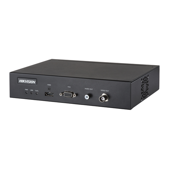
HD Video and Audio Decoder User Manual DS-6900UDI Decoder User Manual Chapter 2 Panels and Connections Front Panel Front panel of DS-6901UDI Figure 2-1 Front Panel of DS-6901UDI Table 2-1 Description of DS-6901UDI Front Panel No. LED Indicator & Interface... - Page 11 HD Video and Audio Decoder User Manual DS-6900UDI Decoder User Manual Table 2-2 Description of DS-6904/6908UDI Front Panel LED Indicator & Interface Connections Power Power indicator HDD1 Hard disk 1 indicator (Reserved) HDD2 Hard disk 2 indicator (Reserved) USB 2.0 interface...
-
Page 12: Rear Panel
HD Video and Audio Decoder User Manual DS-6900UDI Decoder User Manual Table 2-3 Description of DS-6916UDI Front Panel LED Indicator & Interface Connections Table 2-4 HDD1 Hard disk 1 indicator (Reserved) HDD2 Hard disk 2 indicator (Reserved) POWER Power indicator... - Page 13 HD Video and Audio Decoder User Manual DS-6900UDI Decoder User Manual RS-485 serial interface Connect to RS-485 devices, e.g., keyboard. Alarm in 8 alarm inputs Alarm out 8 alarm outputs Power supply 12 VDC power input Rear Panel of DS-6908UDI...
- Page 14 HD Video and Audio Decoder User Manual DS-6900UDI Decoder User Manual Figure 2-6 Rear Panel of DS-6916UDI Table 2-7 Description of DS-6916UDI Rear Panel Interface Connections Wi-Fi For Wi-Fi connection Audio output BNC connector Video output BNC connector HDMI video output...
-
Page 15: Chapter 3 Getting Started
And you can configure the basic network parameters. Activation via Web Browser and Client Software are all supported. For the first-time user, the default user name of DS-6900UDI is admin, and the default IP address is 192.0.0.64. Activating via SADP Software SADP software is used for detecting the online device, activating the camera, and resetting the password. -
Page 16: Activation Via Web Browser
HD Video and Audio Decoder User Manual DS-6900UDI Decoder User Manual STRONG PASSWORD RECOMMENDED–We highly recommend you create a strong password of your own choosing (Using a minimum of 8 characters, including at least three of the following categories: upper case letters, lower case letters, numbers, and special characters.) in order to increase the security of your product. -
Page 17: Activation Via Client Software
HD Video and Audio Decoder User Manual DS-6900UDI Decoder User Manual Figure 3-3 Activation Interface Step 3 Create a password and input the password into the password field. STRONG PASSWORD RECOMMENDED–We highly recommend you create a strong password of your own choosing (Using a minimum of 8 characters, including at least three of the following categories: upper case letters, lower case letters, numbers, and special characters.) in order to... - Page 18 HD Video and Audio Decoder User Manual DS-6900UDI Decoder User Manual Figure 3-4 Control Panel Step 2 Click the Device Management icon to enter the Device Management interface, as shown in the figure below. Figure 3-5 Control Panel Step 3 Check the device status from the device list, and select an inactive device.
- Page 19 HD Video and Audio Decoder User Manual DS-6900UDI Decoder User Manual STRONG PASSWORD RECOMMENDED–We highly recommend you create a strong password of your own choosing (Using a minimum of 8 characters, including at least three of the following categories: upper case letters, lower case letters, numbers, and special characters.) in order to increase the security of your product.
-
Page 20: Chapter 4 Decoder Configuration And Operation By Web Browser
HD Video and Audio Decoder User Manual DS-6900UDI Decoder User Manual Chapter 4 Decoder Configuration and Operation by Web Browser You shall acknowledge that the use of the product with the Internet access might be under network security risks. For avoidance of any network attacks and information leakage, please strengthen your own protection. - Page 21 HD Video and Audio Decoder User Manual DS-6900UDI Decoder User Manual Figure 4-2 Activation Interface STRONG PASSWORD RECOMMENDED–We highly recommend you create a strong password of your own choosing (Using a minimum of 8 characters, including at least three of the following categories: upper case letters, lower case letters, numbers, and special characters.) in order to...
-
Page 22: Decoder Configuration
HD Video and Audio Decoder User Manual DS-6900UDI Decoder User Manual Decoder Configuration 4.1.1 Checking Device Information Purpose You can check the information of the device in the device information interface, such as the Device Type, Device Serial No., Firmware Version, Decoding Version, Web Version, Plugin Version etc. - Page 23 HD Video and Audio Decoder User Manual DS-6900UDI Decoder User Manual Figure 4-5 Configure Time Settings Step 2 Configure the time synchronization by NTP server or manually. Configuring Time Synchronization by NTP Server A Network Time Protocol (NTP) Server can be configured on your device to ensure the accuracy of system date/time.
-
Page 24: Configuring Rs-485/Rs-232 Serial Port
HD Video and Audio Decoder User Manual DS-6900UDI Decoder User Manual Enable the Manual Time Sync. function by selecting the radio button and then click icon to set the system time from the pop-up calendar. Figure 4-7 Configure Time Manually Step 3 Select the time zone that is closest to the device’s location from the drop-down list. -
Page 25: Configuring Basic Network Settings
HD Video and Audio Decoder User Manual DS-6900UDI Decoder User Manual Step 4 Click Save to save the settings. Configure RS-485 Parameters Step 1 Click Configuration > System Settings > RS-485 to enter the following interface: Figure 4-9 Configure RS-485 Settings Step 2 Configure the RS-485 parameters, including the baud rate, data bit, stop bit and parity type. -
Page 26: Configuring Ddns Settings
HD Video and Audio Decoder User Manual DS-6900UDI Decoder User Manual Step 2 Set the network parameters, including the NIC, IP Address, Subnet Mask, Gateway, and DNS Server. The DS-6904/6908/6910/6912/6916UDI provides multiple NICs for selection. Step 3 Click Save to save the settings. - Page 27 HD Video and Audio Decoder User Manual DS-6900UDI Decoder User Manual For the IP Server, you have to apply a static IP, subnet mask, gateway and primary DNS from the ISP. The Server Address should be entered with the static IP address of the PC that runs IP Server software.
-
Page 28: Configuring Wi-Fi Settings
HD Video and Audio Decoder User Manual DS-6900UDI Decoder User Manual If a new alias of the device domain name is defined in the decoder, it will replace the old one registered on the server. 3. Click Save to save the settings. - Page 29 HD Video and Audio Decoder User Manual DS-6900UDI Decoder User Manual Figure 4-15 Wi-Fi Settings Step 2 You can view the Wireless List on the interface. Click Search button to search the available wireless network. The SSID, Security Mode, Signal Strength and Connection Status are shown in the list.
- Page 30 HD Video and Audio Decoder User Manual DS-6900UDI Decoder User Manual WEP 1. For the Authentication type, open and shared are selectable. With the open system authentication, key authentication is not needed for connecting the Wi-Fi. With the shared system authentication, the key must be matched with the preset access point key.
-
Page 31: Configuring Stream Settings
HD Video and Audio Decoder User Manual DS-6900UDI Decoder User Manual 8 to 63 ASCII characters or 8 to 64 hexadecimal characters are allowed. WPA2-Personal Refer to the configuration of WPA-Personal for reference. Step 6 Click Save button to save the settings and the following note window pops up. Click OK to reboot the device and enter the Wi-Fi mode. -
Page 32: Configuring Transparent Channel
HD Video and Audio Decoder User Manual DS-6900UDI Decoder User Manual Figure 4-21 Stream Configuration Interface Step 2 Check the check box of Auto-Switch Stream Type to enable auto switch between main stream and sub-stream. Step 3 Click Save button to save the settings. -
Page 33: Configuring Synchronous Output Settings
HD Video and Audio Decoder User Manual DS-6900UDI Decoder User Manual Figure 4-23 Modifying Interface Step 4 Select the Local Serial Port and the Remote Serial Port to RS-485 or RS-232. Local Serial Port: The serial port used as the transparent channel by the decoder. -
Page 34: Configuring Personalized Settings
HD Video and Audio Decoder User Manual DS-6900UDI Decoder User Manual Figure 4-25 Enable Synchronous Output Step 3 Click OK to confirm the settings. 4.1.10 Configuring Personalized Settings Purpose You can set the stopped decoding image and failed streaming image for the personalized configuration. - Page 35 HD Video and Audio Decoder User Manual DS-6900UDI Decoder User Manual Figure 4-27 Configure User Account Step 2 You can add, modify or delete the user account, as well as configure operating permissions for each user account. Figure 4-28 Add User Account and Set Permissions...
-
Page 36: Importing/Exporting Configuration Files
HD Video and Audio Decoder User Manual DS-6900UDI Decoder User Manual Up to 32 user accounts can be added including the admin. For the admin user, only the password can be modified. You must input the admin password if you want to modify the user account except the admin. -
Page 37: Rebooting The Device
HD Video and Audio Decoder User Manual DS-6900UDI Decoder User Manual Figure 4-30 Upgrade the Device When logging in to the device for the first time, install the plug-in according to the prompt on the screen. The device will restart after completing the upgrade. -
Page 38: Setting Video Wall Layout
HD Video and Audio Decoder User Manual DS-6900UDI Decoder User Manual Setting Video Wall Layout Purpose To realize the display of the decoded video on the video wall, you must set the Video Wall Configuration first so as to link the video output with video wall. -
Page 39: Configuring Decoding Output
HD Video and Audio Decoder User Manual DS-6900UDI Decoder User Manual Figure 4-35 Close the Window Configuring Decoding Output Purpose In the output list, there are two kinds of video output signals, respectively BNC and HDMI. You can configure the resolution and output mode. - Page 40 HD Video and Audio Decoder User Manual DS-6900UDI Decoder User Manual Figure 4-38 Batch Configuration Step 5 Click OK to save the settings. Configuring HDMI Output Step 1 Right click one of the HDMI signal sources. Figure 4-39 HDMI Decoding Output Step 2 Click Resolution Configuration to enter the interface below.
- Page 41 HD Video and Audio Decoder User Manual DS-6900UDI Decoder User Manual Figure 4-41 Set LCD Resolution LED 1. Select the Output Mode to LED. 1. Input the LED Width and LED Height in the corresponding text fields. Figure 4-42 Set LED Resolution ...
-
Page 42: Decoding Operation
HD Video and Audio Decoder User Manual DS-6900UDI Decoder User Manual Figure 4-43 Batch Configuration Step 5 Click OK to save the settings. Step 6 Right click one of the HDMI signal sources and click Output Mode Configuration to pop up the interface below. -
Page 43: Adding An Encoding Device
HD Video and Audio Decoder User Manual DS-6900UDI Decoder User Manual Figure 4-45 Video Wall Interface Refer to the following figure for the video wall description. Table 4-1 Description of Video Wall Description Encoding Device List: The encoding devices added in the Web Scene: The Web supports up to 8 scenes by default, capable of independent scene configuration and fast switching. - Page 44 HD Video and Audio Decoder User Manual DS-6900UDI Decoder User Manual Adding an Encoding Device via IP Address Step 1 Click IP to add encoding devices. Figure 4-46 Encoding Device List Step 2 Input Device Name, IP Address, Port, User Name, Password and Channel Number and select the Transmission Protocol, Area Name, and Device Manufacturer.
- Page 45 HD Video and Audio Decoder User Manual DS-6900UDI Decoder User Manual Step 3 (Optional) You can also click to add a new area and click to save the area. Step 4 Click Next to select the channel. The channel(s) displayed here depend(s) on the Channel Number you input on the previous page.
-
Page 46: Modifying The Area And Added Encoding Device
HD Video and Audio Decoder User Manual DS-6900UDI Decoder User Manual Step 2 Input the Device Name and URL. Select the Area Name from the dropdown list or click add a new area. Figure 4-50 Add Device via URL Step 3 Click OK to save the settings. -
Page 47: Deleting The Area Or Added Encoding Device
HD Video and Audio Decoder User Manual DS-6900UDI Decoder User Manual Figure 4-52 Modify Encoding Device Step 2 Click OK to save the new settings. 4.4.3 Deleting the Area or Added Encoding Device Step 1 Select one area or one encoding device and click Delete to pop up the note interface below. - Page 48 HD Video and Audio Decoder User Manual DS-6900UDI Decoder User Manual Dragging the Channel to the Video Wall Step 1 Drag the channel from the left side list to realize the decoding in the selected window. You can also drag an area file to the video wall to decode the added encoding devices in the area file on the video wall.
- Page 49 HD Video and Audio Decoder User Manual DS-6900UDI Decoder User Manual Figure 4-56 Decoding Channel Interface Stop Decoding Click the button to stop decoding. Decoding Status 1. Click the button to enter the decoding status interface. 2. View the decoding status.
- Page 50 HD Video and Audio Decoder User Manual DS-6900UDI Decoder User Manual Figure 4-59 Turn on Audio 2. Select from the dropdown list to enable the audio in the corresponding window. 3. Click OK to save the settings. Decoding Delay 1.
-
Page 51: Switching Encoding Channel
HD Video and Audio Decoder User Manual DS-6900UDI Decoder User Manual Step 2 Click Open Window via Coordinate to enter the interface below. Figure 4-62 Open Window via Coordinate Step 3 Input the Left Margin, Right Margin, Width and Height in the corresponding text fields. -
Page 52: Window Roaming
HD Video and Audio Decoder User Manual DS-6900UDI Decoder User Manual Figure 4-65 Start Auto-Switch Step 3 Click OK to save the settings. 4.4.7 Window Roaming Step 1 Drag one camera from the left side list to the video wall layout to enable decoding in the corresponding window automatically. - Page 53 HD Video and Audio Decoder User Manual DS-6900UDI Decoder User Manual Step 1 In the Video Wall interface drag the channel from the left side list to realize the decoding in the selected window. Figure 4-67 Save the Scene Step 2 Click Save to save the scene directly or click Save as to pop up the following dialog box.
-
Page 54: Chapter 5 Decoder Configuration And Operation By Client Software
HD Video and Audio Decoder User Manual DS-6900UDI Decoder User Manual Chapter 5 Decoder Configuration and Operation by Client Software Run the disk of iVMS-4200 Video Wall Client Software, and double click the icon to install it in your PC. In this chapter, the basic procedure of operating the decoder by the software is described and the description is based on the video wall client software version shown in the following figure. -
Page 55: Adding An Encoding/Decoding Device
HD Video and Audio Decoder User Manual DS-6900UDI Decoder User Manual Table 5-1 Decoding Toolbar Icon Name Description Start/Stop Live View Start/Stop live view of all the windows. Start/Stop decoding all signal sources and Start/Stop All Decoding cameras. Close all the windows displayed on the Close All Windows video wall. - Page 56 HD Video and Audio Decoder User Manual DS-6900UDI Decoder User Manual Figure 5-3 Device Management Interface Step 2 Click Add Device and you can add device manually by means of IP address/domain, IP segment and HiDDNS. Figure 5-4 Add Device by IP/Domain Step 3 You can add device by detecting the online devices.
-
Page 57: Configuring Video Wall Settings
HD Video and Audio Decoder User Manual DS-6900UDI Decoder User Manual Figure 5-6 List of Added Devices Configuring Video Wall Settings 5.2.1 Configuring Video Wall Layout Adding a Video Wall Step 1 Click Video Wall tab to enter the Video Wall interface. - Page 58 HD Video and Audio Decoder User Manual DS-6900UDI Decoder User Manual Figure 5-8 Add Video Wall Step 3 Input the Video Wall Name, and the number of windows in row and column text fields. Step 4 Click Add to add the video wall.
-
Page 59: Configuring Decoding Output
HD Video and Audio Decoder User Manual DS-6900UDI Decoder User Manual Modifying a Video Wall Click Modify Video Wall to edit current video wall’s layout, name and decoding outputs. Figure 5-10 Modify Video Wall Deleting a Video Wall Select Delete Video Wall and the information dialog box pops up. Click OK to delete the selected video wall. - Page 60 HD Video and Audio Decoder User Manual DS-6900UDI Decoder User Manual Figure 5-12 Edit BNC Output Step 2 Select the Output Type and set the corresponding parameters. Only LCD output type can be configured. Step 3 Select the Video Standard. PAL and NTSC are selectable.
- Page 61 HD Video and Audio Decoder User Manual DS-6900UDI Decoder User Manual Figure 5-14 Edit HDMI Output Step 2 Select the Output Type and set the corresponding parameters. You can select LCD and LED. LCD 1. Select the Output Type to LCD.
-
Page 62: Configuring General Parameters Of Video Wall
HD Video and Audio Decoder User Manual DS-6900UDI Decoder User Manual Figure 5-16 Batch Configuration Step 4 Click OK to save the settings. You can also modify the LED resolution by selecting the LED area and click LED Resolution Config to input the LED Resolution in the text fields. -
Page 63: Configuring Virtual Screen
HD Video and Audio Decoder User Manual DS-6900UDI Decoder User Manual Step 3 Select Blank Screen or Last Frame when decoding ends. If you select Blank Screen, the screen will change blank when the decoding ends. If you select Last Frame, the screen will show the last frame when the decoding ends. - Page 64 HD Video and Audio Decoder User Manual DS-6900UDI Decoder User Manual Figure 5-20 Configure Virtual Screen Step 4 Select the window(s) you want to add virtual screen. You cannot add virtual screen across the LCD and LED areas. Step 5 Click Add Virtual Screen to enter Configure Virtual Screen interface.
-
Page 65: Displaying Video On Video Wall
HD Video and Audio Decoder User Manual DS-6900UDI Decoder User Manual 3. Click OK to save the settings and the dotted line in grey constitutes the virtual screen division. Figure 5-22 Added Virtual Screen Step 6 (Optional) Select the configured virtual screen area and click Delete Virtual Screen to delete... -
Page 66: Decoding And Displaying Video
HD Video and Audio Decoder User Manual DS-6900UDI Decoder User Manual After enabling decoding and displaying, the video from the encoding devices can be displayed on the video wall. And the real-time live view is shown on the physical video wall. - Page 67 HD Video and Audio Decoder User Manual DS-6900UDI Decoder User Manual You can click on the lower part of the interface to stop decoding of all the windows. Step 4 If the decoded camera supports PTZ control, you can click PTZ Control to expand the PTZ control panel.
-
Page 68: Opening Window Via Coordinate
HD Video and Audio Decoder User Manual DS-6900UDI Decoder User Manual Decoding Status: View the status of the decoding channel, like decoding status and stream type. Stick at Bottom: Generally the selected window is at top by default. Click Stick at Bottom to place the selected window at bottom. -
Page 69: Configuring Playback
HD Video and Audio Decoder User Manual DS-6900UDI Decoder User Manual Figure 5-29 Open the Window via Coordinate (2) Step 2 Select the Device Name from the drop down list, and input the X-Coordinate, Y-Coordinate, Width and Height. Step 3 Click OK to save the settings and the opened window will be displayed on the video wall. - Page 70 HD Video and Audio Decoder User Manual DS-6900UDI Decoder User Manual Figure 5-30 Video Wall Step 2 Click Window at the bottom to unfold more configuration and operation toolbar. Step 3 Click Start Playback to start searching the video files of the camera.
-
Page 71: Configuring Auto-Switch Decoding
HD Video and Audio Decoder User Manual DS-6900UDI Decoder User Manual Table 5-2 Playback Toolbar Icon Function Pause/Start the playback Delete View Slow Forward Fast Forward Start/Stop Clipping Capture 5.3.4 Configuring Auto-Switch Decoding Purpose Auto-switch decoding refers to you can configure multiple video streams in a video output and the dwell time in switching video streams. -
Page 72: Decoding Thermal Network Camera
HD Video and Audio Decoder User Manual DS-6900UDI Decoder User Manual Step 2 Click Window Configuration to pop up the configuration dialog box. Figure 5-34 Window Configuration Step 3 Configure the parameters as needed. The window status shows the current status of the selected window. - Page 73 HD Video and Audio Decoder User Manual DS-6900UDI Decoder User Manual 1. Log in to the camera via the Web browser. 2. Click Configuration > Advanced Configuration > System > VCA Resource Type to enter the VCA Resource Type configuration interface.
- Page 74 HD Video and Audio Decoder User Manual DS-6900UDI Decoder User Manual Figure 5-36 Temperature Measurement and Alarm 2. Set the alarm rule: Select a temperature measurement rule from the rule list and configure the parameters. Name: You can customize the rule name.
- Page 75 HD Video and Audio Decoder User Manual DS-6900UDI Decoder User Manual Tolerance Temperature: Set the tolerance temperature and the device judges whether the triggered alarm stops until the device temperature/temperature difference is lower than rule temperature by tolerance temperature. For example, set tolerance temperature as 3°C, set alarm temperature as 55°C, and set pre-alarm temperature as...
- Page 76 HD Video and Audio Decoder User Manual DS-6900UDI Decoder User Manual 5. Set Temperature Difference Alarm. Click Temperature Difference Alarm to enter the temperature difference alarm interface, up to four temperature difference alarms can be set. Temperature Difference Alarm is only applicable to the targets set by frame.
- Page 77 HD Video and Audio Decoder User Manual DS-6900UDI Decoder User Manual Figure 5-41 Live View Configuring Dynamic Fire Source Detection Step 1 Configure the VCA resource type. 1. Log in to the camera via the Web browser. 2. Click Configuration > Advanced Configuration > System > VCA Resource Type to enter the VCA Resource Type configuration interface.
- Page 78 HD Video and Audio Decoder User Manual DS-6900UDI Decoder User Manual 2. Check the checkbox of Enable Dynamic Fire Source Detection to enable the function. 3. (Optional) Check the checkbox of Display Fire Source Frame on Stream to display a red frame around the fire source on stream when fire occurs.
- Page 79 HD Video and Audio Decoder User Manual DS-6900UDI Decoder User Manual Step 3 Check the checkbox of Enable Ship Detection to enable the function. Step 4 Check the checkbox of Display Detection Frame on Video to display the frame and alarm line on stream.
-
Page 80: Decoding Thermal Network Camera On The Video Wall
HD Video and Audio Decoder User Manual DS-6900UDI Decoder User Manual 2. On the Live View Parameters section, select the Enable radio button after Rules to display the colored marks when the motion detection, face detection, or intrusion detection is triggered. -
Page 81: Remote Screen Control
HD Video and Audio Decoder User Manual DS-6900UDI Decoder User Manual Figure 5-46 Decode Thermal Camera on the Video Wall If VCA is enabled for the thermal network camera, the decoder can analyze the VCA behavior, mark the moving target and track it. You can view the VCA information marked in the green frames in the live view. -
Page 82: Configuring The Rsc Server
HD Video and Audio Decoder User Manual DS-6900UDI Decoder User Manual 5.5.1 Configuring the RSC Server Step 1 Install the RSE Server, which enables the PC screen to be displayed on the video wall, and double-click to run it. Figure 5-47... -
Page 83: Remote Screen Control Via Rsc Server
HD Video and Audio Decoder User Manual DS-6900UDI Decoder User Manual 5.5.2 Remote Screen Control via RSC Server Step 1 Enter the Video Wall interface and click in the Camera list area, or click Device Management interface to add the RSC server. - Page 84 HD Video and Audio Decoder User Manual DS-6900UDI Decoder User Manual Figure 5-51 Link RSC to Video Wall Step 5 Right click on the window and select Screen Control to remotely control the signal source. The RSC server supports the screen control for 1-channel video output only.
- Page 85 HD Video and Audio Decoder User Manual DS-6900UDI Decoder User Manual Figure 5-53 Screen Control Interface Click to display all the image files in the directory set in the RSC Sever. Figure 5-54 Screen Control Interface (1) Click to display all the video files in the directory set in the RSC Sever.
-
Page 86: Remote Configuration
HD Video and Audio Decoder User Manual DS-6900UDI Decoder User Manual Figure 5-56 Screen Control Interface (3) Click to pop up the following remark tool bar. You can select a color and set the line width to make remarks on the PPT. -
Page 87: Configuring Port Aggregation
HD Video and Audio Decoder User Manual DS-6900UDI Decoder User Manual Step 2 Configure the System parameters, Network parameters and Event parameters on the Remote Configuration interface. 5.6.1 Configuring Port Aggregation Purpose The Port Aggregation (Ethernet Channel) is port link aggregation technology or port-channel architecture used for the connection between the switches. -
Page 88: Configuring Wi-Fi Settings
DS-6900UDI Decoder User Manual The port aggregation is not supported by DS-6901UDI. The switch connected to DS-6900UDI must be configured with the port aggregation as well. Two adjacent network interfaces cannot be selected to form a link. For example, you can select Network Interface 1 and Network Interface 3, or Network Interface 2 and Network Interface 4. - Page 89 HD Video and Audio Decoder User Manual DS-6900UDI Decoder User Manual Step 2 Check the checkbox of Enable to enable Wi-Fi. Step 3 Input an effective SSID. Step 4 Click WLAN Settings tab to enter the WLAN Settings interface. Figure 5-61...
- Page 90 HD Video and Audio Decoder User Manual DS-6900UDI Decoder User Manual Step 7 Select one Key for activation. 4 keys can be selected. Input the key and you can check the checkbox of Display Password to show the clear-text password.
-
Page 91: Chapter 6 Display Via Wi-Fi Connection
Chapter 6 Display via Wi-Fi Connection Purpose With the Wi-Fi module connected, the DS-6900UDI supports displaying the signal from mobile phone or pad via AirPlay (IOS) or DLNA (Android) to the video wall or other display units. Step 1 Insert the Wi-Fi module to the DVI video input connector on the rear panel of the device. -
Page 92: Chapter 7 Appendix
HD Video and Audio Decoder User Manual DS-6900UDI Decoder User Manual Chapter 7 Appendix Specifications Table 7-1 DS-6901/6904/6908 UDI Specification Model DS-6901UDI DS-6904UDI DS-6908UDI WSXGA: 1680×1050@60Hz WXGA: 1440×900@60Hz WXGA:1280×800@60Hz, 1366×768@60Hz, 1080p: 1920 × 1080@50/60Hz Video/Audio DVI-I output input UXGA: 1600 × 1200@60Hz XVGA: 1280 ×... - Page 93 HD Video and Audio Decoder User Manual DS-6900UDI Decoder User Manual 12MP@20fps:8-ch 12MP@20fps: 2- 8MP@30fps: 12MP@20fps:4-ch 8MP@30fps: 4-ch 8MP@30fps: 8-ch 5MP@30fps: Decoding 5MP@30fps: 6-ch 5MP@30fps: 12-ch capability 3MP@30fps: 10- 3MP@30fps: 20-ch 3MP@30fps: 1080p@30fps: 32- 1080p@30fps: 16- 1080p@30fps: 64- 1/4/6/8/9/12/16/2 1/4/6/8/9/12/16/...
- Page 94 HD Video and Audio Decoder User Manual DS-6900UDI Decoder User Manual Table 7-2 DS-6910/6912/6916 UDI Specification Model DS-6910UDI DS-6912UDI DS-6916UDI WSXGA: 1680×1050@60Hz WXGA: 1440×900@60Hz WXGA: 1280×800@60Hz, 1366×768@60Hz, 1080p: 1920 × 1080@50/60Hz Video/ DVI-I UXGA: 1600 × 1200@60Hz Audio input output XVGA: 1280 ×...
- Page 95 HD Video and Audio Decoder User Manual DS-6900UDI Decoder User Manual 2; 10/100/1000 Mbps self-adaptive management network interface Network interface 2; 10/100/1000 Mbps self-adaptive Ethernet interface 16; 10M/100 Mbps self-adaptive Ethernet interface Serial interface 1 RS-232 (RJ 45), 1 RS-485...
-
Page 96: Faq
HD Video and Audio Decoder User Manual DS-6900UDI Decoder User Manual Why cannot ping the decoder? − Check the cable and the switch. − Please refer to Chapter 3 to configure the IP address of the decoder. Why cannot connect the decoder with client software? −... -
Page 97: List Of Third-Party Ip Cameras Access
HD Video and Audio Decoder User Manual DS-6900UDI Decoder User Manual List of Third-Party IP Cameras Access IP Camera Supported Video Model Manufacturer Format SP306H Panasonic SP336H SNC-CH220 Sony SNC-RH124 P5532 Axis Q7404 H.265+. H.265, H.264, Sanyo VCC-HD2500P H.264+, MJPEG, MPEG4,... - Page 98 HD Video and Audio Decoder User Manual DS-6900UDI Decoder User Manual...
Need help?
Do you have a question about the DS-6900UDI and is the answer not in the manual?
Questions and answers