
Related Manuals for Windsor Armada BRC 40/22 120V


Summary of Contents for Windsor Armada BRC 40/22 120V
- Page 1 Armada BRC 40/22 120V Carpet Extractor Operating Instructions (ENG) MODELS: BRC 40/22 1.008-060.0 86409500-E 02/01/17...
-
Page 2: Machine Data Label
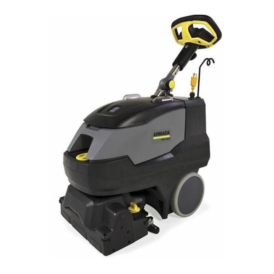
Machine Data Label Overview This carpet extractor is an electrical powered, portable carpet extractor intended for commercial use. The appliance sprays a cleaning solution onto the carpet, agitates the wet carpet, and then extracts the soiled solution back into the unit's recovery tank. The appliance is available with an optional hand tool for cleaning upholstery and stairs. Karcher North America Headquarters 4555 Airport Way Denver, CO 80239... -
Page 3: Table Of Contents
Table of Contents Machine Data Label ......2 Overview ........2 Table of Contents . -
Page 4: How To Use This Manual
How To Use This Manual This manual contains the following sections: The SAFETY section contains important information regarding hazardous or unsafe practices of the • How to Use This Manual machine. Levels of hazards are identified that could • Safety result in product damage, personal injury, or severe •... -
Page 5: Safety
Safety Safety Labels NOTE: These drawings indicate the location of safety labels on the machine. If at any time the labels become illeg- ible, promptly replace them. EMPLACEMENT DE L'ÉTIQUETTE DE SÉCURITÉ REMARQUE : Ces dessins indiquent l'emplacement des étiquettes de sécurité sur la machine. Si, à tout moment, les étiquettes deviennent illisibles, contactez votre représentant autorisé... -
Page 6: Important Safety Instructions
Safety IMPORTANT SAFETY INSTRUCTIONS When using this machine, basic precaution must always be followed, including the following: READ ALL INSTRUCTIONS BEFORE USING THIS MACHINE. To reduce the risk of fire, electric shock, or injury: Connect to a properly grounded outlet. See Grounding Instructions. Do not leave the machine unattended. -
Page 7: Consignes De Sécurité Importantes
Safety CONSIGNES DE SÉCURITÉ IMPORTANTES Lors de l'utilisation de cette machine, des précautions de base doivent toujours être prises, y compris les précautions suivantes : LIRE TOUTES LES INSTRUCTIONS AVANT D'UTILISER CETTE MACHINE. Pour réduire le risque d'incendie, d'électrocution ou de blessure : Cet appareil ne doit être connecter qu a des prises ayant une sortie de terre. -
Page 8: Hazard Intensity Level
Safety The following symbols are used throughout this guide as indicated in their descriptions: HAZARD INTENSITY LEVEL There are three levels of hazard intensity identified by signal words -WARNING and CAUTION and FOR SAFETY. The level of hazard intensity is determined by the following definitions: WARNING - Hazards or unsafe practices which COULD result in severe personal injury or death. -
Page 9: Niveau D'intensité Du Danger
Safety Les symboles suivants sont utilisés dans tout ce manuel, tels que décrits ici : NIVEAU D'INTENSITÉ DU DANGER Il existe trois niveaux d'intensité du danger, identifiés par des termes d'avertissement - AVERTISSEMENT, ATTENTION et POUR VOTRE SÉCURITÉ. Le niveau d'intensité du danger est déterminé par les définitions suivantes : AVERTISSEMENT - Les dangers ou des pratiques contraires à... -
Page 10: Grounding Instructions
Safety Grounding Instructions 120 Volt Models: THIS PRODUCT IS FOR COMMERCIAL This appliance is for use on a nominal 120-volt circuit, and has a grounded plug that looks like the plug in "Fig. USE ONLY. A". A temporary adapter that looks like the adapter in Electrical: "Fig. -
Page 11: Operations
Interim Carpet Maintainer in conjunction with The function of the operator control system is to allow Windsor Red Carpet Encapsulating Interim Cleaning the operator to select the desired function to perform. (W450-4) or Encapsulating Interim Cleaning with... -
Page 12: Technical Specification
Operations Technical Specification ITEM MEASURE Height 44 inches (1118 mm) Length 35 inches (889 mm) Width 18.5 inches (470 mm) Width of scrub path 16 inches (406 mm) This appliance is not intended for use by persons (including children) with reduced physical, sensory or mental capabilities, or lack of experience and knowledge, unless they have been given supervision or instruction concerning use of the appliance by a person responsible for their safety. -
Page 13: Technical Specifications
Operations Technical Specifications ITEM DIMENSION/CAPACITY Construction Plastic Injection-molded chassis with rotationally molded polyethylene tank Three stage, bypass, 1.5 hp (1,119 watts), 100 cfm (2.8m³/min), 120" (3050 Vacuum Motor mm) waterlift 50 psi (3.5 bar) - Interim Solution Pump 100 psi (7 bar) - Restorative Brush Motor .53 hp (400 watts) DC Brush... -
Page 14: Controls
Operations Controls Display The LED lights in the center are (from left to right): 1. Power 2. Vacuum 3. Brush 4. Solution 5. Eco! Mode. The switch on the left controls the solution flow. The Reverse Solution Switch switch on the right allows the operator to reverse the brush motor, effectively moving the machine in an opposite direction. -
Page 15: Rear Cover Storage
Operations Display 1. Power Light • Green indicates that the machine has power. • Off indicates the machine does not have power or rotary switch is set to the off position. • See Trouble Shooting section if Green light is not on when it should be. 2. -
Page 16: Components
Operations Components 1. Operator Controls and Display 8. Dirty Water Clear Observation Cover 2. Recovery Lid 9. Recovery Drain Hose 3. Recovery Tank 10. Control Height Adjustment - Operator Controls 4. Scrub Deck 11. Deep Extraction Jets 5. Solution Fill Cover 12. -
Page 17: Pre Run Setup
Operations Pre Run Setup 1. To unfold handle, loosen knob, rotate upper steering column and steering wheel back to stop. OPERATION STORAGE Tighten knob. STEP 1 2. Install the vacuum shoe and brush. Fill solution tank with water and chemical. (see Filling the Solution Tank instructions). -
Page 18: Filling The Solution Tank
Operations Filling The Solution Tank Do not put defoamer or solvent chemicals in the REMOVE SOLUTION solution tank. FILL COVER Do not allow water to spill into vacuum motor inlet. Dry spills from top of solution tank. Do not tip machine on back when full as water may spill from machine. -
Page 19: Operating The Machine
Operations Operating The Machine • Rotate the brush height adjustment knob to position “1” which is the highest brush position. Roll the machine forward to lower the machine Expected Run Time off the kickstand. The expected run time for this machine depends upon •... -
Page 20: Operating The Machine
Operations Operating The Machine 3. Turn on Solution Switch. • Press the bottom of the switch to turn solution • Press the top of the switch to turn solution off. STEP 3 4. Squeeze the large Yellow Trigger Switch to make the machine move, run the brush and dispense solution. - Page 21 Operations 6. During operation, observe the following: VACUUM INTAKE This machine is equipped with clear dome to facili- tate operator viewing of dirty solution and vacuum SOLUTION INTAKE air flow. During operation, observe the vacuum intake: Any amount of water or foam entering the vacuum system can damage the vacuum motor.
-
Page 22: To Clean Under Desks Or Dead End Hallways
Operations To Clean Under Desks Or Dead End 10. Place the tank back onto the base machine by putting the front in first and then lowering the back Hallways into place. Install the recovery drain cap and hang By activating the momentary reverse switch, the brush back into place. -
Page 23: Accessory Tool Connection And Use
Operations Accessory Tool Connection and Use NOTE: Use only manufacturer supplied accessory tools. See Optional Accessories section. ° 1. Spin the deck 180 so that the vacuum shoe is at HAND TOOL HAND TOOL the front of the machine. VACUUM HOSE 2. - Page 24 Notes 86409500 Operator’s Manual - Armada BRC 40/22...
-
Page 25: Maintenance
Maintenance Service Schedule MAINTENANCE DAILY WEEKLY QUARTERLY Check machine for cord damage Check recovery dome and gasket for damage and cleanliness Check brushes - should be clean with no lint or strings attached Clean debris tray behind brush Clean the underside of the brush deck area Observe spray pattern Inspect vac shoe for blockage;... -
Page 26: Components
Maintenance Components 1. Brush 6. Solution Strainer 2. Deep Extraction Jets 7. Spray Jet - Interim 3. Debris Tray 8. Vacuum Shoe 4. Float Shut-off 9. Height Adjust Wheels 5. Solution Drain Hose solution pressure loss. If the cable insulation is broken Periodic Maintenance or frayed, repair or replace it immediately. -
Page 27: Vacuum Shoe Cleaning
Maintenance 6. Remove lint and dirt build-up from brush and Vacuum Shoe Cleaning housing. 1. Unplug the power cord and move the machine to a 7. Check float and shut-off screen and clean as safe level area. necessary. 2. To remove the vacuum shoe assembly, spin the 8. -
Page 28: Scrub Deck
Maintenance Scrub Deck 1. Scrub Brush Motor 2. Scrub Brush 3. Brush Height Adjustment 4. Vacuum Motor 5. Solution Pump Only qualified maintenance personnel are to perform the following repairs. Seul le personnel d'entretien qualifié peut effectuer des réparations. 86409500 Operator’s Manual - Armada BRC 40/22... -
Page 29: Scrub Head Maintenance
Maintenance Scrub Head Maintenance Scrub Brush Replacement The cylindrical scrub head is designed to scrub chemicals into the carpet and propel the machine. Only use the brush provided with the appliance or those specified in the instructions manual. The use The Scrub brush should be replaced when the brush is of other brushes may impair safety. -
Page 30: Circuit Protection
Maintenance Circuit Protection Circuit breakers interrupt the flow of power in the event of an electrical overload. When a circuit breaker is tripped, reset it by pressing the button. If a circuit breaker continues to trip, contact your service representative. Circuit Breaker 86409500 Operator’s Manual - Armada BRC 40/22... -
Page 31: Troubleshooting
Maintenance Troubleshooting PROBLEM CAUSE SOLUTION Cord is not plugged in Plug in cord. No power, nothing runs, no Circuit breaker tripped on machine. Reset breaker. green light on power icon with Circuit breaker tripped in building. Reset breaker. switch on. Faulty switch. - Page 32 Maintenance Troubleshooting PROBLEM CAUSE SOLUTION Allow brush motor to cool and reduce brush Machine stops working and motor load by adjusting deck height to Brush motor is overheating brush light blinks red 5 times lower number setting with deck height knob.
-
Page 33: Suggested Spare Parts
Suggested Spare Parts 86402850 GASKET, LID 86409460 STRAINER 86004570 JET BODY (3) 86012550 JET PROMAX 86411180 ROLLER BRUSH 86412780 JET MINI PROMAX (2) 86403040 SOLUTION HOSE 86402570 RECOVERY DRAIN HOSE 86003630 FLOAT SHUT-OFF 86414120 VACUUM MOTOR 86405260 PUMP 86409500 Operator’s Manual - Armada BRC 40/22...
Need help?
Do you have a question about the Armada BRC 40/22 120V and is the answer not in the manual?
Questions and answers