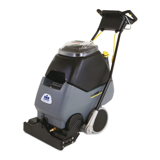
Windsor Clipper CLP12 Operating Instructions Manual
Carpet extractor
Hide thumbs
Also See for Clipper CLP12:
- Operator instructions manual (42 pages) ,
- Operating instructions manual (31 pages)

Subscribe to Our Youtube Channel
Related Manuals for Windsor Clipper CLP12


Summary of Contents for Windsor Clipper CLP12
- Page 1 CARPET EXTRACTOR Operating Instructions MODEL: CLP12 Read these instructions before operating the machine 98630 08/19/03...
-
Page 2: Table Of Contents
TABLE OF CONTENTS MODEL DATE OF PURCHASE SERIAL NUMBER SALES REPRESENTATIVE # DEALER NAME Data Log/Table of Contents....1 Maintenance ........16-18 Safety Instructions ......2 Technical Specifications....19 Grounding Instructions .....3 Service Schedule......20 Controls..........4-6 Parts Lists ........21-34 Operations........7-13 Spare Parts/Notes...... -
Page 3: Safety Instructions
SAFETY INSTRUCTIONS IMPORTANT SAFETY INSTRUCTIONS When using an electrical appliance, basic precaution must always be followed, including the following: READ ALL INSTRUCTIONS BEFORE USING THIS MACHINE. This machine is for commercial use. WARNING: To reduce the risk of fire, electric shock, or injury: Connect to a properly grounded outlet. -
Page 4: Grounding Instructions
GROUNDING INSTRUCTIONS THIS PRODUCT IS FOR COMMERCIAL USE ONLY. PROPER GROUNDING ELECTRICAL: Grounding Pin Metal Screw In the USA this machine operates on a standard 15 amp 115V, 60 hz, A.C. power circuit . The amp, hertz, and voltage are listed on the data label found Grounded Adaptor on each machine. - Page 5 CONTROLS/COMPONENT LOCATIONS Main Handle. Used to pull and maneuver machine. Handle Adjustment. Used to adjust height of handle, and allow machine to be used in “PUSH” or “PULL orientation. Electrical Cord. Solution Switch. Turns on pump. Continuous position (bottom) activates electro-valve to dispense solution to floor through jets.
- Page 6 CONTROLS/COMPONENT LOCATIONS Solution Accessory Tool Hookup. Used for various auxiliary cleaning tools. Vacuum Hose Door. Used to connect various auxiliary 1 ½ inch cleaning tool vacuum hoses. Brush Height Adjustment. Used to regulate brush height from storage position to various carpet heights.
-
Page 7: Controls
CONTROLS/COMPONENT LOCATIONS Solution Intake Cover. Vacuum Intake Cover. Float Shut-Off. Clean-Out Opening. Pour Spout. Lift Handle. CLIPPER 98630 12/14/98... - Page 8 FILLING OPERATIONS STEP RECOVERY TANK Remove solution tank lid SOLUTION TANK STEP Add water 12 gal. (45.5 ltr.) 140°F (60°C) FILL LINE STEP 12 – 24oz. FILLING THE CLIPPER (356ml – 711ml) NOTE: Use clean bucket of water to fill solution tank Add cleaning Do not put defoamer, solvents, spotter or chemical...
-
Page 9: Operations
OPERATIONS STEP Remove electrical cord and literature from recovery tank. Fill solution tank (see filling instructions page 7). STEP Plug cord into grounded outlet. Note: Be sure dome is seated on recovery tank, and float shut-off is installed correctly. STEP Adjust brush to proper setting. - Page 10 OPERATIONS STEP Adjust handle to comfortable operating position. Tip machine back by main handle to move to starting point. Lower machine to floor. STEP STEP Select continuous setting to start solution spray or select intermittent setting to enable use of trigger switches to start solution spray.
-
Page 11: Cleaning Procedure
CLEANING PROCEDURE 1. This machine can be operated in either direction. For smaller areas operate the machine by pulling rearward. 2. For larger unobstructed areas, flip the handle and use the machine’s brush assisted propelling motion. Start at wall closest to power outlet. STEP For small areas, pull straight back without pushing down on handle. - Page 12 CLEANING PROCEDURE Start at wall closest to power outlet. For large areas flip handle and operate STEP machine in parallel passes, overlapping brush path. Clean perimeter last. During operation, observe the following: The Clipper is equipped with STEP SOLUTION clear internal covers to facilitate INTAKE COVER operator viewing of dirty solution and vacuum air flow.
- Page 13 CLEANING PROCEDURE To speed drying, use a STEP Windblower fan. Empty recovery tank by releasing STEP dump hose. Use a hose with cold water to clean out the recovery tank. Also drain solution tank after each use. RECOVERY DRAIN SOLUTION DRAIN CLIPPER 98630 12/14/98...
- Page 14 ACCESSORY TOOL USAGE STEP Use only one of the following acceptable accessory tools. CST DDH DH DHT UPH-3 SW-PRO SFW 39504 Pull back collar and insert over machine mounted fitting, then release collar to lock into place. Lift door on front of vacuum shoe STEP and insert 1 ½...
-
Page 15: Troubleshooting
TROUBLESHOOTING CHART PROBLEM CAUSE SOLUTION 1. Is the cord plugged in. 1. Plug in cord. No Power, Nothing Runs 2. Circuit breaker tripped in building. 2. Reset breaker 3. Faulty switch. 3. Call for service. 4. Faulty power cord or pigtail. 4. -
Page 16: Wiring Diagram
WIRING DIAGRAM CLIPPER 98630 10/19/02... -
Page 17: Maintenance
MAINTENANCE PERIODIC MAINTENANCE 8. Check cooling air screen (located on frame behind left wheel) for lint or debris. Twice a month, flush a white vinegar solution 9. Check float and shut-off screen and clean (One quart vinegar to two gallons of water) or as necessary. -
Page 18: Belt Replacement
MAINTENANCE ONLY QUALIFIED Vac Motor Carbon Brushes Replacement WARNING: MAINTENANCE End Cap PERSONNEL ARE TO PERFORM THE FOLLOWING REPAIRS. WARNING: The green Carbon Brushes ground wire must be VACUUM MOTOR REPLACEMENT 115V attached for safe 1. Turn off all switches and unplug machine. operation. - Page 19 MAINTENANCE ONLY QUALIFIED MAINTENANCE PERSONNEL ARE TO PERFORM WARNING: THE FOLLOWING REPAIRS. SOLUTION PUMP REPLACEMENT 1. Turn off all switches and unplug the machine. 2. Remove recovery tank. 3. Remove the (2) screws that fasten the solution tank to the frame, and tilt tank back to expose the inside of the frame.
-
Page 20: Technical Specifications
TECHNICAL SPECIFICATIONS POWER TYPE GENERAL DIMENSIONS/WEIGHT ELECTRICAL: 115 V, 15 A, 60 HZ Vacuum shoe: 20” (51 cm) cast aluminum with spring loaded down ELECTRIC VACUUM MOTOR: (1) –3 stage, 1 hp, 99 pressure cfm (2.80 cubic meters/min.) Waterlift –117” (297cm) WHEELS: (2) 10”... -
Page 21: Service Schedule
MAINTENANCE SERVICE SCHEDULE MAINTENANCE DAILY WEEKLY QUARTERLY Check machine for cord damage Check recovery dome and gasket for damage and cleanliness Check brush – should be clean with no lint or strings attached Inspect vac shoe for blockage; remove fibers with coat hanger, etc. Check hoses for wear, blockages, or damage Check handles, switches, and knobs... -
Page 22: Frame Assembly
FRAME ASSEMBLY (SEE PG. 31) (SEE PG. 29) CLIPPER 98630 06/13/00... - Page 23 FRAME ASSEMBLY SERIAL NO. PART NO. DESCRIPTION NOTES: FROM OPEN 34357 FRAME, CLIPPER 12 39528 HOSE ASM, 1.5 BLK VAC X 15.5 41236 HUBCAP, 5/8" SHAFT 41351 HARNESS, MAIN, CLP/ADM 41354 HINGE, TANK TO FRAME 53640 MOTOR ASM, BRUSH CLP FAMILY 57030 NUT, 10-32 HEX NYLOCK 57245...
-
Page 24: Brush Assembly
BRUSH ASSEMBLY CLIPPER 98630 09/04/02... - Page 25 BRUSH ASSEMBLY SERIAL NO. PART NO. DESCRIPTION NOTES: FROM 03110 AXLE, ROLLER 04084 ADAPTER, BRUSH BRG. 09019 BEARING, 1.125ODX.500IDX.375 11045 BELT, 180J6 MICRO-V 12032 BRUSH, 18L X 3.38OD 140343 BRKT, BRUSH PULLEY 140351 BRKT, BRUSH HEIGHT 34357 FRAME, CLIPPER 12 36192 GUARD, THREAD 41346...
-
Page 26: Pump Assembly
PUMP ASSEMBLY TO SERIAL #1000030021 18 1 (SEE PG. 31) CLIPPER 98630 11/13/00... - Page 27 PUMP ASSEMBLY SERIAL NO. PART NO. DESCRIPTION NOTES: FROM 22072 COUPLING, 1/4 ANCHOR W/1" HEX 22090 CONNECTOR, 1/8FPT X 1/4 TUBEQC 31072 ELBOW, SWIVEL, 1/4MPTX1/4TUBE 31074 ELBOW, SWIVEL,3/8MPTX3/8TUBEQC 44067 JET BODY, MINI PROMAX BODY 44068 JET, MINI PROMAX 9504 57030 NUT, 10-32 HEX NYLOCK 65201 PUMP ASM, 115V 100 PSI W/CONN...
- Page 28 VACUUM SHOE ASSEMBLY CLIPPER 98630 6/10/99...
- Page 29 VACUUM SHOE ASSEMBLY SERIAL NO. PART NO. DESCRIPTION NOTES: FROM 05016 ARM, VAC SHOE PARALLEL 27674 COVER, ACCESSORY PORT 57245 NUT, 1/4-20 HEX NYLOCK SS 70351 SCR, 10-32 X 3/8 HHTR W/STAR 70360 SCR, 1/4-20 X.75 PPHMS PHIL 70390 SCR, 1/4-20 X 1 FHCS PLTD 73958 SPACER, 3/8ODX.058WX.2814,CRS 85040...
-
Page 30: Control Panel Assembly
CONTROL PANEL ASSEMBLY (SEE PG. 21) CLIPPER 98630 01/25/00... - Page 31 CONTROL PANEL ASSEMBLY SERIAL NO. PART NO. DESCRIPTION NOTES: FROM 14020 TERMINAL BLOCK, 115V (3-4-3) 14700 BREAKER, 15A 250VAC 50VDC 14832 BREAKER, 6A VDE CIRCUIT 14942 BOOT, 3/8 CIRCUIT BREAKER 41181 HOUSING, CLP HANDLE PIVOT 23679 CORD ASM, 14/3 X 22" YLW 27823 CONTACT, ELECTRICAL, FLAT 27824...
-
Page 32: Solution Tank Assembly
SOLUTION TANK ASSEMBLY (SEE PG. 21) (SEE PG. 21) (SEE PG. 25) CLIPPER 98630 3/5/99... - Page 33 SOLUTION TANK ASSEMBLY SERIAL NO. PART NO. DESCRIPTION NOTES: FROM 20041 CLAMP, 2.0" WORM GEAR 20042 CLAMP, 3/8 HOSE (D-SLOT) 27809 COVER, VAC MOTOR 27810 COVER, BELT 31081 ELBOW, 3/8 MPT X 3/8 TUBE, PLASTIC 35175 GASKET, TANK TO VAC COVER 35231 GASKET, VAC COVER (CLP FAMILY) 39526...
-
Page 34: Recovery Tank Assembly
RECOVERY TANK ASSEMBLY CLIPPER 98630 06/10/02... - Page 35 RECOVERY TANK ASSEMBLY SERIAL NO. PART NO. DESCRIPTION NOTES: FROM 20064 CLAMP, 2.0" WORM GEAR X .312 1000083387 20002 CLAMP, 2.0” NYLON RATCHET 20041 CLAMP, 2.0" WORM GEAR 27670 CORD, DRAIN PLUG 27816 COVER, REC. TANK 28060 DOME, CLP FAMILY 34351 FLOAT SHUT-OFF 35230...
- Page 36 SUGGESTED SPARE PARTS SUGGESTED SPARE PARTS DESCRIPTION PART NUMBER PAGE BRUSH, 18L X 3.38OD 12032 BELT, 180J6 MICRO-V 11045 BEARING, 1.125ODX.500IDX.375 09019 JET BODY, MINI PROMAX BODY 44067 JET, MINI PROMAX 9504 44068 PUMP ASM, CLP/ADM 65183 VALVE ASM, SOLENOID CLP FAMILY 84160 GASKET, ACCESSORY PORT 35171...
-
Page 37: Warranty
The Machine Registration Card must be completed and returned immediately at the time of purchase. If proof of purchase cannot be identified, the warranty start date is 90 days after the date of sale to an authorized Windsor distributor. Parts replaced or repaired under warranty are guaranteed for the remainder of the original warranty period. - Page 38 If difficulty develops during the warranty period, contact the authorized Windsor agent from whom the product was purchased. Windsor Industries, Inc. may elect to require the return of components to validate a claim. Any defective part to be returned must be shipped freight prepaid to an authorized Windsor Distributor/Service Center or to the Windsor factory.
Need help?
Do you have a question about the Clipper CLP12 and is the answer not in the manual?
Questions and answers