
Related Manuals for Avalue Technology EPI-QM57


Summary of Contents for Avalue Technology EPI-QM57
- Page 1 EPI-QM57 Intel® Calpella EPIC Module with Intel® QM57 User’s Manual Ed – 2 November 2010 Part No. E2047382400R...
- Page 2 Disclaimer Avalue Technology Inc. reserves the right to make changes, without notice, to any product, including circuits and/or software described or contained in this manual in order to improve design and/or performance. Avalue Technology assumes no responsibility or liability for the...
- Page 3 User’s Manual otherwise specified. Applications that are described in this manual are for illustration purposes only. Avalue Technology Inc. makes no representation or warranty that such application will be suitable for the specified use without further testing or modification. Life Support Policy Avalue Technology’s PRODUCTS ARE NOT FOR USE AS CRITICAL COMPONENTS IN...
- Page 4 Avalue Technology Inc. Room 805, Building 9,No.99 Tianzhou Rd., 2F keduka-Bldg, 2-27-3 Taito, Caohejing Development Area, Taito-Ku, Tokyo 110-0016 Japan Xuhui District, Shanghai Tel: +81-3-5807-2321 Tel: +86-21-5169-3609 Fax:+86-21-5445-3266 Fax: +81-3-5807-2322 Information: sales.china@avalue.com.cn Information: sales.japan@avalue.com.tw Service: service@avalue.com.tw Service: service@avalue.com.tw 4 EPI-QM57 User’s Manual...
- Page 5 (such as your sales receipt) in a shippable container. A product returned without proof of the purchase date is not eligible for warranty service. 5. Write the RMA number visibly on the outside of the package and ship it prepaid to your dealer. EPI-QM57 User’s Manual 5...
-
Page 6: Table Of Contents
For Express Card Daughter Board Use (JEXP1) ..............34 2.4.20 Power connector (POWCON1) ....................34 2.4.21 SPI connector (JSPI1) ....................... 35 2.4.22 USB connector 4&5/ 6&7 (JUSB1/ JUSB2) ................35 2.4.23 LVDS connector (JLVDS1) ......................36 Introduction ......................38 Starting Setup ......................38 6 EPI-QM57 User’s Manual... -
Page 7: Using Setup
Security ............................66 3.5.5.1 Administrator Password ........................66 3.5.5.2 User Password............................66 3.5.6 Save & Exit............................. 67 3.5.6.1 Save changes and exit .......................... 67 3.5.6.2 Discard Changes and Exit ........................68 3.5.6.3 Save changes and Reset ........................68 EPI-QM57 User’s Manual 7... - Page 8 Save as User Defaults........................... 71 3.5.6.9 Restore User Defaults .......................... 71 Install Chipset Driver (For Intel QM57)..............73 Install Display Driver (For Intel QM57) ..............74 Install Audio Driver (For Realtek ALC883) ..............75 Install Ethernet Driver (For Intel 82574L/ 82577LM) ..........76 8 EPI-QM57 User’s Manual...
-
Page 9: Safety Precautions
Before you begin installing your single board, please make sure that the following materials have been shipped: 1 x Quick Installation Guide for EPI-QM57 1 x Cable set contains the followings: — 1 x IDE HDD cable (44-pin, pitch 2.0mm) —... -
Page 10: Document Amendment History
EPI-QM57 1.3 Document Amendment History Revision Date Comment July 2010 Initial Release 10 EPI-QM57 User’s Manual... -
Page 11: Manual Objectives
We strongly recommend that you study this manual carefully before attempting to interface with EPI-QM57 series or change the standard configurations. Whilst all the necessary information is available in this manual we would recommend that unless you are confident, you contact your supplier for guidance. -
Page 12: System Specifications
Built-In Touch Screen(Optional) PenMount 6000 Chipset With 9-pin 2.0mm Box Header (Can be Selected to Support 4/ 5/ 8-wire Touch Touch Screen Interface Screen) Audio Realtek ALC883 Supports 5.1-CH Audio AC97 Codec Mic-in, Line-in, Line-out Audio Interface 12 EPI-QM57 User’s Manual... - Page 13 ACPI 1.0b and 2.0 Compliant AT/ ATX Power Type 0 ~ 60°C (32 ~ 140°F) Operation Temperature 0% ~ 90% Relative Humidity, Non-condensing Operating Humidity 4.5" x 6.5" (115mm x 165mm) Size ( L x W ) 0.4lbs (0.18kg) Weight EPI-QM57 User’s Manual 13...
-
Page 14: Architecture Overview - Block Diagram
EPI-QM57 1.6 Architecture Overview – Block Diagram The following block diagram shows the architecture and main components of EPI-QM57. 14 EPI-QM57 User’s Manual... - Page 15 User’s Manual 2. Hardware Configuration EPI-QM57 User’s Manual 15...
-
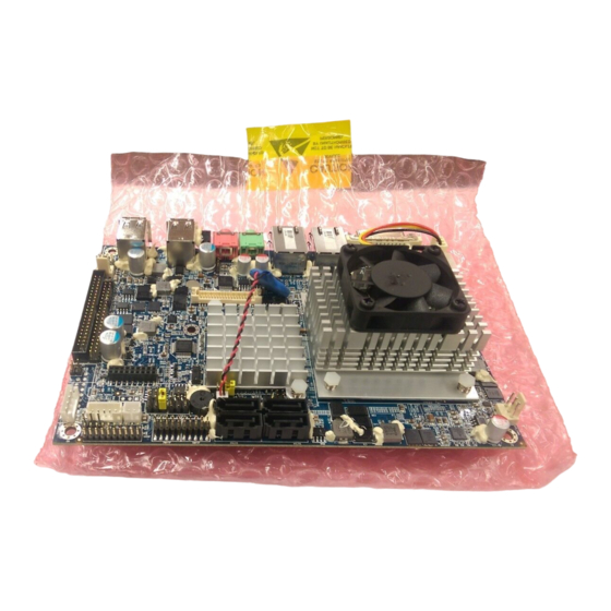
Page 16: Product Overview
EPI-QM57 2.1 Product Overview 16 EPI-QM57 User’s Manual... -
Page 17: Installation Procedure
Note: Make sure the heat sink and the CPU top surface are in total contact to avoid CPU overheating problem that would cause the system to hang or unstable EPI-QM57 User’s Manual 17... -
Page 18: Main Memory
EPI-QM57 2.2.1 Main Memory EPI-QM57 provides one 204-pin SODIMM non-ECC socket support up to DDR3 800/ 1066 SDRAM. The total maximum memory size is 4GB. SODIMM (Rear side) Make sure to unplug the power supply before adding or removing SODIMMs or other system components. - Page 19 (2) Static electricity can damage the electronic components of the computer or optional boards. Before starting these procedures, ensure that you are discharged of static electricity by touching a grounded metal object briefly. EPI-QM57 User’s Manual 19...
-
Page 20: Jumper And Connector List
Serial port 1 - Ring, +5V, +12V power 3 x 2 header, pitch 2.54mm JRI1 select Touch panel connector 3 x 1 header, pitch 2.54mm JTOUCH_SEL1 AT/ATX mode select 2 x 1 wafer, pitch 2.0mm PWR_MSEL1 20 EPI-QM57 User’s Manual... - Page 21 2 x 2 wafer, pitch 4.2mm PWRCON1 Serial ATA connector 1 SATA1 Serial ATA connector 2 SATA2 Serial ATA connector 3 SATA3 Serial ATA connector 4 SATA4 System Fan connector 3 x 1 wafer, pitch 2.54mm SYS_FAN1 VGA connector VGA1 EPI-QM57 User’s Manual 21...
-
Page 22: Setting Jumpers & Connectors
EPI-QM57 2.4 Setting Jumpers & Connectors 2.4.1 Clear CMOS (JBAT1) Protect* COMS *Default 2.4.2 Serial port 1 - Ring, +5V, +12V power select (JRI1) Ring* +12V * Default 22 EPI-QM57 User’s Manual... -
Page 23: Miscellaneous Setting Connector (Jfp1)
User’s Manual 2.4.3 Miscellaneous setting connector (JFP1) Master Slave* Signal PWBT 1, 2 *Default RST# 3, 4 PWR-LED 5, 6 HDD-LED 7, 8 CF SEL 9, 10 Short Master COPEN# 11, 12 EPI-QM57 User’s Manual 23... -
Page 24: Touch Panel Connector (Jtouch_Sel1)
EPI-QM57 2.4.4 Touch panel connector (JTOUCH_SEL1) 4/ 8W * Default 2.4.5 AT/ATX mode select (PWR_MSEL1) * Default 24 EPI-QM57 User’s Manual... -
Page 25: Battery Connector (Bbat1)
User’s Manual 2.4.6 Battery connector (BBAT1) Signal VBAT 2.4.7 Audio connector (CN1) Signal LIN1_R LIN1_JD LIN1_L EPI-QM57 User’s Manual 25... -
Page 26: Cpu Fan / System Fan Connector (Cpu_Fan1/ Sys_Fan1)
EPI-QM57 2.4.8 CPU fan / System fan connector (CPU_FAN1/ SYS_FAN1) Signal CPU_FAN_PWR/ SYS_FAN_PWR CPUFANIN/ SYSFANIN 2.4.9 PS/2 keyboard & mouse connector (JKB/MS1) Signal Signal 26 EPI-QM57 User’s Manual... -
Page 27: Primary Ide Connector (Ide1)
Primary IDE connector (IDE1) Signal PIN PIN Signal IDERST_IDE IDE_PDD7 IDE_PDD8 IDE_PDD6 IDE_PDD9 IDE_PDD5 IDE_PDD10 IDE_PDD4 IDE_PDD11 IDE_PDD3 IDE_PDD12 IDE_PDD2 IDE_PDD13 IDE_PDD1 IDE_PDD14 IDE_PDD0 IDE_PDD15 IDE_PDDREQ IDE_PDIOW# IDE_PDIOR# IDE_PDIORDY PCSEL IDE_PDDACK# INT_IRQ14 IDE_PDA1 IDE_PDIAG IDE_PDA0 IDE_PDA2 IDE_PDCS1# IDE_PDCS3# IDE_ACT# EPI-QM57 User’s Manual 27... -
Page 28: Serial Port 2 In Rs-422/485 Mode Connector (J422/485)
EPI-QM57 2.4.11 Serial port 2 In RS-422/485 mode connector (J422/485) Signal Signal J422/485 is available after Note: modifying the mode of COM2 in BIOS setting. 2.4.12 HD power connector (HD_PWR) Signal 28 EPI-QM57 User’s Manual... -
Page 29: Lcd Inverter Connector 1/ 2 (Jbkl1/ Jbkl2)
LCD Inverter Connector 1/ 2 (JBKL1/ JBKL2) JBKL2 JBKL2 JBKL1 Signal Signal BRIGHT BLK_ON +12V +12V 2.4.13.1 Signal Description – LCD Inverter Connector (JBKL1) Signal Signal Description BRIGHT Vadj = 0.75V ~ 4.25V (Recommended: 4.7KΩ, >1/16W) BLK_ON LCD backlight ON/OFF control signal EPI-QM57 User’s Manual 29... -
Page 30: 5Vsb Connector In Atx (Pwr_Sb1)
EPI-QM57 2.4.14 5VSB connector in ATX (PWR_SB1) Signal PS_ON# ATX5VSB 2.4.15 Serial port 1/ 2 connector (JCOM1/ JCOM2) JCOM2 JCOM1 Signal Signal TXDD RXDD 30 EPI-QM57 User’s Manual... -
Page 31: Irda Connector (Jir1)
User’s Manual 2.4.16 IrDA connector (JIR1) Signal EPI-QM57 User’s Manual 31... -
Page 32: Touch Panel Connector (Jtouch1)
EPI-QM57 2.4.17 Touch panel connector (JTOUCH1) Signal TOUCH_GND SENSE 4-WIRE 5-WIRE 8-WIRE Top Excite Bottom Bottom Excite Left Left Excite Right Right Excite Sense Top Sense Bottom Sense Left Sense Right Sense 32 EPI-QM57 User’s Manual... -
Page 33: General Purpose I/O Connector (Jdio1)
User’s Manual 2.4.18 General purpose I/O connector (JDIO1) Signal PIN PIN Signal SMBDATA_MAIN SMBCLK_MAIN DIO_GP17 DIO_GP27 DIO_GP16 DIO_GP26 DIO_GP15 DIO_GP25 DIO_GP14 DIO_GP24 DIO_GP13 DIO_GP23 DIO_GP12 DIO_GP22 DIO_GP11 DIO_GP21 DIO_GP10 DIO_GP20 EPI-QM57 User’s Manual 33... -
Page 34: For Express Card Daughter Board Use (Jexp1)
2.4.19 For Express Card Daughter Board Use (JEXP1) Signal PIN PIN Signal GN-2 PER-P0 PET-P0 PER-N0 PET-N0 REFCLK+ CPPE# REFCLK- +3.3V PERST# +3.3VAUX SMBDATA WAKE# SMBCLK +1.5V USBD+ GND-1 USBD- 2.4.20 Power connector (PWRCON1) Signal Signal 34 EPI-QM57 User’s Manual... -
Page 35: Spi Connector (Jspi1)
SPISO SPI_CLK SPI_CS#0 +3.3V 2.4.22 USB connector 4&5/ 6&7 (JUSB1/ JUSB2) Signal Signal USB_DN4/ 6 USB_DP4/ 6 USB_DP5/ 7 USB_DN5/ 7 Wrong USB cable configuration with Note: your USB devices might cause your USB devices damaged EPI-QM57 User’s Manual 35... -
Page 36: Lvds Connector (Jlvds1)
EPI-QM57 2.4.23 LVDS connector (JLVDS1) Signal Signal +12V +12V CLK2M CLK1M CLK2P CLK1P YA7M YA6M YA7P YA6P YA5M YA4M YA5P YA4P YA3M YA2M YA3P YA2P YA1M YA0M YA1P YA0P SPCLK SPDATA +3.3V +3.3V 36 EPI-QM57 User’s Manual... - Page 37 User’s Manual 3. BIOS Setup EPI-QM57 User’s Manual 37...
-
Page 38: Introduction
If you do not press the keys at the correct time and the system does not boot, an error message will be displayed and you will again be asked to. Press F1 to Continue, DEL to enter SETUP 38 EPI-QM57 User’s Manual... -
Page 39: Using Setup
Note: Some of the navigation keys differ from one screen to another. • To Display a Sub Menu Use the arrow keys to move the cursor to the sub menu you want. Then press <Enter>. A “ ” pointer marks all sub menus. EPI-QM57 User’s Manual 39... -
Page 40: Getting Help
Award and your systems manufacturer to provide the absolute maximum performance and reliability. Even a seemingly small change to the chipset setup has the potential for causing you to use the override. 40 EPI-QM57 User’s Manual... -
Page 41: Bios Setup
This section allows you to record some basic hardware configurations in your computer and set the system clock. 3.5.1.1 System Language This option allows choosing the system default language. 3.5.1.2 System Date Use the system time option to set the system time. Manually enter the hours, minutes and seconds. EPI-QM57 User’s Manual 41... -
Page 42: System Time
Visit the Avalue website (www.avalue.com.tw) to download the latest product and BIOS information. 3.5.2 Advanced Menu This section allows you to configure your CPU and other system devices for basic operation through the following sub-menus. 42 EPI-QM57 User’s Manual... -
Page 43: Pci Subsystem Settings
Enable, If ENABLED allows generation of Extended PERR# Generation Disable Synchronization patterns. Enable, Enables or Disables PCI Devices to Generate SERR# Generation Disable SERR#. Enable, Enables or Disables PCI Express Device Relaxed Ordering Disable Relaxed Ordering. EPI-QM57 User’s Manual 43... - Page 44 Set the ASPM Level: Force L0 – Force all links Auto, to L0 State: Auto – BIOS auto configure: ASPM Support Force L0 DISABLE – Disables ASPM Enable, If ENABLED allows generation of Extended Extended Synch Disable Synchronization patterns. 44 EPI-QM57 User’s Manual...
-
Page 45: Acpi Settings
OS. Suspend Disable, Select the highest ACPI sleep state the S1 (CUP Stop Clock), system will enter, when the SUSPEND button ACPI Sleep State S3 (Suspend to RAM) is pressed. EPI-QM57 User’s Manual 45... -
Page 46: Cpu Configuration
Power Technology Custom Turbo-XE Mode Processor TDC Limit in 1/8 A granularity. 0 means using the TDC Limit factory-configured value. Turbo-XE Mode Processor TDP Limit in 1/8 W granularity. 0 means using the TDP Limit factory-configured value. 46 EPI-QM57 User’s Manual... -
Page 47: Sata Configuration
It allows you to select the operation SATA mode AHCI mode, mode for SATA controller. RAID mode Disable, Enable/ Disable Serial ATA Enhanced, Serial-ATA Controller 0 Controller 0. Compatible Disable, Enable/ Disable Serial ATA Serial-ATA Controller 1 Enhanced Controller 0. EPI-QM57 User’s Manual 47... -
Page 48: Thermal Configuration
MCH/ GfX offset for calculating MCH/ MGTA_OFFSET GfX Temperature. Disabled, MCH Temperature Read Enable. MCH Temp Read Enabled Disabled, PCH Temperature Read Enable. PCH Temp Read Enabled Disabled, CPU Energy Read Enable. CPU Energy Read Enabled 48 EPI-QM57 User’s Manual... -
Page 49: Intel Igd Swsci Opregion
DVMT/BOTH DVMT/ Fixed Memory Maximum operating mode. VBIOS Default, CRT, This feature allows you to select LVDS, the display device when you boot IGD – Boot Type CRT+LVDS, up the system. DVI, CRT+DVI EPI-QM57 User’s Manual 49... - Page 50 Spread Spectrum Clock Chip Software: Spread is controlled by Software BIOS. Valid only for ACPI. Legacy = ALS Enabled, Support through the IGD INT10 ALS Support Disabled function. ACPI = ALS support through an ACPI ALS Driver. 50 EPI-QM57 User’s Manual...
-
Page 51: Intel Tdt (At-P) Configuration
User’s Manual 3.5.2.7 Intel TDT (AT-p) Configuration Item Option Description Enabled, Enable/ Disable TDT in BIOS for Disabled testing only. Set the number of times Recovery TDT Recovery attemped will be allowed. EPI-QM57 User’s Manual 51... -
Page 52: Intel Txt (Lt) Configuration
EPI-QM57 3.5.2.8 Intel TXT (LT) Configuration 3.5.2.9 USB Configuration The USB configuration menu is used to read USB configuration information and configure the USB setting. 52 EPI-QM57 User’s Manual... -
Page 53: Legacy Usb Support
3.5.2.9.4 Mass Storage Devices This item allows you to set up mass storage devices. The choices: Auto, Floppy, Forced FDD, Hard-Disk, CD-ROM. 3.5.2.10 H/W Monitor The H/W Monitor mean shows the operating temperature, fan speeds and system voltages. EPI-QM57 User’s Manual 53... -
Page 54: Super Io Configuration
EPI-QM57 3.5.2.11 Super IO Configuration You can use this item to set up or change the Super IO configuration for FDD controllers, parallel ports and serial ports. Please refer to 3.5.2.12.1 and 3.5.2.12.2 for more information. 54 EPI-QM57 User’s Manual... -
Page 55: Serial Port 0 Configuration
Serial Port Disabled enable or disable the serial port. IO=3F8h; IRQ=4, IO=3F8h; IRQ=3,4,5,6,7,10,11,12 Use the change Settings option to IO=2F8h; IRQ=3,4,5,6,7,10,11,12 change the serial port IO port Change Settings IO=3E8h; IRQ=3,4,5,6,7,10,11,12 address and interrupt address. IO=2E8h; IRQ=3,4,5,6,7,10,11,12 EPI-QM57 User’s Manual 55... -
Page 56: Serial Port 1 Configuration
Use the change Settings option to IO=2F8h; IRQ=3,4,5,6,7,10,11,12 change the serial port IO port Change Settings IO=3E8h; IRQ=3,4,5,6,7,10,11,12 address and interrupt address. IO=2E8h; IRQ=3,4,5,6,7,10,11,12 UART 232, Change the Serial Port as RS232/ UART 422, UART 232 422 485 422/ 485 UART485 56 EPI-QM57 User’s Manual... -
Page 57: Intelligent Power Sharing
User’s Manual 3.5.2.12 Intelligent Power Sharing Intelligent Power Sharing configuration menu. (NOTE: DTS must be enabled for Power Sharing to function.) The choices: Enabled, Disabled. EPI-QM57 User’s Manual 57... -
Page 58: Amt Configuration
Use AMT option to enable/ Disabled disable the Intel® AMT function. You can use this item to perform Enabled, AMT/ME unconfigure without Unconfigure AMT/ME Disabled password operation. Enabled, This option will determine watch WatchDog Timer Disabled dog timer. 58 EPI-QM57 User’s Manual... -
Page 59: Advanced Chipset Features
User’s Manual 3.5.3 Advanced Chipset Features This setting configures the north bridge, south bridge and ME subsystem. EPI-QM57 User’s Manual 59... -
Page 60: North Bridge
This option will determine Low Low MMIO Align 1024M MMIO resources align. IGD, PCI/IGD, This item allows you to select PCI/PEG, which graphics controller to use Initate Graphic Adapter PEG/IGD, as the primary boot device. PEG/PCI 60 EPI-QM57 User’s Manual... -
Page 61: South Bridge
Disable Use the Azalia HD Audio option to Enable, enable or disable the High Azalia HD Audio Disable Definition Audio controller. Enable, This item helps to enable or High Precision Timer Disable disable high precision timer. EPI-QM57 User’s Manual 61... - Page 62 This item allows you to re-assign the function numbers on a port by port basis. You can disable/hide any root port and have still have functions 0 thru N-1 where N is the total number of enabled root ports. The choices: Disable, Enable, Auto. 62 EPI-QM57 User’s Manual...
- Page 63 User’s Manual 3.5.3.2.2 USB Configuration The USB Configuration menu is used to read USB configuration information and configure the USB settings. The choices: Disable, Enable. EPI-QM57 User’s Manual 63...
-
Page 64: Me Subsystem
End of Post Message Disable end of post message of the ME Subsystem. Use the Execute MEBx option to Enable, enable or disable the Intel® Execute MEBx Disable Management Engine BIOS extension (MEBx). 64 EPI-QM57 User’s Manual... -
Page 65: Boot
RT code is executed above 1MB. Force BIOS, Set display mode for Option ROM. Option ROM Messages Keep Current Enable, Enable: Allows Option ROMs to trap int 19. Interrupt 19 Capture Disable EPI-QM57 User’s Manual 65... -
Page 66: Security
Use the Security menu to set system and user password. 3.5.5.1 Administrator Password Use the Administrator Password to set or change a administrator password. 3.5.5.2 User Password Use the User Password to set or change a user password. 66 EPI-QM57 User’s Manual... -
Page 67: Save & Exit
User’s Manual 3.5.6 Save & Exit 3.5.6.1 Save changes and exit EPI-QM57 User’s Manual 67... -
Page 68: Discard Changes And Exit
EPI-QM57 3.5.6.2 Discard Changes and Exit 3.5.6.3 Save changes and Reset 68 EPI-QM57 User’s Manual... -
Page 69: Discard Changes And Reset
User’s Manual 3.5.6.4 Discard Changes and Reset 3.5.6.5 Save changes EPI-QM57 User’s Manual 69... -
Page 70: Discard Changes
EPI-QM57 3.5.6.6 Discard Changes 3.5.6.7 Restore Defaults 70 EPI-QM57 User’s Manual... -
Page 71: Save As User Defaults
User’s Manual 3.5.6.8 Save as User Defaults 3.5.6.9 Restore User Defaults EPI-QM57 User’s Manual 71... -
Page 72: Drivers Installation
EPI-QM57 4. Drivers Installation Note: Installation procedures and screen shots in this section are for your reference and may not be exactly the same as shown on your screen. 72 EPI-QM57 User’s Manual... -
Page 73: Install Chipset Driver (For Intel Qm57)
Windows XP operation system. If the warning message appears while the installation Step 3. Click Next. process, click Continue to go on. Step1. Locate 「\Driver_Chipset\Intel\ OM57\ \infinst_autol.exe」. Step 4. Click Finish to complete setup. Step 2. Click Next. EPI-QM57 User’s Manual 73... -
Page 74: Install Display Driver (For Intel Qm57)
Note: The installation procedures and screen shots in this section are based on Windows XP operation system. Step 3. Click Yes. Step 1. Locate「Driver_Video\Intel\ Step 4. Click Next. QM57\Setup.exe」. Step 2. Click Next. Step 5. Click Finish to complete setup. 74 EPI-QM57 User’s Manual... -
Page 75: Install Audio Driver (For Realtek Alc883)
Windows 2000 operation system. Step 3. Select Next to the next step. Step 4. Click Finish to complete the Step 1. Locate 「\Driver_Audio\Intel\ setup. 6300ESB ALC883\setup.exe」. Step 2. The program executes the Setup automatically. EPI-QM57 User’s Manual 75... -
Page 76: Install Ethernet Driver (For Intel 82574L/ 82577Lm)
Step 3. Click Next to run the installation. based on Windows XP operation system. Step 1. Locate 「\Driver_Gigabit\Intel\ Step 4. Click Accept to continue. 82574L or 82577LM」and choose your system OS. Step 2. Click Next. Step 5. Click Next. 76 EPI-QM57 User’s Manual... - Page 77 User’s Manual Step 5. Click Install to next step. Step 6. Click Next to next step. Step 7. Click Finish to complete the setup. EPI-QM57 User’s Manual 77...
-
Page 78: Mechanical Drawing
EPI-QM57 5. Mechanical Drawing 78 EPI-QM57 User’s Manual... - Page 79 User’s Manual Unit: mm EPI-QM57 User’s Manual 79...
- Page 80 EPI-QM57 Unit: mm 80 EPI-QM57 User’s Manual...
Need help?
Do you have a question about the EPI-QM57 and is the answer not in the manual?
Questions and answers