
Related Manuals for Avalue Technology EPX-EHLP


Summary of Contents for Avalue Technology EPX-EHLP
- Page 1 EPX-EHLP Intel® Elkhart Lake 2.5” Pico ITX motherboard User’s Manual Ed – 10 February 2023 Part No. E2047EPHP01R...
- Page 2 Disclaimer Avalue Technology Inc. reserves the right to make changes, without notice, to any product, including circuits and/or software described or contained in this manual in order to improve design and/or performance. Avalue Technology assumes no responsibility or liability for the...
- Page 3 Applications that are described in this manual are for illustration purposes only. Avalue Technology Inc. makes no representation or warranty that such application will be suitable for the specified use without further testing or modification.
- Page 4 A product returned without proof of the purchase date is not eligible for warranty service. Write the RMA number visibly on the outside of the package and ship it prepaid to your dealer. 4 EPX-EHLP User’s Manual...
-
Page 5: Table Of Contents
3.6.1.3 System Time ........................31 3.6.2 Advanced Menu ..........................31 3.6.2.1 CPU Configuration ....................... 32 3.6.2.2 Power & Performance ......................32 3.6.2.2.1 CPU - Power Management Control ..................33 3.6.2.2.2 GT - Power Management Control ..................34 EPX-EHLP User’s Manual... - Page 6 Save Changes and Reset ....................57 3.6.6.2 Discard Changes and Reset ....................57 3.6.6.3 Restore Defaults ........................58 3.6.6.4 Launch EFI Shell from filesystem device ................58 4. Drivers Installation....................... 59 Install Chipset Driver ....................60 Install VGA Driver ....................61 6 EPX-EHLP User’s Manual...
- Page 7 User’s Manual Install Ethernet Driver ....................62 Install HID Driver ..................... 64 Install ME Driver ...................... 65 5. Mechanical Drawing ....................66 EPX-EHLP User’s Manual...
-
Page 8: Getting Started
1.2 Packing List Before you begin installing your single board, please make sure that the following materials have been shipped: 1 x EPX-EHLP motherboard 8 EPX-EHLP User’s Manual... -
Page 9: Document Amendment History
User’s Manual 1.3 Document Amendment History Revision Date Comment January 2023 Avalue Initial Release February 2023 Avalue Update System Specifications EPX-EHLP User’s Manual... -
Page 10: Manual Objectives
We strongly recommend that you study this manual carefully before attempting to set up EPX-EHLP or change the standard configurations. Whilst all the necessary information is available in this manual we would recommend that unless you are confident, you contact your supplier for guidance. -
Page 11: System Specifications
1 x M.2 Type E 2230 support WiFi module, USB 2.0 Signal Storage 1 x M.2 Type B 2242/2260 PCI-e or SATA SSD Edge I/O 2 x Intel® I225/i226LM(I225/i226IT for wide temp version) 2.5 Gigabit Ethernet EPX-EHLP User’s Manual 11... - Page 12 Power Requirement DC in +12V Single power ATX Support S0, S3, S4, S5 ACPI ACPI 5.1 Compliant Power Mode AT / ATX mode Switchable Through Jumper Operating Temp. 0~60°C (32~140°F) Elkhart Lake J Series CPU SKU 12 EPX-EHLP User’s Manual...
- Page 13 Non Operation mode Test Frequency : 5-500Hz Test Axis : X,Y and Z axis 30 minutes per each axis IEC 60068-2-64 Test:Fh Packing Drop Drop Test Reference ISTA 2A, Method : IEC-60068-2-32 Test: Ed Drop Test EPX-EHLP User’s Manual 13...
- Page 14 EPX-EHLP User’s Manual 1 One corner , three edges, six faces 2 ISTA 2A, IEC-60068-2-32 Test:Ed OS Information Win10 64bit, Linux Note: Specifications are subject to change without notice. 14 EPX-EHLP User’s Manual...
-
Page 15: Architecture Overview-Block Diagram
User’s Manual 1.6 Architecture Overview—Block Diagram The following block diagram shows the architecture and main components of EPX-EHLP. EPX-EHLP User’s Manual 15... -
Page 16: Hardware Configuration
EPX-EHLP User’s Manual 2. Hardware Configuration 16 EPX-EHLP User’s Manual... -
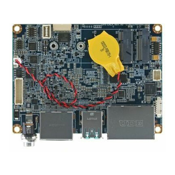
Page 17: Product Overview
User’s Manual 2.1 Product Overview EPX-EHLP User’s Manual 17... -
Page 18: Jumper And Connector List
15 x 2 wafer, pitch 1.00 mm JLVDS1 General purpose I/O connector 6 x 1 wafer, pitch 1.25 mm JDIO1 JSPI_EC connector 10 x 1 wafer, pitch 1.00 mm JSPI_EC1 JESPI connector 6 x 2 wafer, pitch 1.00 mm JESPI1 18 EPX-EHLP User’s Manual... - Page 19 Please note interferance may occcur if customer may use both Key E & Key B modules together. It is recommend to use standard 1.5mm thickness for Key E module. Bottom of Key B module height shall not be thicker than 1.1mm. EPX-EHLP User’s Manual 19...
-
Page 20: Setting Jumpers & Connectors
2.3 Setting Jumpers & Connectors 2.3.1 AT/ATX mode selector (AT_CMOS1) AT/ATX mode AT mode* ATX mode *Default 2.3.2 JESPI connector (JESPI 1) Signal PIN PIN Signal CN_ESPI_IO0 +3.3_ ESPI CN_ESPI_IO1 PLT_RST_BUT# CN_ESPI_IO2 ESPI_CS#0 CN_ESPI_IO3 CN_ESPI_CLK ESPI_RST ESPI_ALERT#0 20 EPX-EHLP User’s Manual... -
Page 21: General Purpose I/O Connector (Jdio1)
User’s Manual 2.3.3 General purpose I/O connector (JDIO1) Signal EC_DI1 EC_DI0 EC_DO1 EC_DO0 +3.3V 2.3.4 Miscellaneous setting connector (JFP1) Signal PIN PIN Signal PWR_LED+ HDD_LED+ PWR_LED# HDD_LED# PWR_BTN_IN_EC# PMC_RSTBTN# EPX-EHLP User’s Manual 21... -
Page 22: Serial Port 1 Connector (Jcom1)
Serial port 1 connector (JCOM1) Signal PIN PIN Signal COM_DCD#_TXN_1 COM_RXD#_TXP_1 COM_TXD_RXP_1 COM_DTR#_RXN_1 COM_DSR#_1 COM_RTS#_1 COM_CTS#_1 COM_RI#_1 2.3.6 Serial port 2 connector (JCOM2) Signal PIN PIN Signal COM_DCD# _2 COM_RXD#_2 COM_TXD_ 2 COM_DTR#_2 COM_DSR#_2 COM_RTS#_2 COM_CTS#_2 COM_RI#_2 22 EPX-EHLP User’s Manual... -
Page 23: Usb Connector (Jusb 1)
User’s Manual 2.3.7 USB connector (JUSB 1) Signal PIN PIN Signal +5A_USB23 USB_R_DN2 USB_R_DN3 USB_R_DN2 USB_R_DN3 USB_R_DN4 USB_R_DN5 USB_R_DN4 USB_R_DN5 +5A_USB45 2.3.8 SPI header (JSPI_EC1) Signal EC_SMDAT_DBG EC_SMCLK_DBG SPI_HOLD# SPI_MOSI SPI_MISO SPI_CLK SPI_CS#0 +V3.3A_SPI EPX-EHLP User’s Manual 23... -
Page 24: Battery Connector (Bt1)
EPX-EHLP User’s Manual 2.3.9 Battery connector (BT1) Signal +3.3VSB 24 EPX-EHLP User’s Manual... -
Page 25: Lvds Connector (Jlvds1)
+V3.3_LVDS +V5_LVDS LVDS_DATA1_P 10 LVDS_DATA0_P LVDS_DATA1_N 11 12 LVDS_DATA0_N LVDS_DATA3_P 15 16 LVDS_DATA2_P LVDS_DATA3_N 17 18 LVDS_DATA2_N LVDS_BKLTEN LVDS_CLK1_P VBRIGHT LVDS_CLK1_N +12V Note: Mainboard Connector: Aces 50238-03071-003 or Equivalent User Side Connector: WELL-LIN 1010-H-2X15P or Equivalent EPX-EHLP User’s Manual 25... -
Page 26: Bios Setup
EPX-EHLP User’s Manual 3.BIOS Setup 26 EPX-EHLP User’s Manual... -
Page 27: Introduction
If the message disappears before you respond and you still wish to enter Setup, restart the system to try again by turning it OFF then ON or pressing the "RESET" button on the system case. You may also restart by simultaneously pressing <Ctrl>, <Alt>, and <Delete> keys. EPX-EHLP User’s Manual 27... -
Page 28: Using Setup
Note: Some of the navigation keys differ from one screen to another. To Display a Sub Menu Use the arrow keys to move the cursor to the sub menu you want. Then press <Enter>. A “” pointer marks all sub menus. 28 EPX-EHLP User’s Manual... -
Page 29: Getting Help
BIOS Vendor and your systems manufacturer to provide the absolute maximum performance and reliability. Even a seemingly small change to the chipset setup has the potential for causing you to use the override. EPX-EHLP User’s Manual 29... -
Page 30: Bios Setup
<Enter> to accept and enter the sub-menu. 3.6.1 Main Menu This section allows you to record some basic hardware configurations in your computer and set the system clock. 30 EPX-EHLP User’s Manual... -
Page 31: System Language
Visit the Avalue website (www.avalue.com.tw) to download the latest product and BIOS information. 3.6.2 Advanced Menu This section allows you to configure your CPU and other system devices for basic operation through the following sub-menus. EPX-EHLP User’s Manual 31... -
Page 32: Cpu Configuration
When enabled, a VMM can utilize the additional Intel (VMX) Virtualization Disabled, hardware capabilities provided by Vanderpool Technology Enabled[Default] Technology. All[Default] Number of cores to enable in each processor Active Processor Cores /1/2/3/4/5/6/7/8 package. 3.6.2.2 Power & Performance 32 EPX-EHLP User’s Manual... -
Page 33: Cpu - Power Management Control
Enable/Disable processor Turbo Mode (requires EMTTM Turbo Mode Enabled[Default], enabled too). Auto means enabled. Disabled[Default] Enable/Disable CPU Power Management. Allows CPU to C states go to C states when it’s not 100% utilized. Enabled, 3.6.2.2.1.1 View/Configure Turbo Options EPX-EHLP User’s Manual 33... -
Page 34: Gt - Power Management Control
Cheak to enable render standby support. Standby) Enabled[Default], Default Max Frequency[Default], 100Mhz/150Mhz/200Mhz/250Mhz/300Mhz/ Maximum GT 350Mhz/400Mhz/450Mhz/500Mhz/550Mhz/ Auto Updated frequency 600Mhz/650Mhz/700Mhz/750Mhz/800Mhz/ 850Mhz/900Mhz/950Mhz/1000Mhz/ 1050Mhz/1100Mhz/1150Mhz/1200Mhz Disable Turbo GT Disabled[Default], Enabled: Disable Turbo GT frequency. frequency Enabled Disabled: GT frequency is not limited 34 EPX-EHLP User’s Manual... -
Page 35: Pch-Fw Configuration
When Disabled ME will not be unconfigured on RTC Clear Enabled[Default], 3.6.2.3.1 Firmware Update Configuration Item Options Description Disabled[Default], Me FW Image Re-Flash Enable/Disable Me FW Image Re-Flash function. Enabled Disabled FW Update Enable/Disable ME FW Update function. Enabled[Default], EPX-EHLP User’s Manual 35... -
Page 36: Ptt Configuration
3.6.2.4 Trusted Computing Item Options Description Enables or Disables BIOS support for security Disable Security Device Support devices. O.S. will not show Security Device. TCG EFI Enable[Default] protocol and INT1A interface will not be available. 36 EPX-EHLP User’s Manual... -
Page 37: Acpi Settings
SUSPEND button is pressed. [Default] 3.6.2.6 IT5571 Super IO Configuration You can use this item to set up or change the IT5571 Super IO configuration for serial ports. Please refer to 3.6.2.6.1 for more information. EPX-EHLP User’s Manual 37... -
Page 38: Serial Port 1 Configuration
UART 232 422 485 UART 422 Change the Serial Port as RS232/422/485 UART 485 Auto[Default] Non INT+EXT R INT_EXT R mode EXT R Enable switches for internal and external resistors INT R INT+EXT R 3.6.2.6.2 Serial Port 2 Configuration 38 EPX-EHLP User’s Manual... -
Page 39: H/W Monitor
Enable or disable System wake on alarm event. Disabled[Default], Select FixedTime, system will wake on the Wake system from S5 Fixed Time hr::min::sec specified. Select Dynamic Time, System Dynamic Time will wake on the current time + Increase minute(s). EPX-EHLP User’s Manual 39... -
Page 40: Serial Port Console Redirection
The USB Configuration menu helps read USB information and configures USB settings. Item Options Description Enables Legacy USB support. AUTO option disables Enabled[Default] legacy support if no USB devices are connected. Legacy USB Support Disabled DISABLE option will keep USB devices available only Auto for EFI applications. 40 EPX-EHLP User’s Manual... -
Page 41: Network Stack Configuration
Optical drives are emulated as ‘CDROM’, drives with no Hard Disk media will be emulated according to a drive type. CD-ROM 3.6.2.11 Network Stack Configuration Item Options Description Enabled Network Stack Enable/Disable UEFI Network Stack Disabled[Default] EPX-EHLP User’s Manual 41... -
Page 42: Nvme Configuration
EPX-EHLP User’s Manual 3.6.2.12 NVMe Configuration 3.6.3 Chipset 42 EPX-EHLP User’s Manual... -
Page 43: System Agent (Sa) Configuration
Enable/Disable above 4GB MemoryMappedIO BIOS Above 4GB MMIO BIOS Disabled[Default], assignment This is enabled automatically when assignment Enabled Aperture Size is set to 2048MB. 3.6.3.1.1 Memory Configuration Item Option Description Enabled In-Band ECC Enable/Disable In-Band ECC Disabled[Default], EPX-EHLP User’s Manual 43... -
Page 44: Graphics Configuration
Select the GTT Size 8MB[Default] 128MB Select the Aperture Size Note : Above 4GB MMIO BIOS 256MB[Default] assignment is automatically enabled when selecting Aperture Size 512MB 2048MB aperture. To this feature, please disable CSM 1024MB Support. 44 EPX-EHLP User’s Manual... -
Page 45: Pch-Io Configuration
User’s Manual 3.6.3.2 PCH-IO Configuration 3.6.3.2.1 PCI Express Configuration EPX-EHLP User’s Manual 45... -
Page 46: Pci Express Root Port 1(M.2 Keyb)
State AUTO - BIOS auto configure DISABLE - L0sL1 Disables ASPM Auto Disabled[Default] L1 Substates L1.1 PCI Express L1 Substates settings. L1.1 & L1.2 Disabled[Default] Enable/Disable Precision Time Measurement Enabled Auto[Default] Gen1 PCIe Speed Configure PCIe Speed Gen2 Gen3 46 EPX-EHLP User’s Manual... -
Page 47: Pci Express Root Port 3(M.2 Keye)
State AUTO - BIOS auto configure DISABLE - L0sL1 Disables ASPM Auto Disabled[Default] L1 Substates L1.1 PCI Express L1 Substates settings. L1.1 & L1.2 Disabled[Default] Enable/Disable Precision Time Measurement Enabled Auto[Default] Gen1 PCIe Speed Configure PCIe Speed Gen2 Gen3 EPX-EHLP User’s Manual 47... -
Page 48: Pci Express Root Port 4(Lan1-I225/226)
State AUTO - BIOS auto configure DISABLE - L0sL1 Disables ASPM Auto Disabled[Default] L1 Substates L1.1 PCI Express L1 Substates settings. L1.1 & L1.2 Disabled[Default] Enable/Disable Precision Time Measurement Enabled Auto[Default] Gen1 PCIe Speed Configure PCIe Speed Gen2 Gen3 48 EPX-EHLP User’s Manual... -
Page 49: Pci Express Root Port 7(Lan2-I225/226)
State AUTO - BIOS auto configure DISABLE - L0sL1 Disables ASPM Auto Disabled[Default] L1 Substates L1.1 PCI Express L1 Substates settings. L1.1 & L1.2 Disabled[Default] Enable/Disable Precision Time Measurement Enabled Auto[Default] Gen1 PCIe Speed Configure PCIe Speed Gen2 Gen3 EPX-EHLP User’s Manual 49... -
Page 50: Pci Express Root Port 7(Lan2-I225/226)
Enabled = keep clock Disabled enabledeven if unused. Disabled = Disable clock. Platform-POR = CLKREQ signal is assigned to Platform-POR[Default] ClkReq for Clock4 CLKSRC according to board layout. Disabled = Disabled CLKREQ will not be used. 50 EPX-EHLP User’s Manual... -
Page 51: Sata Configuration
Enable/Disable SATA Port 1 DevSlp. For DevSlp to work, both hard drive and SATA port Disabled[Default], SATA Port 1 DevSlp need to support DevSlp function, otherwise an Enabled unexpected behavior might happen. Please check board design before enabling it. EPX-EHLP User’s Manual 51... -
Page 52: Usb Configuration
Device Connection to the controller. 3.6.3.2.4 HD Audio Configuration Item Options Description Control Detection of the HD-Audio device. Disabled = Enabled[Default], HD Audio HDA will be unconditionally disabled Enabled = HDA will Disabled be unconditionally enabled. 52 EPX-EHLP User’s Manual... -
Page 53: Board Configuration
Enabled Off[Default], PWR-On After PWR-Fail AC loss resume. Last state Disabled Wake Up by Ring Wake Up by Ring from S3/S4/S5 Enabled[Default], Disabled[Default], Watch Dog 30 sec/40 sec/50 sec/ Select WatchDog. 1 min/2 min/10 min/30 min EPX-EHLP User’s Manual 53... -
Page 54: Security
Disabled USB Standby Power Enable/Disable USB Standby Power during S3/S4/S5 Enabled[Default], Disabled[Default], SHOW DMI INFO SHOW DMI INFO Enabled 3.6.4 Security Item Description Administrator Password Set Administrator Password User Password Set User Password 3.6.4.1 Secure Boot 54 EPX-EHLP User’s Manual... - Page 55 The mode change requires platform reset Secure Boot mode options: Standard or Custom. In Standard[Default], Custom mode, Secure Boot Policy variables can be Secure Boot Mode Custom configured by a physically present user without full authentication EPX-EHLP User’s Manual 55...
-
Page 56: Boot
On[Default] Bootup NumLock State Select the keyboard NumLock state. Disabled[Default] Quiet Boot Enable or disable Quiet Boot option. Enabled Boot Option #1 Sets the system boot order Boot Option #2 Sets the system boot order 56 EPX-EHLP User’s Manual... -
Page 57: Save & Exit
Reset the system after saving the changes. 3.6.6.2 Discard Changes and Reset Any changes made to BIOS settings during this session of the BIOS setup program are discarded. The setup program then exits and reboots the controller. EPX-EHLP User’s Manual 57... -
Page 58: Restore Defaults
This option restores all BIOS settings to the factory default. This option is useful if the controller exhibits unpredictable behavior due to an incorrect or inappropriate BIOS setting. 3.6.6.4 Launch EFI Shell from filesystem device Attempts to Launch EFI Shell application (Shellx64.efi) from one of the available filesystem devices. 58 EPX-EHLP User’s Manual... -
Page 59: Drivers Installation
User’s Manual 4. Drivers Installation Note: Installation procedures and screen shots in this section are for your reference and may not be exactly the same as shown on your screen. EPX-EHLP User’s Manual 59... -
Page 60: Install Chipset Driver
Windows 10 operation system. If the warning message appears while the installation process, click Co Step1. Click Next. Step 3. Click Install. Step 4. Complete setup. Step 2. Click Accept. 60 EPX-EHLP User’s Manual... -
Page 61: Install Vga Driver
Windows 10 operation system. If the warning message appears while the installation process, click Co Step 3. Click Start. Step 1. Click Next. Step 4. Click Finish to complete the setup. Step 2. Click I agree. EPX-EHLP User’s Manual 61... -
Page 62: Install Ethernet Driver
If the warning message appears while the installation process, click Continue to go on. Step 3. Click Next. Step 1. Click Next Step 4. Click Next. Step 2. Click Next to proceed. Step 5. Click Install. 62 EPX-EHLP User’s Manual... - Page 63 User’s Manual Step 6. Click Finish to complete the setup. EPX-EHLP User’s Manual 63...
-
Page 64: Install Hid Driver
If the warning message appears while the installation process, click Continue to go on. Step 1. Click Next to continue setup. Step 3. Click Next. Step 4. Click Finish to complete the setup. Step 2. Click Yes. 64 EPX-EHLP User’s Manual... -
Page 65: Install Me Driver
If the warning message appears while the installation process, click Continue to go on. Step 1. Click Next to continue setup. Step 3. Click Next. Step 4. Click Finish to complete the setup. Step 2. Click Next. EPX-EHLP User’s Manual 65... -
Page 66: Mechanical Drawing
EPX-EHLP User’s Manual 5. Mechanical Drawing 66 EPX-EHLP User’s Manual... - Page 67 User’s Manual Unit: mm Unit: mm EPX-EHLP User’s Manual 67...
Need help?
Do you have a question about the EPX-EHLP and is the answer not in the manual?
Questions and answers