Allen-Bradley SLC 500 Quick Start Manual
Ethernet
Hide thumbs
Also See for SLC 500:
- Reference manual (694 pages) ,
- Manual (270 pages) ,
- Migration manual (60 pages)

Related Manuals for Allen-Bradley SLC 500


Summary of Contents for Allen-Bradley SLC 500
-
Page 1: Quick Start
Allen-Bradley Quick Start Ethernet SLC 500 Processors Experienced (Catalog Numbers 1747-L551, -L552, and -L553) Users... - Page 2 Identifies information that is critical for successful application and understanding of the product. SLC 5/05, SLC 500, and Data Highway Plus are trademarks of Rockwell Automation. RSLogix 500 and RSLinx are trademarks of Rockwell Software., Inc. Ethernet is a registered trademark of Digital Equipment Corporation, Intel, and Xerox Corporation.
-
Page 3: Table Of Contents
..... . . P–3 Allen-Bradley Support ....... - Page 4 Configuration Via BOOTP ......3–7 Using DOS/Windows BOOTP ......3–8 Install the DOS/Windows BOOTP server .
-
Page 5: Who Should Use This Manual
Manual programming, or troubleshooting control systems that use Allen-Bradley small logic controllers. You should have a basic understanding of SLC 500 products. You should understand programmable controllers and be able to interpret the ladder logic instructions required to control your application. If you do not, contact your local Allen-Bradley representative for information on available training courses before using this product. -
Page 6: Related Documentation
Allen-Bradley Small Logic Controllers and their installation and application. You may want to reference them while you are installing the SLC 500 controller. (To obtain a copy of one of these publications, contact your local Allen-Bradley office or distributor.) -
Page 7: Conventions Used In This Manual
Technical Product Assistance If you need to contact Allen-Bradley for technical assistance, please record information about the problem situation, including any error codes and state of LED indicators. If possible, please also have the following information ready: hardware series, operating system used, firmware level, and software release. -
Page 8: Your Questions Or Comments On This Manual
Publication Problem Report. If you have any suggestions for how this manual could be made more useful to you, please contact us at the address below: Allen-Bradley Company, Inc. Control and Information Group Technical Communication, Dept. A602V, T122 P.O. Box 2086 Milwaukee, WI 53201-2086 Publication 1747-10.4... -
Page 9: Slc 5/05 Processors And Ethernet Communication
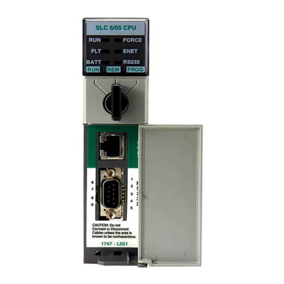
This chapter: describes SLC 5/05 processors and Ethernet communication describes SLC 5/05 performance considerations illustrates SLC 5/05 hardware features explains processor status LED operation explains keyswitch operation SLC 5/05 Processors and Ethernet is a local area network that provides communication Ethernet Communication between various devices at 10 Mbps. -
Page 10: Passthru Feature
1–2 SLC 5/05 Ethernet Processor Features Passthru Feature SLC 5/05 (1747-OS501, FRN 3) processors support RS232-to-Ethernet channel-to-channel passthru. See Chapter 5 for more information on using the new passthru feature. SLC 5/05 Performance Actual performance of an SLC 5/05 processor varies according to: Considerations size of Ethernet messages frequency of Ethernet messages... -
Page 11: Processor Status Led Operation
(Color: A hardware or software fault has occurred and is being green or red) Flashing Red reported via a code. Contact Allen-Bradley Global Technical Services for assistance. No Ethernet connection or port not configured. On (steadily) The SLC 5/05 processor is transmitting. -
Page 12: Keyswitch Operation
1–4 SLC 5/05 Ethernet Processor Features Keyswitch Operation The processors include a 3-position keyswitch on the front panel that lets you choose from three modes of operation: Run, Program, and Remote. You can remove the key in any of the three positions. ATTENTION: Depending on the size of your user program, the processor can take up to 2.5 seconds to change modes when you change the position of the... -
Page 13: Required Tools And Equipment
This chapter tells you: what tools and equipment you need how to install and wire your power supply how to install and apply power to your processor how to configure the SLC 5/05 processor to communicate on the Ethernet network Required Tools and Have the following tools and equipment ready: Equipment... - Page 14 2–2 Setting Up the SLC and PC Hardware 2. Fasten the power supply to the chassis. Use these screws to fasten the power supply to the chassis. 3. Make jumper selection for 120/240V ac on 1746-P1, 1746-P2, and 1746-P4 Power Supplies. Place the input voltage jumper to match the input voltage.
-
Page 15: Install The Processor
Make sure system power is off; then insert the processor into the 1746 chassis. Important: SLC 500 Modular Processors must be inserted into the left slot (slot 0), as shown below. Remove the protective label after installing the processor. Module Release... -
Page 16: Apply Power To The Processor
2–4 Setting Up the SLC and PC Hardware Apply Power to the Follow the steps below: Processor 1. Energize the chassis power supply. 2. Check the chassis power supply and processor LEDs. The power LED on the power supply should be on and the fault LED on the processor should be flashing. -
Page 17: Ethernet Channel 1 8-Pin 10Base-T Connector
Setting Up the SLC and PC Hardware 2–5 Ethernet Channel 1 8-Pin 10Base-T Connector The Ethernet connector is an RJ45, 10Base-T connector. The pin-out for the connector is shown below: Pin Name TD– not used by 10BASE-T not used by 10BASE-T RD–... - Page 18 2–6 Setting Up the SLC and PC Hardware Publication 1747-10.4...
-
Page 19: Configuration Methods
This chapter: describes the configuration methods and configuration parameters explains how to configure the Ethernet channel using RSLogix Programming Software explains how to configure the Ethernet channel via BOOTP Configuration Methods There are two ways to configure the SLC 5/05 Ethernet channel 1. The configuration can be done via a BOOTP request at processor powerup, or by manually setting the configuration parameters using RSLogix 500 Programming Software. -
Page 20: Configuration Using Rslogix500 Programming Software
Finally, this procedure assumes that you have previous experience with SLC 500 processors and RSLogix500 programming software. If you do not, the following publications will help with the SLC 500 hardware and the instruction set. For the software (RSLogix500 and... - Page 21 Configuring the Ethernet Channel for Local Communication 3–3 If you do not use “Auto-Configure”, you must enter the channel 0 default parameters as follows: Device Type: SLC-CH0 Baud Rate: 19200 Parity: None Error Checking: CRC Stop Bits: 1 Protocol: Full Duplex When finished, click “OK”.
- Page 22 3–4 Configuring the Ethernet Channel for Local Communication Automatically – In the “I/O Configuration” window, click on “Read I/O Config”. The “Read I/O Configuration from Online Processor” pop-up appears. Select “AB_DF1–1” as the driver and click on the “Read I/O Config” button. Your chassis and I/O configuration updates automatically.
-
Page 23: Create Program And Configure Comms Drivers
Configuring the Ethernet Channel for Local Communication 3–5 Create Program and Configure Comms Drivers 1. You are now ready to create your ladder logic. An example is shown below. In this example, there are two SLC 5/05 processors. The MSG instruction from the first processor reads the seconds value of the Real Time Clock (S:42) from the second processor and constantly places the value in the first processor’s file at N7:60. -
Page 24: Download The Program
3–6 Configuring the Ethernet Channel for Local Communication Ethernet – In the “Configure Drivers” window, select “Ethernet to PLC-5 or 5820-EI” and click on the “Add New” box. The “Configure Ethernet-to-AB Communications” window appears. Enter the IP address for your SLC 5/05 processor beginning with node 1 under “Current Mappings”. -
Page 25: Switch To The Ethernet Network And Go Online
(disabled), the SLC 5/05 uses the existing channel configuration data. Important: If BOOTP is disabled, or no BOOTP server exists on the network, you must use SLC 500 programming software to enter/change the IP address for each processor. See page 3–2 for that configuration procedure. -
Page 26: Using Dos/Windows Bootp
3–8 Configuring the Ethernet Channel for Local Communication The host system’s BOOTP configuration file must be updated to service requests from SLC 5/05 processors. The following parameters must be configurable: Parameter Description IP Address A unique IP Address for the SLC 5/05 processor. Specifies the net and local subnet mask as per the standard on Subnet Mask subnetting RFC 950, Internet Standard Subnetting Procedure. -
Page 27: Install The Dos/Windows Bootp Server
Configuring the Ethernet Channel for Local Communication 3–9 Install the DOS/Windows BOOTP server To install the DOS BOOTP server: 1. Change the directory to the drive containing the BOOTP utility. 2. Type , and press install [Enter] 3. The software is installed in . - Page 28 3–10 Configuring the Ethernet Channel for Local Communication C. Replace with the last four digits of the hardware xxyy address. Use only valid hexadecimal digits (0-9, A-F); do not use the hyphens that separate the numbers. (You will find the hardware address on a label affixed to the printed circuit board of the SLC 5/05 processor.
-
Page 29: Run The Boot Server Utility
Configuring the Ethernet Channel for Local Communication 3–11 Run the Boot Server Utility You can run either the DOS-based utility or the Windows-based BOOTP utility, but not both. If you have BOOTP enabled and the message BOOTP response appears, check the cabling connections and the not received BOOTP server system. -
Page 30: Running The Windows-Based Utility
3–12 Configuring the Ethernet Channel for Local Communication 2. Apply power to all chassis containing SLC 5/05 processors. At power-up, each SLC 5/05 processor broadcasts a BOOTP request if BOOTP was enabled at the channel 1 configuration screen. The Ethernet boot server compares the hardware address with those listed in and responds by sending the BOOTPTAB... -
Page 31: Ethernet Connections
This chapter: describes how Ethernet connections are established provides information on MSG instruction parameters, interpreting MSG error codes, and interpreting Ethernet status data explains how to use advanced Ethernet functions Ethernet Connections TCP/IP is the mechanism used to transport Ethernet messages. On top of TCP, the Client/Server Protocol is required to establish connections and to send the MSG commands. -
Page 32: Msg Instruction
485 CIF Read 485 CIF Write PLC5 Typed Read Supported MSG Commands PLC5 Typed Write SLC 500 CPU Read SLC 500 CPU Write 256 elements maximum, with two exceptions: Message Sizes (Channel 1) PLC5 Type MSG, Timer File – 201 elements maximum All MSG Types, String File –... -
Page 33: Control Block Layouts
Communicating on the Ethernet Network 4–3 Control Block Layouts The SLC 5/05 MSG control block length varies with the type of communication and with the addressing you use. Control block layouts are shown for: SLC 5/05 Channel 1 (Ethernet port) MSG Control Block without Logical ASCII Addressing SLC 5/05 Channel 1 (Ethernet port) MSG Control Block with Logical ASCII Addressing... -
Page 34: Msg Instruction Control Block
4–4 Communicating on the Ethernet Network MSG Instruction Control Block The following are MSG control blocks, without and with logical ASCII addressing. The length of the control block without logical ASCII addressing is 51 words. With logical ASCII addressing, the length of the control block is 93 words. - Page 35 Communicating on the Ethernet Network 4–5 SLC 5/05 Channel 1 (Ethernet port) MSG Control Block with Logical ASCII Addressing valid for PLC-5 typed read or write only WORD Error Code Reserved (Target Node Not Used) Number of Elements Not Used File Type (based on local source or destination address) Not Used Not Used...
-
Page 36: Interpreting Msg Error Codes
4–6 Communicating on the Ethernet Network Interpreting MSG Error When the processor detects an error during the transfer of message Codes data, the processor sets the .ER bit and enters an error code that you can monitor from your programming software. Error Code Description of Error Condition Target node is busy. - Page 37 Communicating on the Ethernet Network 4–7 Error Code Description of Error Condition Connection not completed before user-specified timeout Connection timed out by the network Connection refused by destination host Connection was broken Reply not received before user-specified timeout No network buffer space available PCCC Description: Illegal Address format, a field has an illegal value.
-
Page 38: Interpreting Ethernet Status Data
4–8 Communicating on the Ethernet Network Interpreting Ethernet Monitor the status of SLC 5/05 processors by accessing the Ethernet Status Data channel 1 status screen of your programming software. Publication 1747-10.4... - Page 39 Communicating on the Ethernet Network 4–9 The diagnostic counter data displayed is stored in the diagnostic file defined on the Ethernet channel 1 configuration screen. Status field: Bytes: Displays the number of: Commands sent Commands sent by the channel. received Commands received by the channel.
-
Page 40: Using Subnet Masks And Gateways
4–10 Communicating on the Ethernet Network Using Subnet Masks and Configure subnet masks and gateways using the Ethernet channel 1 Gateways configuration screen: Important: If BOOTP is enabled, you can’t change any of the advanced Ethernet communications characteristics. If your network is divided into subnetworks that use gateways or routers, you must indicate the following information when configuring channel 1: subnet mask... -
Page 41: Manually Configuring Channel 1 For Processors On Subnets
Communicating on the Ethernet Network 4–11 Manually Configuring Channel 1 for Processors on Subnets If you are manually configuring channel 1 for a processor located on a subnet, deselect the “BOOTP Enable” option by clicking on the checked box. See the table below to configure the subnet mask and gateway address fields for each processor via your programming software. -
Page 42: Using Bootp To Configure Channel 1 For Processors On Subnets
4–12 Communicating on the Ethernet Network Using BOOTP to Configure Channel 1 for Processors on Subnets Configure the file according to the subnet mask and BOOTPTAB gateway address for each SLC 5/05 processor on the link. See the example below and the corresponding file on the BOOTPTAB next page. - Page 43 Communicating on the Ethernet Network 4–13 files that correspond to this example look like: BOOTPTAB Legend: gw –– gateways ha –– hardware address ht –– hardware type ip –– host IP address sm –– subnet mask vm –– BOOTP vendor extensions format tc ––...
- Page 44 4–14 Communicating on the Ethernet Network Publication 1747-10.4...
-
Page 45: Address Routing Table
This chapter contains information about the new passthru feature on SLC 5/05 (1747-OS501, FRN 3) processors, including: Updated status file information Error code information An example of DF1-to-Ethernet and Ethernet-to-DF1 routing An example of DH485-to-Ethernet and Ethernet-to-DH485 routing Passthru Feature This feature permits an SLC 5/05 processor to act as a bridge, allowing communication data packets to be passed between the RS232 serial port (Channel 0) and the Ethernet port (Channel 1). -
Page 46: Status File Bits
5–2 Using RS232-to-Ethernet Channel-to-Channel Passthru Status File Bits Two status file bits control whether or not the passthru function is enabled. Their SLC 5/05 functions are described in the table below. Address Classification Description S:34/0 Dynamic DH485 to Ethernet Passthru Disable Bit Configuration (SLC 5/05, OS501 or later) When this bit is set, passthru is disabled. -
Page 47: Passthru Examples
Using RS232-to-Ethernet Channel-to-Channel Passthru 5–3 Passthru Examples The IP Addresses used in the following illustrations are for example purposes only. Contact your system administrator for IP addresses unique to your network. Example 1: DF1-to-Ethernet and Ethernet-to-DF1 In the following diagram, the SLC 5/03 sends a local message via DF1 to the SLC 5/05 #1. - Page 48 5–4 Using RS232-to-Ethernet Channel-to-Channel Passthru SLC 5/03 Using DF1 The message ladder logic, message setup, and channel configurations for the SLC 5/03 using DF1 are shown below. SLC 5/03 Message Ladder Logic SLC 5/03 Message Setup Channel is set to zero for DF1 full-duplex protocol. Target Node is the station address in the SLC 5/05 #1 routing table where the IP address for SLC 5/05 #2 is stored.
- Page 49 Using RS232-to-Ethernet Channel-to-Channel Passthru 5–5 SLC 5/03 Channel Configurations Channel 0 Driver is set to DF1 Full Duplex. Source ID is the address of the sender of the message. It can be any number from 0 to 254. SLC 5/05 #1 Bridge Ladder logic is not required for the SLC 5/05 which acts as the bridge from DF1-to-Ethernet.
- Page 50 5–6 Using RS232-to-Ethernet Channel-to-Channel Passthru Important: Channel 0 Source ID must be set to 0 when SLC 5/05 #1 is used as the bridge between DF1 full-duplex and Ethernet. Publication 1747-10.4...
- Page 51 Using RS232-to-Ethernet Channel-to-Channel Passthru 5–7 Passthru Routing Table The passthru routing table is located under the channel configuration selection in RSLogix 500 Programming Software. If a Passthru Routing Table File number was entered in the General Tab in the Channel Configuration dialog box, click on the + in front of “Channel Configuration”...
- Page 52 5–8 Using RS232-to-Ethernet Channel-to-Channel Passthru SLC 5/05 #2 Using Ethernet For DF1-to-Ethernet passthru, SLC 5/05 #2 is the receiver and does not require message ladder logic, only a correct IP address and proper channel configuration. For Ethernet-to-DF1 passthru, SLC 5/05 #2 is the initiator and must have ladder logic.
- Page 53 Using RS232-to-Ethernet Channel-to-Channel Passthru 5–9 SLC 5/05 #2 Message Setup Channel is set to 1 for Ethernet. Message Timeout for any Ethernet MSG cannot be modified in the Ethernet Message Setup dialog box. It is assigned by the processor, and is determined by adding the Channel 1 MSG Connection Timeout to the MSG Reply Timeout, then adding 5 seconds.
- Page 54 5–10 Using RS232-to-Ethernet Channel-to-Channel Passthru SLC 5/05 #2 Channel Configuration Note: A zero in the Passthru Routing Table File indicates that this processor is not being used as a bridge. A passthru routing table will not be created. Publication 1747-10.4...
-
Page 55: Example 2: Dh485-To-Ethernet And Ethernet-To-Dh485
Using RS232-to-Ethernet Channel-to-Channel Passthru 5–11 Example 2: DH485-to-Ethernet and Ethernet-to-DH485 In the following diagram, the SLC 5/03 uses DH485 protocol to send a remote message to SLC 5/05 #1. The SLC 5/05 #1 passes the message through to SLC 5/05 #2 via Ethernet. The SLC 5/05 #2 can also send a message to the SLC 5/03 via the SLC5/05 #1 bridge. - Page 56 5–12 Using RS232-to-Ethernet Channel-to-Channel Passthru SLC 5/03 Ladder Logic SLC 5/03 Message Setup Channel is set to one, the DH485 default. Target Node is the address in the SLC 5/05 #1 routing table where the IP address for SLC 5/05 #2 is stored. The Message Timeout must be at least as long as the SLC 5/05 timeout for Ethernet connection.
- Page 57 Using RS232-to-Ethernet Channel-to-Channel Passthru 5–13 SLC 5/03 Channel Configuration Channel 1 Driver is set to DH485. Node Address is the address of the SLC 5/03 processor. Publication 1747-10.4...
- Page 58 5–14 Using RS232-to-Ethernet Channel-to-Channel Passthru SLC 5/05 #1 Bridge Ladder logic is not required for the SLC 5/05 which acts as a bridge from DH485-to-Ethernet. However, you must set up a passthru routing table file when configuring the bridge. The channel configuration is shown below, along with the routing table.
- Page 59 Using RS232-to-Ethernet Channel-to-Channel Passthru 5–15 Publication 1747-10.4...
- Page 60 5–16 Using RS232-to-Ethernet Channel-to-Channel Passthru Passthru Routing Table The passthru routing table is located under the channel configuration selection in RSLogix500 Programming Software. If a Passthru Routing Table File number was entered in the General Tab in the Channel Configuration dialog box, click on the + in front of “Channel Configuration”...
- Page 61 Using RS232-to-Ethernet Channel-to-Channel Passthru 5–17 SLC 5/05 # 2 Using Ethernet For DH485-to-Ethernet passthru, SLC 5/05 #2 is the receiver and does not require message ladder logic, only a correct IP address and proper channel configuration. For Ethernet-to-DH485 passthru, SLC 5/05 #2 is the initiator and must have ladder logic to send a message to SLC 5/03 via the SLC 5/05 #1 bridge.
- Page 62 5–18 Using RS232-to-Ethernet Channel-to-Channel Passthru SLC 5/05 #2 Message Setup Channel is set to one for Ethernet. Target Node is the DH485 node address of the SLC 5/03 destination processor. Message Timeout for any Ethernet MSG cannot be modified in the Ethernet Message Setup dialog box.
- Page 63 Using RS232-to-Ethernet Channel-to-Channel Passthru 5–19 SLC 5/05 #2 Channel Configuration Note: A zero in the Passthru Routing Table File indicates that this processor is not being used as a bridge. A passthru routing table will not be created. Publication 1747-10.4...
- Page 64 5–20 Using RS232-to-Ethernet Channel-to-Channel Passthru Publication 1747-10.4...
-
Page 65: Specifications
System Test General The table below lists SLC 500 system test specifications. Specifications Description Specification Industry Standard Operating: 0 C to +60 C (32 F to 140 F) Not Applicable Temperature Temperature Storage: –40 C to +85 C (–40 F to 185 F) -
Page 66: Processor General Specifications
A–2 Variable Content TTL:Chap Is Linked To HD:Running Processor General The table below describes the general specifications for the SLC 5/05 Specifications processors. Specification 1747-L551 1747-L552 1747-L553 Memory Size 16K Words 32K Words 64K Words I/O Capacity up to 4096 inputs and 4096 outputs Maximum Chassis/Slots 3/30 Standard RAM... - Page 67 1. Remove power from the SLC 500 power supply. 2. Remove the processor from the chassis. 3. Disconnect the battery by removing the battery connector from its socket.
- Page 68 B–2 Variable Content TTL:Chap Is Linked To HD:Running Publication 1747-10.4...
- Page 69 Publication 1747-10.4 – July 1998...
- Page 70 Philippines Poland Portugal Puerto Rico Qatar Romania Russia–CIS Saudi Arabia Singapore Slovakia Slovenia South Africa, Republic Spain Sweden Switzerland Taiwan Thailand Turkey United Arab Emirates United Kingdom United States Uruguay Venezuela Yugoslavia Allen-Bradley Headquarters, 1201 South Second Street, Milwaukee, WI 53204 USA, Tel: (1) 414 382-2000 Fax: (1) 414 382-4444 Publication 1747-10.4 – July 1998 Supercedes Publication 1747-10.4 –...
Need help?
Do you have a question about the SLC 500 and is the answer not in the manual?
Questions and answers