Allen-Bradley SLC 5/03 Installation Instructions Manual
Modular processors
Hide thumbs
Also See for SLC 5/03:
- Installation instructions manual (76 pages) ,
- Installation instructions manual (76 pages)
Table of Contents
Advertisement
Available languages
Available languages
SLC 5/03™, SLC 5/04™, and SLC 5/05™
Modular Processors
(Catalog Numbers 1747-L531, 1747-L532,
1747-L541, 1747-L542, 1747-L543,
1747-L551, 1747-L552, 1747-L553
1747-L542P, 1747-L543P, 1747-L553P)
To
Install your chassis
Installation du châssis
Installation des Chassis
Installazione dello chassis
Instalar el chasis
Instalar o chassi
Install your power supply
Installation de l'alimentation
Installation des Netzteils
Installazione dell'alimentatore
Instalar la fuente de alimentación eléctrica
Instalar a fonte de energia
Install your processor
Installation de processeur
Installation des Prozessors
Installazione del processore
Instalar el procesador
Instalar o processador
English Section.................................... 3
Section en français ........................... 15
Deutscher Abschnitt.......................... 27
Sezione in Italiano............................. 39
Sección en español ........................... 51
Seção em português ......................... 63
Installation Instructions
Use Publication
1746-IN016A-MU-P
1746-IN004B-MU-P
1747-IN009B-MU-P
Publication 1747-IN009C-MU-P - December 2002
Advertisement
Chapters
Table of Contents

Subscribe to Our Youtube Channel
Related Manuals for Allen-Bradley SLC 5/03


Summary of Contents for Allen-Bradley SLC 5/03
- Page 1 Installation Instructions SLC 5/03™, SLC 5/04™, and SLC 5/05™ Modular Processors (Catalog Numbers 1747-L531, 1747-L532, 1747-L541, 1747-L542, 1747-L543, 1747-L551, 1747-L552, 1747-L553 1747-L542P, 1747-L543P, 1747-L553P) Use Publication Install your chassis 1746-IN016A-MU-P Installation du châssis Installation des Chassis Installazione dello chassis Instalar el chasis...
- Page 2 Publication 1747-IN009C-MU-P - December 2002...
-
Page 3: Table Of Contents
Installation Instructions English Section SLC 5/03™, SLC 5/04™, and SLC 5/05™ Modular Processors (Catalog Numbers 1747-L531, 1747-L532, 1747-L541, 1747-L542, 1747-L543, 1747-L551, 1747-L552, 1747-L553, 1747-L542P, 1747-L543P, 1747-L553P) Inside…..................page Important User Information ..............4 For More Information................5 Required Tools and Equipment ............6 Safety Considerations................ -
Page 4: Important User Information
The illustrations, charts, sample programs and layout examples shown in this guide are intended solely for purposes of example. Since there are many variables and requirements associated with any particular installation, Allen-Bradley does not assume responsibility or liability (to include intellectual property liability) for actual use based upon the examples shown in this publication. -
Page 5: For More Information
SLC 5/03™, SLC 5/04™, and SLC 5/05™ Modular Processors For More Information Refer to this Document Pub. No. A more detailed description on how to SLC 500 Modular Hardware 1747-UM011C install and use your modular SLC 500 Style User Manual system. -
Page 6: Required Tools And Equipment
SLC 5/03™, SLC 5/04™, and SLC 5/05™ Modular Processors Required Tools and Equipment • medium blade screwdriver • programming equipment • 1747-CP3 cable or appropriate network interface Network Interface SLC 5/03 SLC 5/04 SLC 5/05 1747-PIC 1747-CP3 1747-KTX, -PKTX 1747-PCMK... -
Page 7: Installation Procedure
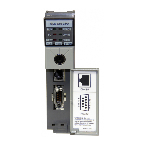
SLC 5/03™, SLC 5/04™, and SLC 5/05™ Modular Processors Installation Procedure Install the Processor Make sure system power is off; then insert the processor into slot 0 of the 1746 chassis. The SLC 500 modular processors must be inserted into the left slot IMPORTANT (slot 0), as shown below. - Page 8 SLC 5/03™, SLC 5/04™, and SLC 5/05™ Modular Processors Power Supply and LED Indicators Indicates the LED is OFF POWER FORCE Indicates the LED is ON DH485 Indicates the LED is FLASHING BATT RS232 Status of LED does not matter...
- Page 9 SLC 5/03™, SLC 5/04™, and SLC 5/05™ Modular Processors 2. Set the communication parameters of the software to match the default parameters of the processor: Channel 0 Configuration Channel 1 Configuration SLC 5/03, 5/04, 5/05 SLC 5/03 SLC 5/04 SLC 5/05...
- Page 10 White Battery Connector Left Side View The SLC 5/03, 5/04, and 5/05 processors have a capacitor that IMPORTANT provides at least 30 minutes of battery back-up while the battery is disconnected. Data in RAM is not lost if the battery is replaced within 30 minutes 4.
-
Page 11: Troubleshooting
SLC 5/03™, SLC 5/04™, and SLC 5/05™ Modular Processors Troubleshooting Before troubleshooting your SLC 500 system, please obtain an SLC 500 Modular Hardware Style User Manual (1747-UM011) from one of the sources listed on page 5. Refer to the chapter on Troubleshooting. - Page 12 SLC 5/03™, SLC 5/04™, and SLC 5/05™ Modular Processors Communication Communication options for the SLC 5/03, 5/04, and 5/05 processors are as follows: • DH485 • RS-232 protocols (DF1 Full-Duplex, DF1 Half-Duplex “master/slave”, DF1 Radio Modem, DH-485, or ASCII) • Data Highway Plus™...
-
Page 13: Battery Handling, Storing, And Transporting (Cat. No. 1747-Ba)
SLC 5/03™, SLC 5/04™, and SLC 5/05™ Modular Processors Memory Back Up The following table shows the memory back up options for the SLC 5/03, 5/04, and 5/05 processors. Flash EPROMs (Flash Erasable Programmable Read Only Memory) combine the versatility of EEPROMs (Electrically-Erasable Programmable Read Only Memory) with the security of UVPROMs (UV-Erasable PROM). -
Page 14: Publication 1747-In009C-Mu-P - December
SLC 5/03™, SLC 5/04™, and SLC 5/05™ Modular Processors Shipment of depleted batteries for disposal may be subject to specific regulation of the countries involved or to regulations endorsed by those countries, such as the IATA Restricted Articles Regulations of the International Air Transport Association, Geneva, Switzerland. - Page 15 Notice d’installation Section en français Processeurs modulaires SLC 5/03™, SLC 5/04™ et SLC 5/05™ (Références 1747-L531 1747-L532, 1747-L541, 1747-L542, 1747-L543, 1747-L551, 1747-L552, 1747-L553, 1747-L542P, 1747-L543P, 1747-L553P) Contenu…..................page Informations importantes destinées à l’utilisateur ......16 Complément d’informations .............. 17 Outils et équipement requis .............. 18 Consignes de sécurité................
-
Page 16: Informations Importantes Destinées À L'utilisateur
Les illustrations, schémas et exemples de programmes contenus dans ce manuel sont présentés à titre indicatif seulement. En raison du nombre important de variables et d’impératifs associés à chaque installation, la société Allen-Bradley ne saurait être tenue pour responsable ni être redevable (y compris en matière de propriété intellectuelle) des suites d’utilisation réelle basée sur les exemples et schémas présentés dans ce manuel. -
Page 17: Complément D'informations
Complément d’informations Pour Voir à ce document Référence Une description détaillée de l’installation et SLC 500 Modular hardware 1747-UM011C de l’utilisation de votre système SLC 500 Style Installation and modulaire. Operation Manual (disponible en anglais uniquement) Un manuel de référence comportant des SLC 500 Instrument Set 1747-RM001C informations sur les données du fichier... -
Page 18: Outils Et Équipement Requis
Outils et équipement requis • un tournevis plat de taille moyenne • un équipement de programmation • un câble 1747-CP3 ou une interface réseau appropriée Interface réseau SLC 5/03 SLC 5/04 SLC 5/05 1747-PIC 1747-CP3 1747-KTX, -PKTX 1747-PCMK 10Base-T EtherNet câble 1784-CP14 requis... -
Page 19: Procédure D'installation
Procédure d’installation Installation du processeur Assurez-vous que l’alimentation est hors tension, puis insérez le processeur dans l’emplacement 0 du châssis 1746. Les processeurs modulaires SLC 500™ doivent être insérés dans IMPORTANT l’emplacement de gauche (emplacement 0), comme illustré ci-dessous. Retirez la bande de protection après avoir installé le processeur. Alimentation Loquet de verrouillage du... - Page 20 Voyants Indique que le voyant est éteint. POWER FORCE Indique que le voyant est allumé. DH485 Indique que le voyant clignote. BATT RS232 L’état du voyant n’a pas d’importance. SLC 5/03 FORCE FORCE POWER POWER ENET BATT RS232 BATT RS232...
- Page 21 2. Définissez les paramètres de communication du logiciel en fonction des paramètres par défaut du processeur : Configuration du canal 0 Configuration du canal 1 SLC 5/03, 5/04, 5/05 SLC 5/03 SLC 5/04 SLC 5/05 DF1 Full-Duplex : DH-485 : DH+™...
- Page 22 Connecteur de la pile Vue latérale gauche Les processeurs SLC 5/03, SLC 5/04 et SLC 5/05 sont équipés d’un IMPORTANT condensateur qui assure au moins 30 minutes de sauvegarde lorsque la pile est déconnectée. Les données contenues dans la RAM ne sont pas perdues si la pile est remplacée dans cet intervalle de 30 minutes.
-
Page 23: Dépannage
Exécution de bit (XIC) 0,44 µs 0,37 µs Logiciel de SLC 5/03 et SLC 5/04 : RSLogix 500™, PLC-500 SérieA.I.™ programmation SLC 5/05 : RSLogix 500™ (1) Les durées de scrutation sont généralement calculées pour un programme de logique à relais 1Ko, composé... - Page 24 Communication Les options de communication des processeurs SLC 5/03, SLC 5/04 et SLC 5/05 sont les suivantes : • DH-485 • Protocoles RS-232 (DF1 Full-Duplex, DF1 Half–Duplex “maître/esclave”, DF1 Radio Modem, DH-485 ou ASCII) • Data Highway Plus™ (carte 1785-KA5P requise pour les processeurs SLC 5/03 et SLC 5/05) •...
-
Page 25: Manipulation, Stockage Et Transport Des Piles (Réf. 1747-Ba)
Le tableau suivant indique les options de sauvegarde de la mémoire pour les processeurs SLC 5/03, SLC 5/04 et SLC 5/05. Les EPROM flash (mémoire flash morte effaçable et programmable) associent la souplesse des EEPROM à la sécurité des UVPROM. Option de SLC 5/03 SLC 5/04 SLC 5/05 sauvegarde de... -
Page 26: Publication 1747-In009C-Mu-P - Décembre
ferrovière, maritime et par avion cargo sous certaines conditions. Le transport par avion passager est interdit. L’expédition de piles déchargées pour mise au rebut est soumise aux règlements spécifiques du pays concerné ou aux règlements avalisés par lesdits pays, tels que les réglementations d’articles restrictifs de l’IATA (International Air Transport Association), Genève. - Page 27 Installationsanleitung Deutscher Abschnitt Modulare Prozessoren SLC 5/03™, SLC 5/04™ und SLC 5/05™ (Bestellnummern 1747-L531, 1747-L532, 1747-L541, 1747-L542, 1747-L543, 1747-L551, 1747-L552, 1747-L553, 1747-L542P, 1747-L543P, 1747-L553P) Inhalt......................Seite Wichtige Hinweise für den Anwender ............28 Weitere Informationen .................. 29 Erforderliche Werkzeuge und Geräte ............30 Sicherheitshinweise ..................
-
Page 28: Wichtige Hinweise Für Den Anwender
Wichtige Hinweise für den Anwender Aufgrund der vielfältigen Einsatzmöglichkeiten der in dieser Publikation beschriebenen Produkte müssen die für die Anwendung und den Einsatz dieses Geräts verantwortlichen Personen sicherstellen, dass jede Anwendung bzw. jeder Einsatz alle Leistungs- und Sicherheitsanforderungen, einschließlich sämtlicher anwendbaren Gesetze, Vorschriften, Bestimmungen und Normen erfüllt. -
Page 29: Weitere Informationen
Weitere Informationen Thema: Dokumentation: Pub.-Nr. Eine detailliertere Beschreibung zur SLC 500 Modular Hardware Style 1747-UM011C Installation und Verwendung des Installation and Operation Manual modularen SLC 500-Systems Referenzhandbuch mit SLC 500 Instruction Set 1747-RM001C Statusfiledaten, Befehlssatz und Reference Manual Informationen zur Störungssuche Wenn Sie ein Handbuch wünschen, können Sie: •... -
Page 30: Erforderliche Werkzeuge Und Geräte
Erforderliche Werkzeuge und Geräte • mittelgroßer Flachschraubendreher • Programmiergerät • 1747-CP3-Kabel oder entsprechende Netzwerkschnittstelle Netzwerkschnittstelle SLC 5/03 SLC 5/04 SLC 5/05 1747-PIC 1747-CP3 1747-KTX, -PKTX 1747-PCMK 10Base-T EtherNet 1784-CP14-Kabel erforderlich 1784-PCM4-Kabel erforderlich 1784-CP13-Kabel erforderlich 1784-PCM6-Kabel erforderlich Sicherheitshinweise Ein Modul darf niemals bei anliegender Spannung installiert, entfernt ACHTUNG oder verdrahtet werden. -
Page 31: Einbauverfahren
Einbauverfahren Einbau des Prozessors Vergewissern Sie sich, dass die Systemspannung ausgeschaltet ist, und schieben Sie den Prozessor anschließend in Steckplatz 0 des Chassis der Reihe 1746. Die modularen Prozessoren der Reihe SLC 500 müssen, wie unten WICHTIG dargestellt, in den linken Steckplatz (Steckplatz 0) eingeschoben werden. - Page 32 Netzteil und LED-Anzeigen LED AUS POWER FORCE LED LEUCHTET DH485 LED BLINKT BATT RS232 LED-Status ist unbedeutend SLC 5/03 POWER FORCE POWER FORCE ENET BATT RS232 BATT RS232 SLC 5/04 SLC 5/05 Laden der Software Hinweise sind in den Handbüchern der Programmiersoftware enthalten.
- Page 33 2. Die Kommunikationsparameter der Software so einstellen, dass sie mit den Vorgabewerten des Prozessors übereinstimmen: Konfiguration : Kanal 0 Konfiguration: Kanal 1 SLC 5/03, 5/04, 5/05 SLC 5/03 SLC 5/04 SLC 5/05 DF1-Vollduplex: DH-485: DH+™: Ethernet • kein Handshaking • 19,2 kBaud •...
- Page 34 White Batterieanschluss linke Seitenansicht Die Prozessoren SLC 5/03, SLC 5/04 und SLC 5/05 sind mit einem WICHTIG Kondensator ausgestattet, der ein Batterie-Backup für mindestens 30 Minuten gewährleistet, während die Batterie nicht angeschlossen ist. Die Daten im RAM-Speicher gehen somit nicht verloren, wenn die Batterie innerhalb von 30 Minuten ausgewechselt wird.
-
Page 35: Störungssuche
0,44 µs 0,37 µs Programmiersoftware SLC 5/03 und SLC 5/04: RSLogix 500™, PLC-500 A.I. Series™ SLC 5/05: RSLogix 500™ (1) Die Abfragezeiten beziehen sich generell auf ein Kontaktplanprogramm (1K), das aus einfacher Strompfadlogik und Kommunikationsbefehlen besteht. Die tatsächlichen Abfragezeiten hängen von der Programmgröße, den verwendeten Befehlen und dem Kommunikationsprotokoll ab. - Page 36 Kommunikation Für die Prozessoren SLC 5/03, SLC 5/04 und SLC 5/05 stehen die folgenden Kommunikationsoptionen zur Verfügung: • DH-485 • RS-232-Protokolle (DF1-Vollduplex, DF1-Halbduplex „Master/Slave“, DF1-Funkmodem, DH-485 oder ASCII) • Data Highway Plus™ (für die Prozessoren SLC 5/03 und SLC 5/05 ist ein 1785-KA5P erforderlich) •...
-
Page 37: Handhabung, Lagerung Und Transport Der Batterie (Best.-Nr. 1747-Ba)
Speicher-Backup Die für die Prozessoren SLC 5/03, SLC 5/04 und SLC 5/05 lieferbaren Speicher-Backup- Option sind in der folgenden Tabelle zusammengefasst. Ein Flash-EPROM-Speicher (Flash Erasable Programmable Read Only Memory) kombiniert die Flexibilität des EEPROM-Speichers mit der Sicherheit des UVPROM-Speichers. Speicher-... - Page 38 Ausnahme können Lithiumbatterien per Kraftfahrzeug, Bahn, Frachtschiff und Frachtflugzeug transportiert werden, vorausgesetzt, dass bestimmte Bedingungen erfüllt werden. Der Transport per Passagierflugzeug ist nicht gestattet. Der Versand von verbrauchten Batterien unterliegt den jeweiligen Bestimmungen des Landes oder den Bestimmungen des Internationalen Lufttransportverbands in Genf (IATA-Regelung bezüglich des Versands von Gefahrengütern).
- Page 39 Istruzioni per l’installazione Sezione in Italiano Processori modulari SLC 5/03™ SLC 5/04™ e SLC 5/05™ (Numeri di catalogo 1747-L531, 1747-L532, 1747-L541, 1747-L542, 1747-L543, 1747-L551, 1747-L552, 1747-L553, 1747-L542P, 1747-L543P, 1747-L553P All’interno…................pagina Informazioni importanti per l’utente..........40 Per ulteriori informazioni ..............41 Strumenti ed apparecchiature necessari ..........
-
Page 40: Informazioni Importanti Per L'utente
Le illustrazioni, gli schemi, i programmi esemplificativi e gli esempi di configurazioni di questo manuale sono intesi esclusivamente ad illustrare il testo. A causa dei numerosi requisiti e variabili propri di ciascuna installazione, la Allen-Bradley declina ogni responsabilità (compresa la responsabilità per la proprietà intellettuale) per l’uso dei prodotti basato sulle applicazioni illustrate in questa pubblicazione. -
Page 41: Per Ulteriori Informazioni
Per ulteriori informazioni Per: Fare riferimento N. pub. alla seguente pubblicazione informazioni più dettagliate sull’installazione Sistema modulare 1747-UM011 e l’utilizzo del sistema modulare SLC 500. SLC 500 - Manuale dell’utente un manuale di riferimento contenente Set di istruzioni per 1747-RM001 informazioni sui dati del file di stato, sul set di SLC 500 - Manuale di istruzioni e sull’individuazione dei guasti. -
Page 42: Strumenti Ed Apparecchiature Necessari
Strumenti ed apparecchiature necessari • cacciavite a taglio medio • apparecchiatura di programmazione • cavo 1747-CP3 o interfaccia di rete appropriata Interfaccia di rete SLC 5/03 SLC 5/04 SLC 5/05 1747-PIC 1747-CP3 1747-KTX, -PKTX 1747-PCMK 10Base-T EtherNet richiede il cavo 1784-CP14... -
Page 43: Procedura Di Installazione
Procedura di installazione Installazione del processore Assicurarsi che il sistema non sia alimentato, quindi inserire il processore nello slot 0 dello chassis 1746. Il processore modulare SLC 500™ deve essere inserito nello slot di IMPORTANTE sinistra (slot 0), come illustrato nella seguente figura. Una volta installato il processore, rimuovere la fascetta protettiva. - Page 44 Indica che il LED è SPENTO POWER FORCE Indica che il LED è ACCESO. DH485 Indica che il LED è LAMPEGGIANTE. BATT RS232 Lo stato del LED non ha importanza SLC 5/03 POWER FORCE POWER FORCE ENET BATT RS232 BATT...
- Page 45 2. Impostare i parametri di comunicazione del software in modo che corrispondano ai parametri predefiniti del processore: Configurazione Canale 0 Configurazione Canale 1 SLC 5/03, 5/04, 5/05 SLC 5/03 SLC 5/04 SLC 5/05 DF1 Full-Duplex: DH-485: DH+™: Ethernet • senza handshaking •...
- Page 46 White Connettore batteria Vista laterale sinistra I processori SLC 5/03, 5/04 e 5/05 hanno un condensatore che IMPORTANTE fornisce almeno 30 minuti di autonomia mentre la batteria è scollegata. Se la batteria viene sostituita entro 30 minuti i dati nella RAM non vengono persi.
-
Page 47: Ricerca Guasti
Tale manuale contiene spiegazioni ed esempi sull’intero set di istruzioni e su tutte le parole e i bit di stato, nonché su tutti i codici di errore possibili individuati nella parola di stato S:6. Caratteristiche tecniche Caratteristiche tecniche di funzionamento Specifiche del 1747- SLC 5/03 SLC 5/04 SLC 5/05 L531 L532... - Page 48 Comunicazione Le opzioni di comunicazione per i processori SLC 5/03, 5/04 e 5/05 sono le seguenti: • DH-485 • Protocolli RS-232 (DF1 Full-Duplex, DF1 Half-Duplex “master/slave”, DF1 Radio Modem, DH-485 o ASCII) • Data Highway Plus™ (È richiesto un 1785-KA5P per i processori SLC 5/03 e SLC 5/05.) •...
-
Page 49: Utilizzo, Stoccaggio E Trasporto Della Batteria (N°. Cat. 1747-Ba)
Back Up della memoria La seguente tabella elenca le opzioni di back up della memoria dei processori SLC 5/03, 5/04 e 5/05. Le EPROM flash (Flash Erasable Programmable Read Only Memory) combinano la versatilità delle EEPROM (Electrically-Erasable Programmable Read Only Memory) con la sicurezza delle UVPROM (UV-Erasable PROM). - Page 50 Restricted Articles Regulations dello IATA (International Air Transport Association), Ginevra, Svizzera. Le normative per il trasporto delle batterie al litio vengono IMPORTANTE periodicamente aggiornate. Le batterie al litio non devono essere bruciate né gettate nei comuni ATTENZIONE raccoglitori di immondizia, in quanto potrebbero esplodere o spaccarsi.
- Page 51 Instrucciones de instalación Sección en español Procesadores modulares SLC 5/03™, SLC 5/04™ y SLC 5/05™ (Números de catálogo 1747-L531, 1747-L532, 1747-L541, 1747-L542, 1747-L543, 1747-L551, 1747-L552, 1747-L553 1747-L542P, 1747-L543P, 1747-L553P) Contenido… ..................... página Información importante para el usuario ..............52 Para obtener más información..................53 Herramientas y equipo necesarios ................
-
Page 52: Información Importante Para El Usuario
La publicación SGI-1.1 de Allen-Bradley, Safety Guidelines for the Application, Installation, and Maintenance of Solid State Control (disponible en la oficina local de Allen-Bradley), describe algunas diferencias importantes entre equipos transistorizados y dispositivos electromecánicos, las cuales deben tomarse en consideración al usar productos tales como los descritos en esta publicación. -
Page 53: Para Obtener Más Información
Para obtener más información Para Consulte este documento Nº de publicación Obtener una descripción más detallada de Manual del usuario del 1747-UM011C cómo instalar y usar el sistema modular hardware estilo modular SLC 500. SLC 500 Obtener un manual de referencia que Manual del referencia del 1747-RM001C contenga información sobre los datos de... -
Page 54: Herramientas Y Equipo Necesarios
Herramientas y equipo necesarios • destornillador de hoja mediana • equipo de programación • cable 1747-CP3 o interface de cable adecuada Interface de red SLC 5/03 SLC 5/04 SLC 5/05 1747-PIC 1747-CP3 1747-KTX, -PKTX 1747-PCMK 10Base-T EtherNet requiere un cable 1784-CP14... -
Page 55: Procedimiento De Instalación
Procedimiento de instalación Instalación del procesador Asegúrese de que la alimentación eléctrica del sistema esté deconectada; luego inserte el procesador en la ranura 0 del chasis 1746. Los procesadores modulares SLC 500™ deben insertarse en la ranura IMPORTANTE izquierda (ranura 0), como se muestra a continuación. Adicionalmente, retire la cubierta protectora después de instalar el procesador. - Page 56 Fuente de alimentacion electrica e indicadores LED Indica que el LED esta APAGADO. POWER FORCE Indica que el LED esta ILUMINADO DH485 Indica que el LED PARPADEA. BATT RS232 El estado del LED no importa. SLC 5/03 POWER FORCE POWER FORCE ENET BATT RS232 BATT RS232...
- Page 57 2. Establezca los parámetros de comunicación del software a los mismos valores que los parámetros predeterminados del procesador: Configuración de canal 0 Configuración de canal 1 SLC 5/03, 5/04, 5/05 SLC 5/03 SLC 5/04 SLC 5/05 DF1 Full-Duplex: DH-485: DH+™: Ethernet •...
- Page 58 Conector de la bateria Vista del lado izquierdo Los procesadores SLC 5/03, 5/04 y 5/05 tienen un capacitor que IMPORTANTE proporciona por lo menos 30 minutos de seguridad de batería de respaldo mientras la batería está desconectada. Los datos en la RAM no se pierden si la batería se reemplaza antes de los 30 minutos.
-
Page 59: Localización Y Corrección De Fallos
0.44 µs 0.37 µs Software de SLC 5/03 y SLC 5/04: RSLogix 500™, PLC-500 A.I. Series™ programación SLC 5/05: RSLogix 500™ (1) Los tiempos de escan son tipicos para un programa de logica de escalera de 1 k que consiste en una logica de escalera simple y servicio de comunicacion. - Page 60 500 mA para el procesador SLC 5/03 1.0 A para los procesadores SLC 5/04 y 5/05 Fuente de alimentación cargando a 24 VCC 175 mA para el procesador SLC 5/03 0 mA para el procesador SLC 5/04 0 mA para el procesador SLC 5/05 Tiempo de retención del escán de...
-
Page 61: Manipulación, Almacenamiento Y Transporte De La Batería (Cat. No. 1747-Ba)
La siguiente tabla muestra las opciones de copia de seguridad (backup) de memoria para los procesadores SLC 5/03, 5/04 y 5/05. Flash EPROM (Memoria de solo lectura programable y borrable Flash) combina la versatilidad de EEPROM con la seguridad de UVPROM. - Page 62 (DOT) en el Código de reglamentos federales, CFR49, “Transporte”. Una excepción a este reglamento, DOT - E7052, cubre el transporte de ciertos materiales peligrosos clasificados como sólidos inflamables. Esta excepción autoriza el transporte de baterías de litio en vehículos motorizados, vagones de carga, barcos de carga y aviones de carga solamente, siempre y cuando se cumplan ciertas condiciones.
- Page 63 Instruções de Instalação Seção em português Controladores de Estrutura Modular SLC 5/03™, SLC 5/04™ e SLC 5/05™ (Códigos de Catálogo 1747-L531, 1747-L532, 1747-L541, 1747-L542, 1747-L543, 1747-L551, 1747-L552, 1747-L553, 1747-L542P, 1747-L543P, 1747-L553P) Índice… ....................página Informações Importantes para o Usuário ............64 Para Obter Mais Informações................
-
Page 64: Informações Importantes Para O Usuário
As ilustrações, gráficos, amostras de programas e exemplos de layouts exibidos neste manual foram feitos exclusivamente para servirem como exemplos. Como existem muitas variáveis e requisitos associados a qualquer instalação específica, a Allen-Bradley não assume nenhuma responsabilidade ou obrigação (incluindo a obrigação de propriedade intelectual) pelo uso atual, com base nos exemplos exibidos nesta publicação. -
Page 65: Para Obter Mais Informações
Para Obter Mais Informações Para Consulte este da Publicação Documento Uma descrição mais detalhada sobre a Manual do Usuário do 1747-UM011C instalação e utilização do sistema modular SLC 500 Modular SLC 500 Hardware Style Um manual de referência que contenha Manual de Referência de 1747-RM001C dados do arquivo de status, conjunto de... -
Page 66: Ferramentas E Equipamentos Necessários
Ferramentas e Equipamentos Necessários • Chave de fenda média • Equipamento de programação • Cabo 1747-CP3 ou interface de rede apropriada Controlador SLC 5/03 SLC 5/04 SLC 5/05 1747-PIC 1747-CP3 1747-KTX, -PKTX 1747-PCMK 10Base-T EtherNet requer cabo 1784-CP14 requer cabo 1784-PCM4... -
Page 67: Procedimento De Instalação
Procedimento de Instalação Instale o Controlador Certifique-se de que a alimentação do sistema esteja desligada; a seguir, instale o controlador no slot 0 do chassi 1746. Os controladores de estrutura modular SLC 500 devem ser inseridos no IMPORTANTE slot esquerdo (slot 0), como exibido abaixo. Além disso, remova o adesivo protetor após instalar o controlador. - Page 68 Indica que o LED está DESLIGADO. POWER FORCE Indica que o LED está LIGADO. DH485 Indica que o LED está PISCANDO BATT RS232 O status do LED não importa. SLC 5/03 POWER FORCE POWER FORCE ENET BATT RS232 BATT RS232...
- Page 69 2. Defina os parâmetros de comunicação do software para corresponder aos parâmetros default do controlador: Configuração do Canal 0 Configuração do Canal 1 SLC 5/03, 5/04, 5/05 SLC 5/03 SLC 5/04 SLC 5/05 DF1 Full-Duplex: DH-485: DH+™: Ethernet • sem handshaking •...
- Page 70 Conector da Bateria Vista Lateral Esquerda Os controladores SLC 5/03, 5/04 e 5/05 têm um capacitor IMPORTANTE que fornece pelo menos 30 minutos de alimentação reserva com a bateria desligada. Os dados da memória RAM não serão perdidos caso a bateria seja substituída em menos de 30 minutos.
-
Page 71: Localização De Falhas
Também contém explicações para todos os códigos de falhas possíveis encontrados na palavra de status S:6. Especificações Especificações Operacionais Especificação do 1747- SLC 5/03 SLC 5/04 SLC 5/05 L531 L532 L541... - Page 72 Comunicação As opções de comunicação dos controladores SLC 5/03, 5/04 e 5/05 são as seguintes: • DH-485 • Protocolos RS-232 (DF1 Full-Duplex, DF1 Half Duplex “mestre/escravo”, Rádio Modem DF1, DH-485 ou ASCII) • Data Highway Plus™ (É necessário haver um 1785-KA5P para os controladores SLC 5/03 e SLC 5/05) •...
-
Page 73: Manuseio, Armazenamento E Transporte Da Bateria (Cód. Cat. 1747-Ba)
Backup de Memória Na tabela a seguir são exibidas as opções de backup de memória dos controladores SLC 5/03, 5/04 e 5/05. As EPROMs instantâneas (“Flash Erasable Programmable Read Only Memory”, Memória Exclusiva de Leitura Programável e Apagável Instantânea) combinam a versatilidade das EEPROMS com a segurança das UVPROMS. - Page 74 Transporte Uma ou Duas Baterias - Até duas baterias podem ser enviadas nos Estados Unidos, sem restrição. As normas sobre a remessa para outros países podem ser diferentes. Três ou Mais Baterias - Os procedimentos para o transporte de três ou mais baterias juntas nos Estados Unidos são especificados pelo Departamento de Transportes (DOT) no Código das Normas Federais, CFR49, em “Transporte”.
- Page 75 Publication 1747-IN009C-MU-P - December 2002...
- Page 76 Publication 1747-IN009C-MU-P - December 2002 PN 40072-090-01(3) Supersedes Publication 1747-IN009B-ML-P - February 2002 Copyright © 2002 Rockwell Automation. All rights reserved. Printed in USA...
Need help?
Do you have a question about the SLC 5/03 and is the answer not in the manual?
Questions and answers