Table of Contents
Advertisement
Quick Links
Advertisement
Table of Contents

Related Manuals for Allen-Bradley PLC–5 MAP/OSI


Summary of Contents for Allen-Bradley PLC–5 MAP/OSI
- Page 1 PLC–5 MAP/OSI Software (Cat. No. 1785-OSI) User Manual AB Parts...
-
Page 2: Table Of Contents
Table of Contents Preface ........Manual Contents . - Page 3 Table of Contents Reading and Writing Data (Using the SET Command) ..4 18 Additional and Advanced Programming Techniques ..Chapter Objectives ........Sending Unsolicited Variable Information (The UINFO Command) Sending Unsolicited Status Information (The USTAT Command) .
- Page 4 Table of Contents OSI Layer Management ......
-
Page 5: Preface
Preface Allen-Bradley PLC-5 MAP/OSI Software (Cat. No. 1785-OSI) Preface Manual Contents This manual provides information on the Allen–Bradley PLC–5 MAP/OSI Software (cat. no. 1785–OSI) and the PLC–5 MAP/OSI Coprocessor (1785–O5G/B). It contains information on the following topics: For this type of information:... -
Page 6: What You Should Receive
Catalog Number: PLC-5 Controllers 1785-L40L/B, -L40B/B, -L60L/B, -L60B/B, -L30B/A, -L20B/A, -L11B/A. Contact your local Allen-Bradley distributor or sales office for a current list of compatible controllers. PLC-5 Programming Software 6200-PLC5, version 4.3 or higher PLC-5 802.4 MAP/OSI Broadband Modem or 1785-O5A, B, C (broadband) or PLC-5 802.4 MAP/OSI Carrierband Modem... - Page 7 Allen-Bradley PLC-5 MAP/OSI Software (Cat. No. 1785-OSI) Figure P.1 You Must Have This Equipment Installed Before Using the OSI Software Into an Allen-Bradley 1771 I/O Chassis series B, install: - the PLC-5 controller - the OSI coprocessor - the P7 power supply...
-
Page 8: Related Publications
Preface Allen-Bradley PLC-5 MAP/OSI Software (Cat. No. 1785-OSI) Related Publications Refer to the following table for information on where to read more about Allen–Bradley MAP/OSI products: Product: Refer to this publication for installation/usage instructions: PLC-5 802.4 MAP/OSI Coprocessor 1785-2.23 PLC-5 802.4 MAP/OSI Broadband Modem 1785-2.12... -
Page 9: Overview Of The Map Communication Environment
Chapter Overview of the MAP Communication Environment Chapter Objectives This chapter introduces you to MAP communication and shows how it relates to your OSI coprocessor. This chapter covers: Open Systems Interconnect (OSI) Manufacturing Automation Protocol (MAP) Manufacturing Message Specification (MMS) the MMS Modeling Concept MAP communications and your OSI coprocessor The following sections contain general overviews of these subjects and are... - Page 10 ‘‘fit” in the seven layer model the same way, those two devices will be able to communicate (figure 1.2). Figure 1.2 Different Vendors' Devices Can Communicate on OSI Networks Allen-Bradley OSI interface PLC Controller with OSI protocol...
-
Page 11: Manufacturing Automation Protocol (Map) 1
Chapter 1 Overview of the MAP Communication Environment Each node on an OSI network is equipped with a layer mechanism that incorporates the ‘‘rules” of the OSI standard. Each layer is able to ‘‘talk” with only its counterpart within the node sending/receiving the data (figure 1.3). -
Page 12: Manufacturing Message Specification
Chapter 1 Overview of the MAP Communication Environment Figure 1.4 The Layers 7 and 1 Are Most Distinct To Your Application Application Program Layer 7 is where your application program first interacts Application with the MAP protocol for transmission onto the network. Presentation Session Transport... -
Page 13: The Mms Modeling Concept 1
Chapter 1 Overview of the MAP Communication Environment Definition). For a complete listing of the MMS services supported by your OSI coprocessor, refer to Chapter 3 of this manual. The MMS Modeling Concept The dominant aspect of MMS is the concept of modeling. MMS defines models that describe the way in which resources are made available and the way in which these resources are accessed. - Page 14 Chapter 1 Overview of the MAP Communication Environment Figure 1.7 Vendors Must Map Their Devices to the VMD Model Device Model Mapping a device to the VMD establishes it as a virtual device on the network. The mapping concept. I - 12412 This mapping of a device to the VMD model establishes a device as a virtual device on the MAP network, allowing it to be accessed by other virtual devices through the use of MMS services.
- Page 15 Chapter 1 Overview of the MAP Communication Environment Figure 1.8 Abstract Object Models are Part of the VMD Model OSI Network abstract object models Resources The OSI coprocessor I - 12413 The models define abstract objects which are part of the VMD. An application program calls on the MMS services associated with a particular object to perform operations on that object.
- Page 16 Chapter 1 Overview of the MAP Communication Environment merely a grouping of domains within a system. Therefore, within the OSI coprocessor, the single program invocation object is made up of a single domain object. Variable Objects Implemented by the OSI Coprocessor Your OSI coprocessor implements the following types of variable objects: Variable Object: Description:...
- Page 17 Chapter 1 Overview of the MAP Communication Environment Figure 1.9 An MMS Server Makes Resources Available to an MMS Client MMS Client An MMS client device accesses resources in the server device using MMS services. OSI Network MMS Server An MMS server device makes resources available for the client to use.
-
Page 18: Implementing Mms
Chapter 1 Overview of the MAP Communication Environment Figure 1.10 An Allen-Bradley PLC Controller as an MMS Server MMS Client An MMS client requests resources from the PLC-5 controller. Resources OSI Network The OSI interface (the coprocessor and the modem) makes PLC-5... -
Page 19: The Plc-5 802.4 Map/Osi Coprocessor
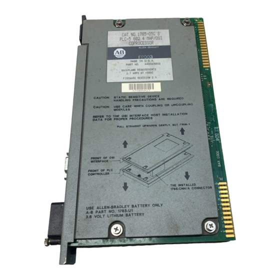
Chapter The PLC-5 802.4 MAP/OSI Coprocessor Chapter Objectives This chapter contains information on using the OSI coprocessor (cat. no. 1785–O5G). It covers the following topics: introduction to the OSI coprocessor non–volatile memory and the lithium battery the LEDs the switches This chapter does not cover installation instructions. - Page 20 The coprocessor is only half of the controller’s connection to the network, you also need a modem. The type of modem depends upon the type of network you are using: For a: You need an Allen-Bradley: Catalog Number: broadband network PLC-5 802.4 MAP/OSI...
- Page 21 Chapter 2 The PLC-5 802.4 MAP/OSI Coprocessor Figure 2.2 Install the OSI Software via the MAP Station Manager MAP Station Manager 1785-OSI Software to OSI Network I - 12417 Refer to the station manager’s user manual (publication 6630–6.5.2) for instructions on installing the software and ‘‘downloading” (system loading) the software to the OSI coprocessor.
-
Page 22: Non-Volatile Memory And The Lithium Battery
Chapter 2 The PLC-5 802.4 MAP/OSI Coprocessor Non-volatile Memory and Non–volatile memory is a portion of memory in the OSI coprocessor the Lithium Battery where the following information is stored: the system load file (the OSI software) the Local Directory Information Base (LDIB) entries other configurable parameters (all MAC–, MMS–, and system–layer parameters, network–layer static routing table, transport–... - Page 23 Chapter 2 The PLC-5 802.4 MAP/OSI Coprocessor Battery Maintenance The life of the lithium battery is related to the time it is in use (when the power to the OSI coprocessor is removed), so it is not possible to predict when you will need to replace it.
-
Page 24: The Leds
Chapter 2 The PLC-5 802.4 MAP/OSI Coprocessor The LEDs The OSI coprocessor has five LEDs on the front panel. At power–up, the LEDs cycle through each of their colors (either red or green) so you can visually inspect them. Each LED has a specific function. Figure 2.4 provides an overview of each LED. -
Page 25: The Switches
Chapter 2 The PLC-5 802.4 MAP/OSI Coprocessor The Switches The OSI coprocessor has a four–position dip switch you can access without removing any covers. The switches are labelled 1, 2, 3, and 4 and are located at the back of the coprocessor. Above the switches you will see a small legend that illustrates the ON and OFF position of the switches (figure 2.5). - Page 26 MAC layer and RS-232 port settings. If no user defaults are parameters when you edit them via stored, Allen-Bradley the Allen-Bradley MAP Station communication defaults are Manager. The coprocessor uses Then the coprocessor: If you select: used.
-
Page 27: Mms And Your Osi Coprocessor
Chapter MMS and Your OSI Coprocessor Chapter Objectives This chapter covers how your OSI coprocessor supports MMS services, it contains the following sections: The Supported MMS Services Mapping MMS Data Types onto PLC–5 Controller Data Files Additional Information on Using Data Types MMS Object Management MMS Security We assume you are already familiar with MMS and programming PLC–5... - Page 28 OSI coprocessor. The information includes the vendor name the OSI coprocessor receives an Identify request from another (``Allen-Bradley Company"), the model name (e.g., PLC-5 MAP/OSI MMS device. Interface) and the revision identifier of the OSI software that changes with each new software update.
- Page 29 Chapter 3 MMS and Your Coprocessor MMS Service: Description: Support: UploadSegment An MMS client uses this service to request that the OSI coprocessor send a Server. The server side of the UploadSegment service is piece of the PLC-5 controller's memory image. This involves reading a block invoked when the request is received.
- Page 30 Chapter 3 MMS and Your Coprocessor MMS Service: Description: Support: Start An MMS client uses this service to put the PLC-5 controller into run or test Server. The server side of the Start service is invoked when mode. With this request, the client can specify an ``execution argument" the request is received.
- Page 31 Chapter 3 MMS and Your Coprocessor MMS Service: Description: Support: DefineNamed This is used by the PLC-5 system, in conjunction with the OSI coprocessor, Client and server. The client side of the DefineNamedVariable Variable to define an MMS named variable. An MMS client can also use this to define service within the OSI coprocessor is invoked by programming a named variable within the coprocessor.
-
Page 32: Mapping Mms Data Types Onto Plc-5 Controller Data Files 3
Chapter 3 MMS and Your Coprocessor Mapping MMS Data Types The MMS specification lists a set of data types, or formats, that your onto PLC-5 Controller Data variables are allowed to take. The data types allowed for your OSI Files coprocessor are: boolean bitstring... -
Page 33: Additional Information On Using Data Types 3
Chapter 3 MMS and Your Coprocessor The sections that follow provide sample mappings of each PLC controller data table category listed above. We use the following conventions in our examples: This: Means: B3:0,n a bit-string of length n starting at bit 0 of the specified word. B3:0/x,n a bit-string of length n starting at bit x (octal) of the specified word. - Page 34 Chapter 3 MMS and Your Coprocessor Signed Word (N) Mappings The following table contains samples of mapping signed word data types. Address: MMS Data Type: N7:0 INTEGER (16 bits) N7:0,8 ARRAY of 8 INTEGERS N7:0/0 BOOLEAN N7:0/3,5 BITSTRING (5 bits) See the section titled Additional Information on Using Data Types, later in this chapter, and Appendix A of this manual for more information on mapping MMS data types onto PLC–5 data files.
- Page 35 Chapter 3 MMS and Your Coprocessor Address: MMS Data Type: T4:15 STRUCTURE of type TIMER T4:3,10 ARRAY of 10 TIMER STRUCTURES T4:1.DN BOOLEAN T4:1.TT BOOLEAN T4:1.EN BOOLEAN T4:0.ACC INTEGER T4:13.PRE INTEGER T4:0.DN,4 ARRAY of 4 BOOLEANS (This specifies 4 done bit members of TIMERS 0 to 3. This also applies to TT and EN members.) T4:0.ACC,50 ARRAY of 50 INTEGERS (This example specifies 50 accumulator members of...
- Page 36 Chapter 3 MMS and Your Coprocessor Address: MMS Data Type: C5:4.CD BOOLEAN C5:1.CU BOOLEAN C5:0.ACC INTEGER C5:13.PRE INTEGER C5:0.DN,4 ARRAY of 4 BOOLEANS (This example specifies 4 done bit members of COUNTERS 0 to 3. This also applies to the other BOOLEAN members.) C5:0.ACC,50 ARRAY of 50 INTEGERS (This example specifies 50 accumulator members of COUNTERS 0 to 49.
- Page 37 Chapter 3 MMS and Your Coprocessor Output Image (O) Mappings The table that follows provides sample mappings of output image data types, where: O:000/x,n is a bit–string of length n starting at bit x (octal) of the specified word. Important: Note that addressing in the Output Image Mapping is in octal. This does not pertain to the ‘‘size”...
- Page 38 Chapter 3 MMS and Your Coprocessor The following table provides sample mappings of block transfer read data types. Address: MMS Data Type: BT9:0 STRUCTURE of type BLOCK TRANSFER BT9:0,10 ARRAY of 10 BLOCK TRANSFER STRUCTURES BT9:0.RW BOOLEAN (applies to all other BOOLEAN members) BT9:0.RW,5 ARRAY of 5 BOOLEANS (applies to all other BOOLEAN members) BT9:0.RLEN...
- Page 39 Chapter 3 MMS and Your Coprocessor See the section titled Additional Information on Using Data Types and Appendix A of this manual for more information on mapping MMS data types onto PLC–5 data files. Status (S) Mappings The following table provides samples of mapping status data types. Address: MMS Data Types: S:10...
- Page 40 Chapter 3 MMS and Your Coprocessor PID Structure (PD) Mappings The following is the format of a PID structure as viewed by MMS: BOOLEAN BOOLEAN BOOLEAN BOOLEAN BOOLEAN BOOLEAN BOOLEAN BOOLEAN BOOLEAN BOOLEAN PVHA BOOLEAN PVLA BOOLEAN DVPA BOOLEAN DVNA BOOLEAN BOOLEAN BOOLEAN...
- Page 41 Chapter 3 MMS and Your Coprocessor Important: Refer to your PLC–5 Programming Reference Manual for descriptions of the individual fields in data type structures. The following table provides samples of mapping PID data types. Address: MMS Data Types: PD10:0 STRUCTURE of type PID PD10:1,2 ARRAY of two PID STRUCTURES PD10:0.PE...
- Page 42 Chapter 3 MMS and Your Coprocessor Address: MMS Data Types: MG9:0 STRUCTURE of tyoe MESSAGE CONTROL MG9:1,3 ARRAY of 3 MESSAGE CONTROL STRUCTURES MG9:0.ER BOOLEAN MG9:0.TO,9 ARRAY of 9 BOOLEANS (applies to all other BOOLEAN members). MG9:0.ERR INTEGER (applies to all other INTEGER members). MG9:0.DLEN,5 ARRAY of 5 INTEGERS (applies to all other INTEGER types).
- Page 43 Chapter 3 MMS and Your Coprocessor The following table provides samples of mapping sequential function chart data types. Address: MMS Data Type: SC13:0 STRUCTURE of type SFC SC13:0,2 ARRAY of 2 SFC STRUCTURES SC13:0.DN BOOLEAN SC13:0.ER,4 ARRAY of 4 BOOLEANS (applies to all other BOOLEAN types) SC13:0.PRE INTEGER (applies to TIM)
-
Page 44: Additional Information On Using Data Types
Chapter 3 MMS and Your Coprocessor Additional Information on The following list contains general information on some of the data types Using Data Types listed in the preceding sections. You can access all integer locations with either 16 or 32 bit sizes in an MMS Type Specification. -
Page 45: Mms Object Management
Chapter 3 MMS and Your Coprocessor - arrays of arrays are never allowed. MMS Object Management This section covers MMS object management operations, including: retaining MMS objects in non–volatile memory saving MMS objects to, and restoring them from, DOS files information on MMS named variables that always exist in the OSI coprocessor Retaining MMS Objects... - Page 46 Chapter 3 MMS and Your Coprocessor remove the power and the battery from the OSI coprocessor, resulting in the loss of non–volatile memory. cause the auto clear function to clear non–volatile memory (see the section titled Switch 3 in Chapter 2 for details of the auto clear function).
- Page 47 Chapter 3 MMS and Your Coprocessor value 1 indicates the switch is ON, and the value 0 indicates the switch is OFF. You can read this variable using MMS services, but you cannot write it. AB Parts 3-21...
-
Page 48: Mms Security
Chapter 3 MMS and Your Coprocessor AB_PLC5_LAST_EDIT_TIME: this named variable is of type generalized time and indicates the last time the user program was edited. This is a time ‘‘marker” that is updated when you: - clear the PLC–5 controller’s memory - insert or remove instructions - create or delete program files - perform set or reset test edits... - Page 49 Chapter 3 MMS and Your Coprocessor DeleteNamedType MMS security acts as a ‘‘master switch” you set either ON or OFF through the MAP Station Manager. With it, you can choose to either give remote applications the access to these 16 services (maximum privilege) or no access to these services (minimum privilege).
- Page 50 Chapter 3 MMS and Your Coprocessor Refer to the Allen–Bradley MAP Station Manager user manual (publication 6630–6.5.2) for instructions on setting MMS Security and setting Privileges. 3-24...
-
Page 51: Basic Programming Techniques
Chapter Basic Programming Techniques Chapter Objectives Use the information contained in this chapter to program your OSI coprocessor. This chapter contains the following sections: Introduction Entering Commands Things You Should Know Before You Program A Quick Reference Guide to the Commands Managing Connections (the OPEN, CLOSE, and ABORT Commands) Defining MMS Named Variables (the DEFVAR Command) Deleting MMS Named Variables (the DELVAR Command) - Page 52 OSI Network You program your OSI Interface here, through 6200 software. Allen-Bradley Station Manager Allen-Bradley T50 Terminal or IBM PC Compatible/DOS Computer I - 12420 Entering Commands You enter the commands and qualifiers through the PLC–5 programming software (cat. no. 6200–PLC5, version 4.3 or higher) running on either an Allen–Bradley T50 industrial terminal (1784–T50) or a personal computer.
- Page 53 Chapter 4 Basic Programming Techniques Figure 4.2 Sample Message Instruction MG9:3 SEND/RECEIVE MESSAGE Control Block MG9:3 I - 12421 The procedure for using the PLC–5 programming software is listed below. You can exit from this procedure at any time by pressing the [ESC] key. Important: We assume you are familiar with programming Allen–Bradley PLC controllers using the PLC–5 programming software.
- Page 54 Chapter 4 Basic Programming Techniques Enter a valid MSG address (for example MG9:30), and press [ENTER]. The following message appears: Press a key to change a parameter or <ENTER> to accept parameters Press [F1], the Command Type option as many times necessary until you see a screen like: MESSAGE INSTRUCTION DATA ENTRY FOR COMMAND BLOCK MG9:30 Communication Command:...
-
Page 55: What You Should Know Before You Program 4
If you are already familiar with these topics, you can skip ahead to the individual command sections later in this chapter. The Allen-Bradley Commands The following table contains the programming software commands you can use to program the OSI coprocessor. The table also shows the related MMS service functions for each command. - Page 56 Chapter 4 Basic Programming Techniques General Rules for Using MMS Named Variables The MMS protocol allows you to associate a name with an address within the node. These associated names are called MMS named variables. It is easier, for example, to remember Paint_station_1 than it is to remember N12:1 (figure 4.3).
- Page 57 Chapter 4 Basic Programming Techniques For example: ”B7:6,10” AB Parts...
-
Page 58: A Quick Reference Guide To The Commands 4
...if the device to which you are connecting only supports 2 outstanding messages, you are a connection limited to 2 on this connection. Even though your Allen-Bradley PLC controller supports up to 5 outstanding messages... OSI Coprocessor I - 12423... - Page 59 Chapter 4 Basic Programming Techniques For detailed information on: Refer to the sections located: OPEN, CLOSE, ABORT, DEFVAR, DELVAR, and later in this chapter UNINFO, USTAT, and MOVE in chapter 5 AB Parts...
- Page 60 Chapter 4 Basic Programming Techniques Quick Reference Guide to the 1785-OSI Commands Command: Can Syntax: Examples: abbreviate to: OPEN 1 character, OPEN <connection> TO <AE_name> open :c16 to 'parts_bin_4' upper or lower Special Note: AE names can be in either single or double quotes. OP :C9 T "PARTS_BIN_14"...
-
Page 61: Managing Connections (The Open, Close And Abort Commands)
Figure 4.5 Establishing a Connection with the OPEN Command Programming terminal Allen-Bradley OSI Coprocessor with 6200 software The OPEN command ... open :C1 to 'xx` OSI Network ...opens a connection with... - Page 62 Chapter 4 Basic Programming Techniques LDIB via the Allen–Bradley MAP Station Manager. Refer to the MAP Station Manager User’s Manual for more information (publication 6630–6.5.2). The OPEN command has the following syntax: OPEN <connection> TO <application entity name> The following table defines each part of the OPEN command line. This: OPEN the command that initiates the connection.
- Page 63 Chapter 4 Basic Programming Techniques Figure 4.6 Terminating a Connection with the CLOSE Command Allen-Bradley OSI Coprocessor Programming terminal with 6200 software The CLOSE command ... close :C4 OSI Network ...terminates connection with a remote node. another vendor's MAP device...
- Page 64 Chapter 4 Basic Programming Techniques c :c1 The ABORT command abruptly terminates the connection between the OSI coprocessor and a remote node on the MAP network. You can abort only the connections that you established from your local PLC–5 controller. If there are problems with a connection, you would use the abort command.
- Page 65 Establishing a Connection to the OSI Coprocessor with :C0 As part of the power-up procedure, a special connection is automatically established from the coprocessor, to the coprocessor. Allen-Bradley OSI Coprocessor OSI Network I - 12426 This connection is always available to the coprocessor operator and allows you to manage your local MMS named variables without having to open or close connections.
-
Page 66: Defining Mms Named Variables (The Defvar Command)
Chapter 4 Basic Programming Techniques Defining MMS Named Within MMS, you must define a variable so that application programs can Variables (The DEFVAR access it. The DEFVAR command defines MMS named variables in a Command) VMD. Refer to the section titled What You Should Know Before You Program, earlier in this chapter, for guidelines on using MMS named variables. -
Page 67: Deleting Mms Named Variables (The Delvar Command)
Chapter 4 Basic Programming Techniques See the section titled Connection Zero, earlier in this chapter for more information on connection zero. Deleting MMS Named Use the DELVAR command to delete MMS named variables. Variables (The DELVAR The DELVAR command has the following syntax: Command) DELVAR <connection><remote_symbol>... -
Page 68: Reading And Writing Data (Using The Set Command)
Chapter 4 Basic Programming Techniques Reading and Writing Data The SET command transfers (reads or writes) an element, a contiguous (Using the SET Command) block of elements, or an MMS structure to or from a node on the MAP network. Keep in mind that the syntax for the SET command to read is different from using it to write. - Page 69 Chapter 4 Basic Programming Techniques the source SET ’STATION_2’ = :C6’STATION_9’ the command the assignment the MMS named variable qualifier the MMS named variable the connection identifier that is the destination followed by the number 6 AB Parts 4-19...
- Page 70 Chapter 4 Basic Programming Techniques Here are more examples of using SET to read: set ’vat_#18’ = :c3’fluids’ SE ”t4:43” = :C78’timer_44’ SET ’plank_50’ = :c6”n7:99” Using the SET Command to Write Data The syntax for using the SET command to write is: SET <destination>...
- Page 71 Chapter 4 Basic Programming Techniques SET :c6’plank_50’ = ”n7:99” Using SET with Connection Zero You can also transfer data within your local PLC–5 controller using the SET command. You use the command in conjunction with connection zero (:C0). The rules apply the same way for reading and writing on connection zero as discussed in the two previous sections.
-
Page 72: Additional And Advanced Programming Techniques
Chapter Additional and Advanced Programming Techniques Chapter Objectives This chapter contains additional programming techniques. In it, we cover the following topics: sending unsolicited variable information (the UINFO command) sending unsolicited status information (the USTAT command) reading and writing data (using the MOVE command) obtaining status on a connection (using CSTAT) specifying the data type of an MMS named variable (using DTYPE) defining scopes of MMS named variables (using DEFVAR) - Page 73 Chapter 5 Addditional and Advanced Programming Techniques Here are examples of using the UINFO command: UINFO ’TEMPERATURE_4’ :C25 ”T4:0.ACC” :C601 The related MMS service for UINFO is InformationReport. AB Parts...
-
Page 74: Sending Unsolicited Status Information (The Ustat Command)
Chapter 5 Additional and Advanced Programming Techniques Sending Unsolicited Status You can send unsolicited status information using the USTAT command Information (The USTAT (this will be the same status as in the MMS Status Response in server mode). This command has the following syntax: Command) USTAT <connection>... - Page 75 Chapter 5 Addditional and Advanced Programming Techniques MOVE TO <destination> FROM <connection><source> You can also switch the placement of the qualifiers within the command line: MOVE FROM <connection><source> TO <destination> The following table defines each part of the MOVE command line. This: MOVE the command that requests the data transfer.
- Page 76 Chapter 5 Additional and Advanced Programming Techniques Here are more examples of using the MOVE command to read: MOVE FROM :C9’PLATFORM_3’ TO ’BAY_44’ m t ”n12:1” f :c34’station_16’ mov fr C:7”n34:2” to ”n12:9” Using the MOVE Command to Write Data The syntax for using MOVE to write data is: MOVE FROM <source>...
- Page 77 Chapter 5 Addditional and Advanced Programming Techniques For example: MOVE FROM ’ROBOT_4’ TO :c18”n4:9” the command the remote address that is the destination a qualifier a qualifier the MMS named variable the connection identifier that is the source followed by the number 18 The important thing to remember about the syntax for using the MOVE command to write is the placement of the source and destination.
-
Page 78: Obtaining Status On A Connection (Using Cstat)
Chapter 5 Additional and Advanced Programming Techniques For example: MOVE FR :C0’MY_VARIABLE’ TO ”B7:6” As noted in the previous section, the placement of :C0 determines weather you are reading or writing, but on connection zero reading and writing data are essentially the same. You are reading/writing to/from the local OSI coprocessor. -
Page 79: Specifying The Data Type Of An Mms Named Variable (Using Dtype)
Chapter 5 Addditional and Advanced Programming Techniques Specifying the Data Type of When you use the DEFVAR command to define an MMS named variable, an MMS Named Variable you are also specifying the data type for which that variable will be used (using DTYPE) (see Chapter 4 for more information on DEFVAR). - Page 80 Chapter 5 Additional and Advanced Programming Techniques If you do not specify the data type, the default data type for the remote address that you have entered is assumed. For example, the following shows how to define the variable painter_6 for the BCD (binary coded decimal) address type D11:7,2: DEFVAR :C1’painter_6’...
- Page 81 Chapter 5 Addditional and Advanced Programming Techniques Figure 5.1 Verifying Another Machine Accepts the Data Type You Want to Use Allen-Bradley OSI Coprocessor You can use the DTYPE parameter your def :c6'ven' t "xxx" dt "f8:0,1" command line... OSI Network ...to...
- Page 82 Chapter 5 Additional and Advanced Programming Techniques named variables with domain scope for other vendor’s devices (if supported by those devices). Defining VMD-specific Scope VMD–specific will probably be the most widely used scope type for MMS named variables in your application and is probably the only one you need to use.
- Page 83 Chapter 5 Addditional and Advanced Programming Techniques The following example shows how to specify AA–specific scope: DEFVAR :C78’/AA/TIMER’ TO ”N7:0” The MMS named variable is TIMER and is in single quotes. By placing /AA/ just before the variable, we are specifying application association scope.
-
Page 84: Deleting Mms Named Variable Of A Particular Scope (Using Delvar)
Chapter 5 Additional and Advanced Programming Techniques Rules for Specifying Domain–specific Scopes When specifying domain scope, keep the following rules in mind: you can abbreviate DOMAIN to one or more characters, upper or lower case a colon must separate DOMAIN (or its abbreviation) and the domain name, with no spaces between them you must specify the domain name the domain name can be up to 32 characters long and can contain the... -
Page 85: Specifying Mms Named Variable Scope Within Set And Move 5
Chapter 5 Addditional and Advanced Programming Techniques The same rules apply for deleting domain–scope variable that apply for defining them. For the rules, see the section titled Rules for Specifying Domain–specific Scopes, earlier in this chapter. Specifying MMS Named Within the SET and the MOVE command lines, you have the opportunity Variable Scope Within SET to specify the scope of an MMS named variable. - Page 86 Chapter 5 Additional and Advanced Programming Techniques SET ’PARTS’ = :C8’/VMD/BOX_1’ The MMS named variable is BOX_1 and is in single quotes. Here, we are specifying VMD-specific scope, with VMD within slash marks (/) and within the single quotes. 5-15...
- Page 87 Chapter 5 Addditional and Advanced Programming Techniques If you do not specify the scope of an MMS named variable, it automatically defaults to VMD–specific scope. With that in mind, we could have accomplished the same result if we had used the above command line as: SET ’PARTS’...
- Page 88 Chapter 5 Additional and Advanced Programming Techniques through 9, an underscore (_), and a dollar sign ($). It cannot start with a numeral. The following example shows how to specify domain–specific scope: set :C100’/DOMAIN:PAINT/LEVEL’ = ’/aa/station_9’ The MMS named variable is LEVEL and is in single quotes. DOMAIN is the scope and PAINT is the domain name.
-
Page 89: Specifying Mms Named Variable Scope Within Uinfo
Chapter 5 Addditional and Advanced Programming Techniques Specifying AA–specific Scope Within the MOVE Command Line This is an example of specifying AA–specific scope: move from :C51’/aa/timer’ t ”N9:0” The MMS named variable is TIMER and is in single quotes. By placing /AA/ just before the variable, we are specifying application association scope. -
Page 90: Mapping Mms Data Types Onto Plc-5/40, -5/60 File Types
Appendix Mapping MMS Data Types onto PLC-5/40, -5/60 File Types Appendix Contents The following table contains the MMS data types and PLC–5/40, –5/60 file types for you to use as a reference when mapping the two types during your application programming. Refer to Chapter 2 for format examples of the PLC Data Table File Types mapped as ‘‘MMS Structures”... - Page 91 Appendix A Mapping MMS Data Types onto PLC-5/40, -5/60 File Types T.ACC D(16) AB Parts...
- Page 92 Appendix A Mapping MMS Data Types onto PLC-5/40, -5/60 File Types MMS Data Types PLC-5 Data Table File Types: Boolean: Bit String: Integer: BCD: Unsigned Floating Visible Octet Integer: Point: String: String: Structure: Counter (C) C.UN C.OV C.DN C.CD C.CU C.PRE D(16) C.ACC...
- Page 93 Appendix A Mapping MMS Data Types onto PLC-5/40, -5/60 File Types MMS Data Types PLC-5 Data Table File Types: Boolean: Bit String: Integer: BCD: Unsigned Floating Visible Octet Integer: Point: String: String: Structure: PD.OLL PD.SPOR PD.INI PD.SP PD.KP PD.KI PD.KD PD.BIAS PD.MAXS PD.MINS...
- Page 94 Appendix A Mapping MMS Data Types onto PLC-5/40, -5/60 File Types MMS Data Types PLC-5 Data Table File Types: Boolean: Bit String: Integer: BCD: Unsigned Floating Visible Octet Integer: Point: String: String: Structure: MG.NR MG.ERR D(16) MG.RLEN D(16) MG.DLEN D(16) MG.DATA D(104) Block Transfer Control (BT)
-
Page 95: Error Codes
Appendix Error Codes Appendix Contents This appendix contains a list of error codes that can be returned to a MSG instruction given to the OSI interface for execution. Decimal: Hex: Description: 0101 The requested command is inappropriate for the state of the connection. 0103 CLOSE (conclude) not supported by remote device. - Page 96 Appendix B Error Codes 013a The local variable is specified with inconsistent attributes. 013b The local variable is not defined to allow the requested access. 013c The local unnamed variable does not exist. Decimal: Hex: Description: 013d The local named variable does not exist. 013e The local named variable has invalid address reference.
- Page 97 Appendix B Error Codes 0171 The specified application reference is invalid at the remote node. 0172 The specified application does not support the desired application context at the remote node. 0178 General object definition problem at remote node. Decimal: Hex: Description: 0179 The object does not exist at the remote node.
- Page 98 The requested variable does not exist at the remote node. 01fa The local node determined that the communication protocol is invalid. This indicates an inter-operability problem -- please contact Allen-Bradley. 01fb The remote node determined that the communication protocol is invalid. This indicates an...
-
Page 99: Pics Part 1: Implementation Information
The following table lists the implementation values for the your OSI Information coprocessor: Implementation Information: Value: Implementation's vendor Name Allen-Bradley Company Implementation's Model Name PLC-5 MAP/OSI Interface Implementation's Revision Identifier (see note 1, below) Machine Name(s) and Version Number(s) PLC-5/40... -
Page 100: Pics Part 2: Service Cbbs
Appendix C PICS Note for PICS Part 1 Note 1: The Revision Identifier will change with each new PLC–5 MAP/OSI Interface Software update and will reflect the version of the software. PICS Part 2: Service CBBs The following is the MMS Service CBB (Conformance Building Block) table, which indicates whether or not the MMS implementation fulfills the server requirements, the client requirements, or both when operating in the abstract syntax (as defined in Part 2 of ISO/IEC 9506, clause 19). - Page 101 Appendix C PICS Service Conformance Building Blocks: Server, Client, or Both: Resume Server Reset Server Kill GetProgramInvocationAttributes Server Read Both Write Both InformationReport Server GetVariableAccessAttributes Server DefineNamedVariable Both DefineScatteredAccess GetScatteredAccessAttributes DeleteVariableAccess Both DefineNamedVariableList Server GetNamedVariableListAttributes Server DeleteNamedVariableList Server DefineNamedType Server GetNamedTypeAttributes Server DeleteNamedType...
-
Page 102: Pics Part 3: Parameter Cbbs
Appendix C PICS Service Conformance Building Blocks: Server, Client, or Both: DeleteEventEnrollment AlterEventEnrollment ReportEventEnrollmentStatus GetEventEnrollmentAttributes AcknowledgeEventNotification AttachToEventCondition EventNotification GetAlarmSummary GetAlarmEnrollmentSummary ReadJournal WriteJournal InitializeJournal CreateJournal DeleteJournal ReportJournalStatus ObtainFile FileOpen FileRead FileClose FileRename FileDelete FileDirectory PICS Part 3: Parameter The following table indicates what MMS Parameter Conformance Building CBBs Blocks are supported for the PLC–5 802.4 MAP/OSI Coprocessor. -
Page 103: Pics Part 4: Local Implementation Values
Appendix C PICS VLIS REAL AKEC PICS Part 4: Local The following table provides the Local Implementation Values for your Implementation Values PLC–5 802.4 MAP/OSI Coprocessor. Description: Value: Range of values for floating point numbers (see Note 1) Supported values of the floating point exponent width Supported values of the floating point format width... - Page 104 Appendix C PICS Load Data Format (see Note 16) Maximum number of Upload State Machines (see Note 17) Notes for PICS Part 4 Note 1: The PLC–5 controller supports all valid normalized single–precision floating point values, as described in IEEE 754. Note 2: All integers in the PLC–5 controller can be accessed as signed integers within the range of –32768 (–(2**15) to 32767 ((2**15)–1) decimal.
- Page 105 Appendix C PICS Processor is in Test mode. Processor is in Program Mode. Description: Number: Currently burning EEPROM. Downloading in process. Test edits enabled. Mode Switch in REMOTE. Forces enabled. Forces present. EEPROM successfully burned. Performing online programming. Processor is in debug mode. User program checksum done.
- Page 106 Appendix C PICS Argument will be ‘‘RUN” at powerup of the PLC–5 OSI Interface. Anytime after powerup, the default Execution Argument will reflect the last (most recent) mode of the PLC–5 processor. The character string form of the Execution Argument parameter is the only form supported. Note 12: The PLC–5 OSI Interface will return various Additional Code values when errors are detected during processing domain management services.
-
Page 107: The Communication Layers' Attributes
Appendix The Communication Layers' Attributes Appendix Contents This appendix provides information on the communication layer attributes associated with your OSI coprocessor. It contains the following sections: Introduction to Attributes Definition of Default Settings Frequently Used Acronyms System–Layer Attributes System–Load Attributes MMS Attributes ACSE (Association Control Service Element)–Layer Attributes Presentation–Layer Attributes... -
Page 108: Definition Of Defaults
Appendix D ATTENTION: The OSI coprocessor is shipped with its attributes pre–set to Allen–Bradley default settings. Some of these should not be changed because it can cause severe communication problems. For the attributes that you can change, you should do so from the Allen–Bradley MAP Station Manager. -
Page 109: System-Layer Attributes
Appendix D System-Layer Attributes The System–Layer attributes control the communication between the OSI coprocessor and the Allen–Bradley MAP Station Manager. System-Layer Description: Parameters: System-Layer Status: Description: Definition of Defaults AB Parts... -
Page 110: System-Load Attributes
Appendix D System-Layer Status: Description: System-Layer Actions: Description: System-Load Attributes The following tables list the System–Load parameters. System-Load Parameters: Description:... -
Page 111: Mms Attributes
Appendix D System-Load Parameters: Description: System-Load Actions: Description: MMS Attributes The following table lists the MMS attributes for the OSI coprocessor. MMS Parameters: Description: MMS Counters: Description: AB Parts... -
Page 112: Acse-Layer Attributes
Appendix D MMS Actions: Description: Important: Important: ACSE-Layer Attributes The ACSE (Association Control Service Element)–Layer attributes are listed in the following tables. ACSE-Layer Parameters: Description: ACSE-Layer Counters: Description:... -
Page 113: Presentation-Layer Attributes
Appendix D Presentation-Layer The following table lists the Presentation–Layer attributes for your OSI Attributes coprocessor. Presentation-Layer Parameters: Description: Presentation-Layer Counters: Description: Session-Layer Attributes The following table lists the Session–Layer Attributes for the OSI coprocessor. Session-Layer Parameters: Description: Session-Layer Counters: Description: AB Parts... -
Page 114: Transport-Layer Attributes
Appendix D Session-Layer Counters: Description: Transport-Layer Attributes The following table lists the Transport–Layer attributes for the OSI coprocessor. Transport-Layer Parameters: Description:... - Page 115 Appendix D Transport-Layer Parameters: Description: disabled enabled Transport-Layer Counters: Description: AB Parts...
-
Page 116: Network-Layer Attributes
Appendix D Transport-Layer Counters: Description: Network-Layer Attributes The following table lists the Network–Layer attributes for the OSI coprocessor. Network-Layer Parameters: Description: disabled enabled. Network-Layer Counters: Description: D-10... -
Page 117: Llc-Layer Counters
Appendix D Network-Layer Counters: Description: LLC-Layer Counters The following table lists the LLC (Logical Link Control)–Layer counters for the OSI coprocessor. LLC-Layer Counters: Description: AB Parts D-11... -
Page 118: Mac Layer Attributes
Appendix D MAC Layer Attributes The MAC (Media Access Control)–Layer attributes control the way in which information is sent out onto the network. The OSI coprocessor’s MAC–Layer attributes are listed in the following tables, along with a brief description and the default settings for each. ATTENTION: Your OSI coprocessor is shipped with its MAC–Layer parameters pre–set to their Allen–Bradley default values. - Page 119 Appendix D MAC Layer Description: Parameter: MAC-Layer Counters: Description: MAC-Layer Actions: Description: AB Parts D-13...
-
Page 120: Port Parameters
Appendix D RS-232 Port Parameters The following table lists the RS–232 Port parameters for your OSI coprocessor RS-232 Parameters: Possible Values: Default Value: D-14... - Page 121 Appendix OSI Layer Management Appendix Contents Each of the OSI layers has a layer management entity (LME) that: is responsible for specific layer management information can pass that management information to the Network Management Agent (NMA) via each layer’s attributes (see Appendix D for details on layer attributes).
- Page 122 Appendix E ACSE Attribute: Description: Attrid Settabl value or range: Events The ACSE LME issues an event when any of the counter attributes listed in the table above reaches its corresponding threshold. Actions There are no actions defined for ACSE.
- Page 123 Appendix E Presentation Attributes The following table lists the Presentation Attributes. Attribute: Description: Attrid Settable: Set value or range: Events The Presentation LME issues an event when any of the counter attributes listed in the table above reaches its corresponding threshold. Actions AB Parts There are no actions defined for Presentation.
- Page 124 Appendix E Session Attributes The following table lists the Session Attributes. Attribute: Description: Attrid Settable: Set value or range: Events The Session LME issues an event when any of the counter attributes listed in the table above reaches its corresponding threshold. Actions There are no actions defined for Session.
- Page 125 Appendix E Transport Attributes The following table lists the Transport Attributes. Attribute: Description: Attrid Settable: Set value or range: AB Parts...
- Page 126 Appendix E Attribute: Description: Attrid Settable: Set value or range: Events The Transport LME issues an event when any of the counter attributes listed in the table above reaches its corresponding threshold. Actions There are no actions defined for Transport.
- Page 127 Appendix E Network Attributes The following lists the Network Attributes. Attribute: Description: Attrid Settable: Set value or range: AB Parts...
- Page 128 Appendix E Events The Network LME issues an event when any of the counter attributes listed in the previous table reaches its corresponding threshold. Actions There are currently two ACTIONS supported by the Network LME. Add routing table entry(s)-This action adds one or more entries to the routing table.
- Page 129 Appendix E MAC Attributes The following table lists the MAC Attributes. Attribute: Description: Attrid Settable: Set value or range: who follows AB Parts...
- Page 130 Appendix E Attribute: Description: Attrid Settable: Set value or range: Events The MAC 802.4 issues an event to notify the NM Agent that it has detected another station with the same MAC address. Actions There are no actions defined for the MAC 802.4 LME. E-10...
- Page 131 Index See also AB Parts...
- Page 132 Index I–2...
- Page 133 Index I–3 AB Parts...
- Page 134 Index I–4...
- Page 135 AB Parts...
Need help?
Do you have a question about the PLC–5 MAP/OSI and is the answer not in the manual?
Questions and answers