Allen-Bradley SLC500 Installation Instructions Manual
Thermocouple/mv analog input module
Hide thumbs
Also See for SLC500:
- Reference manual (694 pages) ,
- Manual (270 pages) ,
- Quick start manual (70 pages)
Table of Contents
Advertisement
Quick Links
Installation Instructions
SLC 500 Thermocouple/mV Analog Input Module
(Catalog Number 1746-NT8)
Inside...
Hazardous Location Considerations ........................................................ 2
Environnements dangereux ..................................................................... 2
Module Overview..................................................................................... 3
Input Ranges ............................................................................................ 3
Hardware Features .................................................................................. 4
Installing And Wiring Your Module ......................................................... 5
Electrostatic Damage............................................................................... 6
Required Tools and Equipment................................................................ 6
Power Requirements................................................................................ 6
Considerations for a Modular System..................................................... 7
Considerations for a Fixed Controller ...................................................... 7
Selecting A Chassis Slot.......................................................................... 7
Module Installation and Removal............................................................ 8
Terminal Block Removal........................................................................... 9
Cold Junction Compensation (CJC) ....................................................... 10
Wiring Guidelines .................................................................................. 10
Thermocouple Junctions........................................................................ 11
Preparing and Wiring the Cables........................................................... 14
Module Specifications........................................................................... 17
For More Information ............................................................................. 20
Publication 1746-IN015C-EN-P - July 2001
Advertisement
Table of Contents

Related Manuals for Allen-Bradley SLC500


Summary of Contents for Allen-Bradley SLC500
-
Page 1: Table Of Contents
Installation Instructions SLC 500 Thermocouple/mV Analog Input Module (Catalog Number 1746-NT8) Inside... Hazardous Location Considerations ............2 Environnements dangereux ..............2 Module Overview..................3 Input Ranges .................... 3 Hardware Features .................. 4 Installing And Wiring Your Module ............5 Electrostatic Damage................6 Required Tools and Equipment.............. -
Page 2: Hazardous Location Considerations
SLC 500 Thermocouple/mV Analog Input Module Hazardous Location Considerations This equipment is suitable for use in Class I, Division 2, Groups A, B, C, D or non-hazardous locations only. The following WARNING statement applies to use in hazardous locations. EXPLOSION HAZARD WARNING •... -
Page 3: Module Overview
SLC 500 Thermocouple/mV Analog Input Module Module Overview The module communicates with the SLC 500 processor and receives +5V dc and +24V dc power from the system power supply through the parallel backplane interface. No external power supply is required. You may install as many thermocouple modules in the system as the power supply can support. -
Page 4: Hardware Features
SLC 500 Thermocouple/mV Analog Input Module Each input channel is individually configured for a specific input device. Each channel detects and indicates: • open-circuit • over-range • under-range Hardware Features The module fits into any single slot (other than slot 0) for I/O modules in either an SLC 500 modular system or an SLC 500 fixed system expansion chassis (1746-A2). -
Page 5: Installing And Wiring Your Module
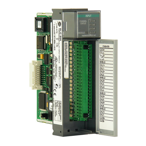
SLC 500 Thermocouple/mV Analog Input Module 1746-NT8 Features INPUT Channel Status CHANNEL LEDs (Green) Door Label STATUS MODULE Module Status THERMOCOUPLE/mV LED (Green) 1746-NT8 CJC A+ CJC A- Removable Terminal Block CHL 0+ CHL 0- SHIELD CHL 1+ CHL 1- CHL 2+ CHL 2- SHIELD... -
Page 6: Electrostatic Damage
SLC 500 Thermocouple/mV Analog Input Module Electrostatic Damage Electrostatic discharge can damage semiconductor devices inside this module if you touch backplane connector pins. Guard against electrostatic damage by observing the following precautions: ELECTROSTATICALLY SENSITIVE COMPONENTS ATTENTION • Before handling the module, touch a grounded object to rid yourself of electrostatic charge. -
Page 7: Considerations For A Modular System
SLC 500 Thermocouple/mV Analog Input Module Considerations for a Modular System Place your module in any slot of an SLC 500 modular, or modular expansion chassis, except for the left-most slot (slot 0) reserved for the SLC processor or adapter modules. Considerations for a Fixed Controller The power supply in the 2-slot SLC 500 fixed I/O chassis (1746-A2) can support only specific combinations of modules. -
Page 8: Module Installation And Removal
Apply firm even pressure on your module to attach it to its backplane connector. Never force your module into the slot. 4. Cover all unused slots with the Card Slot Filler, Allen-Bradley part number 1746-N2. Publication 1746-IN015C-EN-P - July 2001... -
Page 9: Terminal Block Removal
SLC 500 Thermocouple/mV Analog Input Module Terminal Block Removal To remove the terminal block: 1. Loosen the two terminal block release screws. To avoid cracking the terminal block, alternate between screws as you remove them. 2. Using a screwdriver or needle-nose pliers, carefully pry the terminal block loose. -
Page 10: Cold Junction Compensation (Cjc)
SLC 500 Thermocouple/mV Analog Input Module Cold Junction Compensation (CJC) To obtain accurate readings from each of the channels, the cold-junction temperature (temperature at the module’s terminal junction between the thermocouple wire and the input channel) must be compensated for. Two cold junction compensating sensors are integrated in the removable terminal block. -
Page 11: Thermocouple Junctions
SLC 500 Thermocouple/mV Analog Input Module Thermocouple Junctions There are three types of thermocouple junctions: • Grounded Junction - The measuring junction is physically connected to the protective metal sheath providing electrical continuity between junction and sheath. • Ungrounded Junction - The measuring junction is electrically isolated from the protective metal sheath. - Page 12 SLC 500 Thermocouple/mV Analog Input Module Grounded Junction Thermocouples 1746-NT8 Grounded junction with nonconductive MUXES protective sheath Metal sheath with electrical continuity to thermocouple signal wires. (floating ground connection) As shown in the wiring diagram above, it is recommended that grounded junction thermocouples have either protective sheaths made of electrically insulated material (e.g.
- Page 13 SLC 500 Thermocouple/mV Analog Input Module Exposed Junction Thermocouples 1746-NT8 Conductive Material MUXES CH 0 Exposed junction with shielded cable Nonconductive Material CH 3 Exposed junction with shielded cable Cable Wiring Considerations Follow these guidelines to wire your input signal cables: •...
-
Page 14: Preparing And Wiring The Cables
SLC 500 Thermocouple/mV Analog Input Module • Ground the shield drain wire at only one end of the cable. The preferred location is at the shield connections on the terminal block. (Refer to IEEE Std. 518, Section 6.4.2.7 or contact your sensor manufacturer for additional details.) •... - Page 15 SLC 500 Thermocouple/mV Analog Input Module 5. Connect the drain wires to the shield inputs of the terminal block if appropriate for thermocouple used. See “Wiring Guidelines” on page 10 for more information. • Channel 0 and 1 drain wires to pin 5 •...
- Page 16 SLC 500 Thermocouple/mV Analog Input Module Terminal Block Diagram with Input Cable CJC A+ Thermocouple or mV Cable CJC A- Channel 0+ Channel 0- Shield for CH0 and CH1 Channel 1+ Channel 1- Channel 2+ Channel 2- Shield for CH2 and CH3 Channel 3+ Channel 3- Channel 4+...
-
Page 17: Module Specifications
SLC 500 Thermocouple/mV Analog Input Module Module Specifications Electrical Specifications Backplane Current Consumption 120 mA at 5V dc, 70 mA at 24V dc Backplane Power Consumption 2.28W maximum (0.5W at 5V dc, 1.68W at 24V dc) Number of Channels 8 (backplane and channel-to-channel isolated) I/O Chassis Location Any I/O module slot except 0 A/D Conversion Method... - Page 18 SLC 500 Thermocouple/mV Analog Input Module Environmental Specifications Operating Temperature 0°C to +60°C (+32°F to +140°F) Storage Temperature -40°C to +85°C (-40°F to +185°F) Relative Humidity 5% to 95% (without condensation) Agency Certification UL and C-UL approved Hazardous Environment Classification Class I, Division 2 Hazardous Environment Groups A, B, C, D CE compliant for all applicable directives C-Tick compliant for all applicable acts...
- Page 19 SLC 500 Thermocouple/mV Analog Input Module See Module Accuracy Tables, in Appendix A of the SLC 500™ Overall Module Accuracy at 25°C Thermocouple/mV Analog Input Module manual, publication 1746-6.22. (77°F) Overall Module Accuracy (0°C to See Module Accuracy Tables, in Appendix A of the SLC 500™ 60°C, 32°F to 140°F) Thermocouple/mV Analog Input Module manual, publication 1746-6.22.
-
Page 20: For More Information
For More Information Refer to this Document Pub. No. A more detailed description on how to install SLC 500™ Thermocouple/mV 1746-6.22 and use your SLC 500™ Thermocouple/mV Analog Input Module User Manual Input Module A more detailed description on how to install SLC 500™...
Need help?
Do you have a question about the SLC500 and is the answer not in the manual?
Questions and answers