Sign In
Upload
Manuals
Brands
SEL Manuals
Relays
SEL-351S
SEL SEL-351S Protection System Manuals
Manuals and User Guides for SEL SEL-351S Protection System. We have
2
SEL SEL-351S Protection System manuals available for free PDF download: Instruction Manual
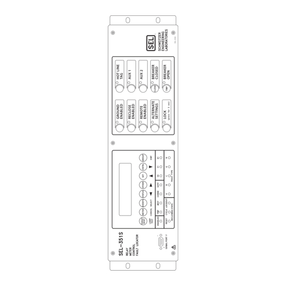
Sel SEL-351S Instruction Manual (760 pages)
Relay, Meter, Control, Fault Locator
Brand:
Sel
| Category:
Relays
| Size: 28 MB
Table of Contents
Table of Contents
4
List of Tables
8
List of Figures
12
Preface
18
Typographic Conventions
21
Cross References
21
Safety Information
22
Introduction and Specifications
24
SEL-351S Models
25
Table 1.1 SEL-351S Models
25
Table 1.2 SEL-351S Firmware Versions
26
Auxiliary {TRIP} and {CLOSE} Pushbuttons
26
CT Saturation Protection
26
Potential Transformer Connections
27
Applications
28
Figure 1.1 SEL-351S Relays Applied Throughout the Power System
28
Hardware Connection Features
29
Figure 1.2 Inputs, Outputs, and Communications Ports (Extra I/O Boards in Figure 1.3 and Figure 1.4)
29
Figure 1.3 Extra I/O Board (Model 0351Sxy, Plug-In Connector Version; Main Board Shown in Figure 1.2)
30
Figure 1.4 Extra I/O Board
31
Communications Connections
32
Figure 1.5 Communications Connections Examples
32
Specifications
33
Substation Battery Voltage Monitor
36
Metering Accuracy
36
Power Element Accuracy
37
Section 2: Installation
38
Relay Mounting
38
Rack Mount
38
Panel Mount
38
Figure 2.1 SEL-351S Dimensions for Rack-Mount and Panel-Mount Models
39
Front-Panel and Rear-Panel Connection Diagrams
40
Figure 2.2 SEL-351S Front- and Rear-Panel Drawings (Model 0351Sxyh3Xxxx6X); Horizontal Rack Mount Example, (Connectorized, with Additional I/O Board)
41
Figure 2.3 SEL-351S Front- and Rear-Panel Drawings (Model 0351Sx133Xxxx2X); Horizontal Panel Mount Example, (Conventional Terminal Blocks, with Additional I/O Board)
42
Figure 2.4 SEL-351S Front- and Rear-Panel Drawings (Model 0351Sx143Xxxxxx); Vertical Panel Mount Example, (Conventional Terminal Blocks, no Additional I/O Board)
43
Figure 2.5 SEL-351S with Auxiliary {TRIP}/{CLOSE} Pushbuttons (Model 0351Sx145Xxxx6X); Vertical Panel-Mount Example, (Conventional Terminal Blocks, with Additional I/O Board)
44
Figure 2.6 SEL-351S with Auxiliary {TRIP}/{CLOSE} Pushbuttons (Model 0351Sxyh5Xxxx2X); Horizontal Rack-Mount Example, (Connectorized, with Additional I/O Board)
45
User-Configurable Label Option for the Front Panel
46
Figure 2.7 SEL-351S (Horizontal) with User-Configurable Default Labels
46
Figure 2.8 SEL-351S (Horizontal) Blank Slide-In Label Set and Label Removal Tool
47
Figure 2.9 SEL-351S (Vertical) with User-Configurable Default Labels
48
Table 2.1 Options and Explanations for the User-Configurable Front-Panel Labels
50
Figure 2.11 Breaker LED Front-Panel Default Labels and Rear-Panel Labels
50
Making Rear-Panel Connections
51
Required Equipment/General Connection Information
51
Models 0351Sxy (Plug-In Connectors)
51
Figure 2.12 SEL-351S Plug-In Connector Coding (Top View; Model 0351Sxy)
52
Chassis Ground
53
Power Supply
53
Standard Output Contacts
54
High-Current Interrupting Output Contacts
54
Current Transformer Inputs
55
Model 0351Sxy
55
Potential Transformer Inputs
55
Voltage Input Rating
56
Wye-Connected Voltages (Global Setting PTCONN = WYE)
56
Delta-Connected Voltages (Global Setting PTCONN = DELTA)
56
Synchronism Check VS Connection (Global Setting VSCONN = VS)
57
Broken-Delta VS Connection (Global Setting VSCONN = 3V0)
57
Polarity Check for VSCONN = 3V0
57
Wye-Connected PT Example
58
Figure 2.13 Broken-Delta Secondary Connection to Voltage Input VS, Wye-Connected Pts
58
Figure 2.14 Resultant Voltage V
59
Figure 2.15 Broken-Delta Secondary Connection to Voltage Input VS, Open-Delta Connected Pts
59
Figure 2.16 Resultant Voltage V
60
Serial Ports
60
Table 2.2 Communication Cables to Connect the SEL-351S to Other Devices
61
IRIG-B Time-Code
61
SEL-351S AC/DC Connection Diagrams for Various Applications
62
Figure 2.17 SEL-351S Provides Overcurrent Protection and Reclosing for a Utility Distribution Feeder (Includes Fast Bus Trip Scheme) (Wye-Connected Pts)
62
Figure 2.18 SEL-351S Provides Overcurrent Protection for a Distribution Bus (Includes Fast Bus Trip Scheme) (Wye-Connected Pts)
63
Figure 2.19 SEL-351S Provides Directional Overcurrent Protection and Reclosing for a Transmission Line (Wye-Connected Pts)
64
Figure 2.20 SEL-351S Provides Directional Overcurrent Protection and Reclosing for a Transmission Line (Current-Polarization Source Connected to Channel IN) (Wye-Connected Pts)
65
Figure 2.21 SEL-351S Provides Overcurrent Protection for a Delta-Wye Transformer Bank (Wye-Connected Pts)
66
Figure 2.22 SEL-351S Provides Overcurrent Protection for a Transformer Bank with a Tertiary Winding (Wye-Connected Pts)
67
Figure 2.23 SEL-351S Provides Overcurrent Protection for an Industrial Distribution Feeder (Core-Balance Current Transformer Connected to Channel IN)
68
Figure 2.24 SEL-351S Provides Dedicated Breaker Failure Protection
69
Figure 2.25 SEL-351S Provides Overcurrent Protection for a High-Impedance or Low-Impedance Grounded System (Wye-Connected Pts)
70
Figure 2.26 SEL-351S Provides Overcurrent Protection for a Petersen Coil Grounded System (Wye-Connected Pts)
71
Figure 2.27 SEL-351S Provides Overcurrent Protection for an Ungrounded System (Wye-Connected Pts)
72
Figure 2.28 SEL-351S Provides Overcurrent Protection for an Ungrounded System (Open-Delta Connected Pts, Broken-Delta 3V0 Connection)
73
Figure 2.29 SEL-351S Provides Overcurrent Protection and Reclosing for a Utility Distribution Feeder (Open-Delta Connected Pts and Line-To-Ground Synch-Check Connection)
74
Figure 2.30 SEL-351S Provides Underfrequency Load Shedding, Overcurrent Protection, and Reclosing for a Utility Distribution Feeder (Single Voltage Connection)
75
Figure 2.31 SEL-351S Example Wiring Diagram Using the Auxiliary {TRIP}/{CLOSE} Pushbuttons for 0351Sxxx5/6/A/B Models
76
Circuit Board Connections
77
Figure 2.32 Jumper, Connector, and Major Component Locations on the SEL-351S Main Board
78
Figure 2.33 Jumper, Connector, and Major Component Locations on the SEL-351Sxy Extra I/O Board (Plug-In Connector Version)
79
Figure 2.34 Jumper, Connector, and Major Component Locations on the SEL-351Sx1 Extra I/O Board (Screw Terminal Block Version)
80
Figure 2.35 Jumper Locations for the 0351Sxxx5/6/A/B Model Magnetics/Auxiliary Pushbutton
81
Output Contact Jumpers
81
Table 2.3 Output Contact Jumpers and Corresponding Output Contacts
82
Table 2.4 "Extra Alarm" Output Contacts and Corresponding Controlling Jumpers
82
Table 2.5 Required Position of Jumper JMP23 for Desired Output Contact OUT107 Operation (Models 0351Sx1, and 0351Sxy)
82
Table 2.6 Password and Breaker Jumper Positions for Standard Relay Shipments
83
Table 2.7 Password and Breaker Jumper Operation
83
Table 2.8 EIA-232 Serial Port Voltage Jumper Positions for Standard Relay Shipments
83
Auxiliary {TRIP}/ {CLOSE} Pushbutton and Breaker Status LED Jumpers (0351Sxxx5/6/A/B Models Only)
84
Table 2.9 Jumper Positions for Breaker OPEN/CLOSE Indication
84
Table 2.10 Jumper Positions for Arc Suppression
84
Clock Battery
84
Phase Instantaneous/Definite-Time Overcurrent Elements
86
Section 3: Overcurrent, Voltage, Synchronism Check, Frequency, and Power Elements Instantaneous/Definite-Time Overcurrent Elements
87
Figure 3.1 Levels 1-4 Phase Instantaneous Overcurrent Elements
87
Figure 3.2 Levels 5-6 Phase Instantaneous Overcurrent Elements
87
Pickup Operation
88
Figure 3.3 Levels 1-4 Phase Instantaneous/Definite-Time Overcurrent Elements
89
Figure 3.4 Combined Single-Phase Instantaneous Overcurrent Elements
91
Pickup and Reset Time Curves
91
Figure 3.5 SEL-351S Nondirectional Instantaneous Overcurrent Element Pickup Time Curve
92
Figure 3.6 SEL-351S Nondirectional Instantaneous Overcurrent Element Reset Time Curve
92
Setting Range
92
Neutral Ground Instantaneous/Definite-Time Overcurrent Elements
93
Figure 3.7 Levels 1-4 Phase-To-Phase Instantaneous Overcurrent Elements
94
Figure 3.8 Levels 1-4 Neutral Ground Instantaneous/Definite-Time Overcurrent Elements
95
Figure 3.9 Levels 5-6 Neutral Ground Instantaneous Overcurrent Elements
96
Residual Ground Instantaneous/Definite-Time Overcurrent Elements
96
Figure 3.10 Levels 1-4 Residual Ground Instantaneous/Definite-Time Overcurrent Elements
98
Figure 3.11 Levels 5-6 Residual Ground Instantaneous Overcurrent Elements
99
Negative-Sequence
99
Figure 3.12 Levels 1-4 Negative-Sequence Instantaneous/Definite-Time Overcurrent Elements
100
Figure 3.13 Levels 5-6 Negative-Sequence Instantaneous Overcurrent Elements
101
Time-Overcurrent Elements
102
Table 3.1 Available Phase Time-Overcurrent Elements
102
Table 3.2 Phase Time-Overcurrent Elements Settings
102
Figure 3.14 Phase Time-Overcurrent Element 51P1T (with Directional Control Option)
103
Figure 3.15 Phase Time-Overcurrent Element 51P2T (with Directional Control Option)
103
Table 3.3 Phase Time-Overcurrent Element (Maximum Phase) Logic Outputs
104
Torque Control Switch Open
104
Directional Control Option
105
Torque Control
105
Reset Timing Details (51P1T Element Example)
106
Figure 3.16 Neutral Ground Time-Overcurrent Element 51N1T (with Directional Control Option)
107
Table 3.4 Neutral Ground Time-Overcurrent Elements Settings
108
Figure 3.17 Neutral Ground Time-Overcurrent Element 51N2T (with Directional Control Option)
108
Residual Ground Time-Overcurrent Elements
109
Figure 3.18 Residual Ground Time-Overcurrent Element 51G1T (with Directional Control Option)
109
Table 3.5 Residual Ground Time-Overcurrent Elements Settings
110
Figure 3.19 Residual Ground Time-Overcurrent Element 51G2T (with Directional Control Option)
110
Table 3.6 Negative-Sequence Time-Overcurrent Elements Settings
111
Figure 3.20 Negative-Sequence Time-Overcurrent Element 51QT (with Directional Control Option)
111
Voltage Elements
113
Table 3.7 Voltage Values Used by Voltage Elements
113
Voltage Element Settings
113
Table 3.8 Voltage Elements Settings and Settings Ranges (Wye-Connected Pts)
114
Table 3.9 Voltage Elements Settings and Settings Ranges (VS Channel)
114
Table 3.10 Voltage Elements Settings and Settings Ranges (Delta-Connected Pts)
115
Figure 3.21 Single-Phase and Three-Phase Voltage Elements (Wye-Connected Pts)
116
Figure 3.22 Phase-To-Phase and Sequence Voltage Elements (Wye-Connected Pts)
117
Figure 3.23 Phase-To-Phase Voltage Elements (Delta-Connected Pts)
118
Figure 3.24 Sequence Voltage Elements (Delta-Connected Pts)
118
Figure 3.25 Channel VS Voltage Elements (Wye- or Delta-Connected Pts)
119
Undervoltage Element Operation Example
119
Overvoltage Element Operation Example
119
Voltage Elements Used in POTT Logic
120
Synchronism Check Elements
121
Table 3.11 Synchronism Check Elements Settings and Settings Ranges
121
Setting SYNCP
122
Wye-Connected Voltages
122
Delta-Connected Voltages
122
Figure 3.26 Synchronism Check Voltage Window and Slip Frequency Elements
123
Figure 3.27 Synchronism Check Elements
123
System Frequencies Determined from Voltages
125
System Rotation Can Affect Setting SYNCP
126
Other Uses for Voltage Window Elements
126
Block Synchronism Check Conditions
126
Slip Frequency Calculator
127
Generator Application for SSLOW and SFAST
127
Angle Difference Calculator
128
Angle Difference Example
129
Figure 3.28 Angle Difference between V
130
Synchronism Check Element Outputs
131
Synchronism Check Applications for Automatic Reclosing and Manual Closing
132
Frequency Elements
134
Frequency Element Settings
134
Figure 3.31 Levels 1-6 Frequency Elements
135
Table 3.12 Frequency Elements Settings and Settings Ranges
136
Create Over- and Underfrequency Elements
136
Overfrequency Element
136
Overfrequency Element Operation
137
Underfrequency Element Operation
137
Frequency Element Voltage Control
137
Other Uses for Undervoltage Element 27B81
138
Frequency Element Uses
138
Underfrequency Loadshedding
138
Voltage Sag, Swell, and Interruption Elements (Available in Firmware Version 7)
139
Figure 3.32 Voltage Sag Elements
139
Figure 3.33 Voltage Swell Elements
140
Figure 3.34 Voltage Interruption Elements
140
Voltage Sag, Swell, and Interruption Elements Settings
140
Table 3.13 Sag/Swell/Interruption Elements Settings (Must First Set ESSI = Y)
141
Vbase Thermal Element Block
141
Figure 3.35 Vbase Tracking Example (Three-Phase Disturbance, Wye Connected)
142
Vbase Initialization
142
Vbase Tracking Range
143
SSI Reset Command
143
Power Elements (Available in Firmware Version 7)
144
Power Elements Settings
144
Table 3.14 Single-Phase Power Element Settings and Setting Ranges (EPWR = 1, 2, 3, or 4)
144
Table 3.15 Three-Phase Power Element Settings and Setting Ranges (EPWR = 3P1, 3P2, 3P3, or 3P4)
144
Power Element Time Delay Setting Considerations
145
Using Power Elements in the Relay Trip Equation
145
Single-Phase Power Element Calculations
147
Three-Phase Power Element Calculations
147
Power Elements Logic Operation
147
Figure 3.36 Single-Phase Power Elements Logic (+VARS Example Shown)
147
Figure 3.37 Three-Phase Power Elements Logic
148
Figure 3.38 Power Elements Operation in the Real/Reactive Power Plane
148
Figure 3.39 SEL-351S(B) Provides VAR Control for 9600 Kvar Capacitor Bank
149
Figure 3.40 Per Unit Setting Limits for Switching 9600 Kvar Capacitor Bank On- and Off-Line
151
Settings for Single-Phase Power Elements
151
Settings for Three-Phase Power Elements
152
Section 4: Loss-Of-Potential, Load Encroachment, and Directional Element Logic
154
Loss-Of-Potential Logic
154
Table 4.1 LOP Logic Inputs
154
Figure 4.1 Loss-Of-Potential Logic
154
Setting VNOM = off
155
Setting ELOP
155
Setting ELOP = y
156
Setting ELOP = N
156
Load-Encroachment Logic
157
Figure 4.2 Load-Encroachment Logic
157
Table 4.2 Load-Encroachment Settings Ranges
158
Load-Encroachment Setting Example
158
Convert Maximum Loads to Equivalent Secondary Impedances
158
Convert Power Factors to Equivalent Load Angles
159
Figure 4.3 Migration of Apparent Positive-Sequence Impedance for a Fault Condition
160
Directional Control for Neutral Ground and Residual Ground Overcurrent Elements
162
Figure 4.4 General Logic Flow of Directional Control for Neutral Ground and Residual Ground Overcurrent Elements (Excluding Ungrounded/High-Impedance Grounded Systems)
163
Table 4.3 Available Ground Directional Elements
164
Table 4.4 Best Choice Ground Directional™ Logic
164
Figure 4.5 General Logic Flow of Directional Control for Neutral Ground and Residual Ground Overcurrent Elements (Ungrounded/High-Impedance Grounded Systems; ORDER = U)
164
Table 4.5 Ground Directional Element Availability by Voltage Connection Settings
166
Internal Enables
167
Zero-Sequence Voltage Sources
168
Directional Elements
169
Directional Element Routing
170
Loss-Of-Potential
170
Figure 4.6 Internal Enables (32QE and 32QGE) Logic for Negative-Sequence Voltage-Polarized Directional Elements
172
Figure 4.7 Internal Enables (32VE and 32IE) Logic for Zero-Sequence Voltage-Polarized and Channel in Current-Polarized Directional Elements
173
Figure 4.8 Internal Enable (32NE) Logic for Zero-Sequence Voltage-Polarized Directional Elements (Low-Impedance Grounded, Petersen Coil Grounded, and Ungrounded/High-Impedance Grounded Systems)
174
Figure 4.9 Negative-Sequence Voltage-Polarized Directional Element for Neutral Ground and Residual Ground Overcurrent Elements
175
Figure 4.10 Zero-Sequence Voltage-Polarized Directional Element
176
Figure 4.11 Channel in Current-Polarized Directional Element
177
Figure 4.12 Zero-Sequence Voltage-Polarized Directional Element (Low-Impedance Grounded Systems)
178
Figure 4.13 Wattmetric and Incremental Conductance Directional Elements (Petersen Coil Grounded Systems)
179
Figure 4.14 Zero-Sequence Voltage-Polarized Directional Element (Ungrounded/High-Impedance Grounded Systems)
180
Figure 4.15 Routing of Directional Elements to Residual Ground Overcurrent Elements
181
Figure 4.16 Routing of Direction Elements to Neutral Ground Overcurrent Elements
181
Figure 4.17 Direction Forward/Reverse Logic for Residual Ground Overcurrent Elements
182
Figure 4.18 Direction Forward/Reverse Logic for Neutral Ground Overcurrent Elements
183
Directional Control for Negative-Sequence and Phase Overcurrent Elements
184
Figure 4.19 General Logic Flow of Directional Control for Negative-Sequence and Phase Overcurrent Elements
184
Direction Forward/Reverse Logic
186
Figure 4.20 Negative-Sequence Voltage-Polarized Directional Element for Negative-Sequence and Phase Overcurrent Elements
187
Figure 4.21 Positive-Sequence Voltage-Polarized Directional Element for Phase Overcurrent Elements
188
Figure 4.22 Routing of Directional Elements to Negative-Sequence and Phase Overcurrent Elements
189
Figure 4.23 Direction Forward/Reverse Logic for Negative-Sequence Overcurrent Elements
190
Figure 4.24 Direction Forward/Reverse Logic for Phase Overcurrent Elements
191
Directional Control Settings
192
Table 4.6 Directional Control Settings Not Made for Particular Conditions
193
Table 4.7 Overcurrent Elements Controlled by Level Direction Settings DIR1-DIR4
193
ORDER-Ground Directional Element Priority Setting
194
Petersen Coil Considerations for Setting ORDER
195
Table 4.8 Z Constant for Z2R Setting
196
K2 Set Automatically
198
Z0F and Z0R Set Automatically
201
Table 4.9 Z Constant for Z0R Setting
201
Deriving Z0F and Z0R Settings
201
Figure 4.25 Zero-Sequence Impedance Network and Relay Polarity
202
Figure 4.26 Zero-Sequence Impedance Plot for Solidly-Grounded, Mostly Inductive System
202
Figure 4.27 Zero-Sequence Impedance Network for Ground Fault on Feeder 1
205
Figure 4.28 Wattmetric Element Operation for Ground Fault on Feeder 1
206
32WD-Wattmetric Delay (Petersen Coil Grounded System)
207
Settings Considerations for Petersen Coil Grounded Systems
207
Table 4.10 Affect of Global Settings VSCONN and PTCONN on Petersen Coil Directional
209
E32IV-SEL OGIC Control Equation Enable
209
Ungrounded/High-Impedance Grounded System Considerations for Setting E32IV
210
Directional Control Provided by Torque Control Settings
211
Trip and Target Logic
212
Figure 5.1 Trip Logic
213
Figure 5.2 Minimum Trip Duration Timer Operation (See Bottom of Figure 5.1)
214
Unlatch Trip
214
Section 5: Trip and Target Logic Trip Logic
215
Other Applications for the Target Reset Function
215
Factory Settings Example (Using Setting TR)
215
Unlatch Trip with 52A Circuit Breaker Auxiliary Contact
216
Unlatch Trip with 52B Circuit Breaker Auxiliary Contact
216
Switch-Onto-Fault (SOTF) Trip Logic
219
Figure 5.3 Three-Pole Open Logic (Top) and Switch-Onto-Fault Logic (Bottom)
219
Circuit Breaker Operated Switch-Onto-Fault Logic
220
Switch-Onto-Fault Logic Output (SOTFE)
221
Switch-Onto-Fault Trip Logic Trip Setting (TRSOTF)
221
Communications-Assisted Trip Logic-General Overview
222
Figure 5.4 Communications-Assisted Tripping Scheme
222
Trip Setting TRCOMM
223
Trip Setting DTT
224
Permissive Overreaching Transfer Trip (POTT) Logic
226
External Inputs
226
PT1-Received Permissive Trip Signal(S)
226
Figure 5.5 Permissive Input Logic Routing to POTT Logic
227
Timer Settings
227
Logic Outputs
227
EKEY-Echo Key Permissive Trip
228
Figure 5.6 POTT Logic
229
Figure 5.7 Permissive Input Logic Routing to Trip Logic
230
Variations for Permissive Underreaching Transfer Trip (PUTT) Scheme
230
Installation Variations
230
Figure 5.8 SEL-351S Connections to Communications Equipment for a Two-Terminal Line POTT Scheme
231
Figure 5.9 SEL-351S Connections to Communications Equipment for a Three-Terminal Line POTT Scheme
231
Directional Comparison Unblocking (DCUB) Logic
232
Figure 5.10 DCUB Logic
235
Figure 5.11 Unblocking Block Logic Routing to Trip Logic
236
PTRX1, PTRX2-Permissive Trip Receive Outputs
236
Figure 5.12 SEL-351S Connections to Communications Equipment for a Two-Terminal Line DCUB Scheme (Setting ECOMM = DCUB1)
236
Figure 5.13 SEL-351S Connections to Communications Equipment for a Three-Terminal Line DCUB Scheme (Setting ECOMM = DCUB2)
237
Directional Comparison Blocking (DCB) Logic
238
DSTRT-Directional Carrier Start
239
NSTRT-Nondirectional Carrier Start
239
BTX-Block Trip Extension
240
Figure 5.14 DCB Logic
240
Figure 5.15 SEL-351S Connections to Communications Equipment for a Two-Terminal Line DCB Scheme
241
Figure 5.16 SEL-351S Connections to Communications Equipment for a Three-Terminal Line DCB Scheme
242
Front-Panel Target Leds
243
Table 5.1 SEL-351S Front-Panel Target LED Definitions and Settings
243
Figure 5.17 Programmable Front-Panel Target LED Logic
244
Front-Panel Target LED Logic Details
244
Target Reset/Lamp Test Front-Panel Pushbutton
247
Figure 5.18 Seal-In of Breaker Failure Occurrence for Message Display
247
Close and Reclose Logic
250
Section 6: Close and Reclose Logic Close Logic
251
Figure 6.1 Close Logic
251
Set Close
251
Unlatch Close
252
Factory Settings Example
252
Figure 6.2 Close Conditions-Other than Auto-Reclosing
253
Figure 6.3 Unlatch Close Conditions
254
Circuit Breaker Status
254
Figure 6.4 Breaker Status Determination
255
Program an Output Contact for Closing
255
Reclose Supervision Logic
256
Figure 6.5 Reclose Supervision Logic (Following Open-Interval Time-Out)
256
Figure 6.6 Reclose Supervision Limit Timer Operation (Refer to Bottom of Figure 6.5)
257
Settings and General Operation
257
For most Applications
257
For a Few, Unique Applications
258
Additional Settings
260
Figure 6.7 SEL-351S Relays Installed at both Ends of a Transmission Line in a High-Speed Reclose Scheme
260
Additional Settings Example
261
Reclosing Relay
263
Table 6.1 Relay Word Bit and Front-Panel Correspondence to Reclosing Relay States
264
Figure 6.8 Reclosing Relay States and General Operation
264
Reclosing Relay States and Settings/Setting Group Changes
265
Lockout State
265
Defeat the Reclosing Relay
266
Close Logic Can Still Operate When the Reclosing Relay Is Defeated
266
Table 6.2 Reclosing Relay Timer Settings and Setting Ranges
266
Open-Interval Timers
267
Figure 6.9 Example Reclosing Sequence from Reset to Lockout
267
Determination of Number of Reclosures (Last Shot)
267
Observe Shot Counter Operation
268
Reset Timer
268
Monitoring Open-Interval and Reset Timing
269
Reclosing Relay Shot Counter
269
Table 6.3 Shot Counter Correspondence to Relay Word Bits and Open-Interval Times
269
Reclose Initiate and Reclose Initiate Supervision Settings
270
Other Settings Considerations
271
Drive-To-Lockout and Drive-To-Last Shot Settings (79DTL and 79DLS, Respectively)
272
Figure 6.10 Factory-Default Drive-To-Lockout Logic
273
Table 6.5 Example Open-Interval Time Settings
274
Figure 6.11 Reclose Blocking for Islanded Generator
275
Additional Settings Example
275
Sequence Coordination Setting (79SEQ)
277
Figure 6.13 Operation of SEL-351S Shot Counter for Sequence Coordination with Line Recloser
278
Reclose Supervision Setting (79CLS)
280
Inputs, Outputs, Timers, and Other Control Logic
282
Optoisolated Inputs
283
Figure 7.1 Example Operation of Optoisolated Inputs IN101-IN106
283
Figure 7.2 Example Operation of Optoisolated Inputs IN201-IN208-Extra I/O Board
284
Input Debounce Timers
284
Input Functions
285
Settings Examples
285
Figure 7.3 Circuit Breaker Auxiliary Contact and Reclose Enable Switch Connected to Optoisolated Inputs IN101 and IN102
285
Local Control Switches
287
Figure 7.4 Local Control Switches Drive Local Bits LB1-LB16
287
Table 7.1 Correspondence between Local Control Switch Positions and Label Settings
287
On/Off Switch
287
Table 7.2 Correspondence between Local Control Switch Types and Required Label Settings
288
Figure 7.5 Local Control Switch Configured as an ON/OFF Switch
288
Figure 7.6 Local Control Switch Configured as an OFF/MOMENTARY Switch
288
Figure 7.7 Local Control Switch Configured as an ON/OFF/MOMENTARY Switch
288
Figure 7.8 Configured Manual Trip Switch Drives Local Bit LB3
289
Figure 7.9 Configured Manual Close Switch Drives Local Bit LB4
289
Remote Control Switches
291
Figure 7.10 Remote Control Switches Drive Remote Bits RB1-RB16
291
Latch Control Switches
293
Figure 7.11 Traditional Latching Relay
293
Figure 7.12 Latch Control Switches Drive Latch Bits LT1-LT16
293
Latch Control Switch Application Ideas
294
Reclosing Relay Enable/Disable Setting Example
294
Figure 7.13 SCADA Contact Pulses Input IN104 to Enable/Disable Reclosing Relay
294
Figure 7.14 Latch Control Switch Controlled by a Single Input to Enable/Disable Reclosing
294
Feedback Control
295
Rising Edge Operators
295
Figure 7.15 Latch Control Switch Operation Time Line
296
Use a Remote Bit Instead to Enable/Disable the Reclosing Relay
296
Latch Control Switch States Retained
296
Figure 7.16 Time Line for Reset of Latch Bit LT2 after Active Setting Group Change
297
Note: Make Latch Control Switch Settings with Care
297
Figure 7.17 Latch Control Switch (with Time Delay Feedback) Controlled by a Single Input to Enable/Disable Reclosing
298
Figure 7.18 Latch Control Switch (with Time Delay Feedback) Operation Time Line
299
Multiple Setting Groups
300
Table 7.3 Definitions for Active Setting Group Indication Relay Word Bits SG1-SG6
300
Selecting the Active Setting Group
300
Push Button
301
Relay Disabled Momentarily During Active Setting Group Change
301
Table 7.5 SEL OGIC Control Equation Settings for Switching Active Setting Group between Setting Groups 1 and
302
Figure 7.19 SCADA Contact Pulses Input IN105 to Switch Active Setting Group between Setting Groups 1 and
302
Table 7.6 Active Setting Group Switching Input Logic
304
Figure 7.21 Active Setting Group Switching (with Single Input) Time Line
304
Figure 7.22 Rotating Selector Switch Connected to Inputs IN101, IN102, and IN103 for Active Setting Group Switching
305
Selector Switch Now Rests on Position REMOTE
306
Figure 7.23 Active Setting Group Switching (with Rotating Selector Switch) Time Line
307
Active Setting Group Retained
307
Settings Change
307
Note: Make Active Setting Group Switching Settings with Care
308
SEL OGIC Control Equation Variables/Timers
309
Settings Example
310
Output Contacts
313
Operation of Output Contacts for Different Output Contact Types
313
ALARM Output Contact
314
Figure 7.27 Logic Flow for Example Output Contact Operation
315
Figure 7.28 Logic Flow for Example Output Contact Operation-Extra I/O Board
316
Rotating Default Display
317
Figure 7.29 Traditional Panel Light Installations
317
Reclosing Relay Status Indication
317
Circuit Breaker Status Indication
317
Figure 7.30 Rotating Default Display Replaces Traditional Panel Light Installations
318
General Operation of Rotating Default Display Settings
318
Reclosing Relay Enabled
318
Additional Settings Examples
320
Continually Display a Message
320
Active Setting Group Switching Considerations
321
Setting Group 1 Is the Active Setting Group
321
Displaying Values (Other than Userentered Text) on the Rotating Default Display
322
Values Displayed for Incorrect Settings
323
Table 7.8 Mnemonic Settings for Metering on the Rotating Default Display
324
Extra Details for Displaying Breaker Wear Monitor Quantities on the Rotating Default Display
327
Section 8: Breaker Monitor, Metering, and Load Profile Functions
327
Table 7.9 Mnemonic Settings for Breaker Wear Monitor Values on the Rotating Default Display
328
Extra Details for Displaying Time-Overcurrent Elements on the Rotating Default Display
328
Displaying Time-Overcurrent Elements Example
329
Table 7.10 Mnemonic Settings for Time-Overcurrent (TOC) Element Pickups on the Rotating Default
330
Additional Format for Displaying Time-Overcurrent Elements on the Rotating Default Display
330
Table 7.11 Mnemonic Settings for Time-Overcurrent (TOC) Element Pickups Using the Same-Line-Label Format on the Rotating Default Display
330
Control Strings
332
Breaker Monitor, Metering, and Load Profile Functions
334
Introduction
334
Breaker Monitor
335
Table 8.1 Breaker Maintenance Information for a 25 Kv Circuit Breaker
335
Breaker Monitor Setting Example
336
Figure 8.1 Plotted Breaker Maintenance Points for a 25 Kv Circuit Breaker
336
Table 8.2 Breaker Monitor Settings and Settings Ranges
336
Breaker Maintenance Curve Details
337
Figure 8.2 SEL-351S Breaker Maintenance Curve for a 25 Kv Circuit Breaker
338
Figure 8.3 Operation of SEL OGIC Control Equation Breaker Monitor Initiation Setting
339
Breaker Monitor Operation Example
339
Percent to 25 Percent Breaker Wear
340
Percent to 50 Percent Breaker Wear
340
Percent to 100 Percent Breaker Wear
340
Figure 8.4 Breaker Monitor Accumulates 10 Percent Wear
341
Figure 8.5 Breaker Monitor Accumulates 25 Percent Wear
342
Figure 8.6 Breaker Monitor Accumulates 50 Percent Wear
343
Figure 8.7 Breaker Monitor Accumulates 100 Percent Wear
344
Breaker Monitor Output
344
Via Serial Port
345
Determination of Relay Initiated Trips and Externally Initiated Trips
345
Factory Default Setting Example
346
Additional Example
346
Figure 8.8 Input IN106 Connected to Trip Bus for Breaker Monitor Initiation
346
Station DC Battery Monitor
348
Figure 8.9 DC Under- and Overvoltage Elements
348
Create Desired Logic for DC Under- and Overvoltage Alarming
348
View Station DC Battery Voltage
350
Station DC Battery Voltage Dips During Circuit Breaker Tripping
351
Station DC Battery Voltage Dips During Circuit Breaker Closing
351
Station DC Battery Voltage Dips Anytime
351
Powering the Relay
352
Demand Metering
353
Comparison of Thermal and Rolling Demand Meters
353
Figure 8.11 Response of Thermal and Rolling Demand Meters to a Step Input (Setting DMTC = 15 Minutes)
354
Thermal Demand Meter Response (EDEM = THM)
355
Figure 8.12 Voltage
355
Rolling Demand Meter Response (EDEM = ROL)
355
Time = 0 Minutes
356
Time = 5 Minutes
356
Time = 10 Minutes
356
Time = 15 Minutes
357
Table 8.3 Demand Meter Settings and Settings Range
357
Demand Current Logic Output Application-Raise Pickup for Unbalance Current
358
Figure 8.14 Raise Pickup of Residual Ground Time-Overcurrent Element for Unbalance Current
359
Residual Ground Demand Current below Pickup GDEMP
359
Residual Ground Demand Current Goes above Pickup GDEMP
359
Demand Metering Updating and Storage
361
Energy Metering
362
Energy Metering Updating and Storage
362
Maximum/Minimum Metering
363
Table 8.4 Operation of Maximum/Minimum Metering with Directional Power Quantities
363
Maximum/Minimum Metering Update and Storage
364
Small Signal Cutoff for Metering
365
Table 8.5 Metering Thresholds (Secondary Units)
365
Synchrophasor Metering
366
View Synchrophasor Metering Information Via Serial Port
366
Load Profile Report (Available in Firmware Versions 6 and 7)
367
Determining the Size of the Load Profile Buffer
370
Clearing the Load Profile Buffer
370
Setting the Relay
372
Table 9.1 Serial Port SET Commands
372
In some Applications, Make Global Settings (SET G) First
372
Section 9: Setting the Relay Introduction
373
Settings Changes Via the Front Panel
374
Settings Changes Via the Serial Port
375
Table 9.2 Set Command Editing Keystrokes
375
Time-Overcurrent Curves
376
Table 9.3 Equations Associated with U.S. Curves
376
Table 9.4 Equations Associated with IEC Curves
376
Recloser Curves
377
Table 9.5 Recloser Curve Designations
377
Figure 9.1 U.S. Moderately Inverse Curve: U1
378
Figure 9.2 U.S. Inverse Curve: U2
379
Figure 9.3 U.S. very Inverse Curve: U3
380
Figure 9.4 U.S. Extremely Inverse Curve: U4
381
Figure 9.5 U.S. Short-Time Inverse Curve: U5
382
Figure 9.6 I.E.C. Class a Curve (Standard Inverse): C1
383
Figure 9.7 I.E.C. Class B Curve (very Inverse): C2
384
Figure 9.8 I.E.C. Class C Curve (Extremely Inverse): C3
385
Figure 9.9 I.E.C. Long-Time Inverse Curve: C4
386
Figure 9.10 I.E.C. Short-Time Inverse Curve: C5
387
Figure 9.11 Recloser Control Response Curves A, C, N, and W
388
Figure 9.12 Recloser Control Response Curves B, R, 2, and 3
389
Figure 9.13 Recloser Control Response Curves D, 8PLUS, and 16
390
Figure 9.14 Recloser Control Response Curves F, H, J, and 1
391
Figure 9.15 Recloser Control Response Curves G, V, 6, and 13
392
Figure 9.16 Recloser Control Response Curves E, P, and 18
393
Figure 9.17 Recloser Control Response Curves KG, Y, Z, and 5
394
Figure 9.18 Recloser Control Response Curves KP, M, T, and 17
395
Figure 9.19 Recloser Control Response Curves 4, 9, 11, and 14
396
Figure 9.20 Recloser Control Response Curves L, 7, 8, and 15
397
Relay Word Bits (Used in SEL OGIC Control Equations)
398
Table 9.6 SEL-351S Relay Word Bits
398
Table 9.7 Relay Word Bit Definitions for SEL-351S
400
Settings Explanations
419
Identifier Labels
419
Current Transformer Ratios
419
Settings for Voltage Input Configuration
421
Table 9.8 Main Relay Functions that Change with VSCONN, When PTCONN = WYE
422
Table 9.9 Main Relay Functions that Change with VSCONN, When PTCONN = DELTA
423
Figure 9.21 Operation of DELTA and 3V0 Relay Word Bits
423
Table 9.10 Main Relay Functions that Change with VNOM = off
424
Potential Transformer Ratios and PT Nominal Secondary Voltage Settings
424
Line Settings
425
Figure 9.22 Hybrid Power System with Neutral Ground Resistor
425
Other System Parameters
426
Settings Sheets
428
SEL-351S Settings Sheets
430
Relay Settings
430
Instantaneous/Definite-Time Overcurrent Enable Settings
431
Time-Overcurrent Enable Settings
431
Other Enable Settings
431
Phase-To-Phase Instantaneous Overcurrent Elements
433
Phase Time-Overcurrent Element
435
Frequency Element
441
Other Settings
443
Power Elements
444
Communications-Assisted Trip Scheme Input Equations
447
Torque Control Equations for Inst./Def.-Time Overcurrent Elements
449
Torque Control Equations for Time-Overcurrent Elements
449
Advertisement
SEL SEL-351S Instruction Manual (758 pages)
Relay, Meter, Control, Fault Locator
Brand:
SEL
| Category:
Relays
| Size: 7 MB
Table of Contents
Table of Contents
3
List of Tables
7
List of Figures
11
Table of Contents
12
Preface
17
Section 1: Introduction and Specifications
24
SEL-351S Models
24
Table 1.1 SEL-351S Models
24
Table 1.2 SEL-351S Firmware Versions
25
Applications
27
Hardware Connection Features
28
Communications Connections
31
Specifications
32
Section 2: Installation
37
Relay Mounting
37
Front-Panel and Rear-Panel Connection Diagrams
39
User-Configurable Label Option for the Front Panel
45
Table 2.1 Options and Explanations for the User-Configurable Front-Panel Labels
49
Making Rear-Panel Connections
50
Table 2.2 Communication Cables to Connect the SEL-351S to Other Devices
60
SEL-351S AC/DC Connection Diagrams for Various Applications
61
Figure 2.30 SEL-351S Provides Underfrequency Load Shedding, Overcurrent Protection, and
74
Figure 2.31 SEL-351S Example Wiring Diagram Using the Auxiliary {TRIP}/{CLOSE} Pushbuttons for 0351Sxxx5/6/A/B Models
75
Circuit Board Connections
76
Figure 2.32 Jumper, Connector, and Major Component Locations on the SEL-351S Main Board
77
Figure 2.33 Jumper, Connector, and Major Component Locations on the SEL-351Sxy Extra
78
Figure 2.34 Jumper, Connector, and Major Component Locations on the SEL-351Sx1 Extra
79
Figure 2.35 Jumper Locations for the 0351Sxxx5/6/A/B Model Magnetics/Auxiliary Pushbutton Board
80
Table 2.3 Output Contact Jumpers and Corresponding Output Contacts
81
Table 2.4 "Extra Alarm" Output Contacts and Corresponding Controlling Jumpers
81
Table 2.5 Required Position of Jumper JMP23 for Desired Output Contact OUT107 Operation (Models 0351Sx1, and 0351Sxy)
81
Table 2.6 Password and Breaker Jumper Positions for Standard Relay Shipments
82
Table 2.7 Password and Breaker Jumper Operation
82
Table 2.8 EIA-232 Serial Port Voltage Jumper Positions for Standard Relay Shipments
82
Table 2.9 Jumper Positions for Breaker OPEN/CLOSE Indication
83
Table 2.10 Jumper Positions for Arc Suppression
83
Section 3: Overcurrent, Voltage, Synchronism Check, Frequency, and Power Elements
85
Instantaneous/Definite-Time Overcurrent Elements
85
Figure 3.1 Levels 1-4 Phase Instantaneous Overcurrent Elements
86
Figure 3.2 Levels 5-6 Phase Instantaneous Overcurrent Elements
86
Figure 3.3 Levels 1-4 Phase Instantaneous/Definite-Time Overcurrent Elements
88
Figure 3.4 Combined Single-Phase Instantaneous Overcurrent Elements
90
Figure 3.5 SEL-351S Nondirectional Instantaneous Overcurrent Element Pickup Time Curve
91
Figure 3.6 SEL-351S Nondirectional Instantaneous Overcurrent Element Reset Time Curve
91
Figure 3.7 Levels 1-4 Phase-To-Phase Instantaneous Overcurrent Elements
93
Figure 3.8 Levels 1-4 Neutral Ground Instantaneous/Definite-Time Overcurrent Elements (with Directional Control Option)
94
Figure 3.9 Levels 5-6 Neutral Ground Instantaneous Overcurrent Elements
95
Figure 3.10 Levels 1-4 Residual Ground Instantaneous/Definite-Time Overcurrent Elements
97
Figure 3.11 Levels 5-6 Residual Ground Instantaneous Overcurrent Elements
98
Figure 3.12 Levels 1-4 Negative-Sequence Instantaneous/Definite-Time Overcurrent Elements (with Directional Control Option)
99
Figure 3.13 Levels 5-6 Negative-Sequence Instantaneous Overcurrent Elements
100
Time-Overcurrent Elements
101
Table 3.1 Available Phase Time-Overcurrent Elements
101
Table 3.2 Phase Time-Overcurrent Elements Settings
101
Figure 3.14 Phase Time-Overcurrent Element 51P1T (with Directional Control Option)
102
Figure 3.15 Phase Time-Overcurrent Element 51P2T (with Directional Control Option)
102
Table 3.3 Phase Time-Overcurrent Element (Maximum Phase) Logic Outputs
103
Figure 3.16 Neutral Ground Time-Overcurrent Element 51N1T (with Directional Control Option)
106
Table 3.4 Neutral Ground Time-Overcurrent Elements Settings
107
Figure 3.17 Neutral Ground Time-Overcurrent Element 51N2T (with Directional Control Option)
107
Figure 3.18 Residual Ground Time-Overcurrent Element 51G1T (with Directional Control Option)
108
Table 3.5 Residual Ground Time-Overcurrent Elements Settings
109
Figure 3.19 Residual Ground Time-Overcurrent Element 51G2T (with Directional Control Option)
109
Table 3.6 Negative-Sequence Time-Overcurrent Elements Settings
110
Figure 3.20 Negative-Sequence Time-Overcurrent Element 51QT (with Directional Control Option)
110
Voltage Elements
112
Table 3.7 Voltage Values Used by Voltage Elements
112
Table 3.8 Voltage Elements Settings and Settings Ranges (Wye-Connected Pts)
113
Table 3.9 Voltage Elements Settings and Settings Ranges (VS Channel)
113
Table 3.10 Voltage Elements Settings and Settings Ranges (Delta-Connected Pts)
114
Figure 3.21 Single-Phase and Three-Phase Voltage Elements (Wye-Connected Pts)
115
Figure 3.22 Phase-To-Phase and Sequence Voltage Elements (Wye-Connected Pts)
116
Figure 3.23 Phase-To-Phase Voltage Elements (Delta-Connected Pts)
117
Figure 3.24 Sequence Voltage Elements (Delta-Connected Pts)
117
Figure 3.25 Channel VS Voltage Elements (Wye- or Delta-Connected Pts)
118
Synchronism Check Elements
120
Table 3.11 Synchronism Check Elements Settings and Settings Ranges
120
Figure 3.26 Synchronism Check Voltage Window and Slip Frequency Elements
122
Figure 3.27 Synchronism Check Elements
122
Figure 3.28 Angle Difference between V
129
Frequency Elements
133
Figure 3.31 Levels 1-6 Frequency Elements
134
Table 3.12 Frequency Elements Settings and Settings Ranges
135
Voltage Sag, Swell, and Interruption Elements (Available in Firmware Version 7)
138
Figure 3.32 Voltage Sag Elements
138
Figure 3.33 Voltage Swell Elements
139
Figure 3.34 Voltage Interruption Elements
139
Table 3.13 Sag/Swell/Interruption Elements Settings (Must First Set ESSI = Y)
140
Figure 3.35 Vbase Tracking Example (Three-Phase Disturbance, Wye Connected)
141
Power Elements (Available in Firmware Version 7)
143
Table 3.14 Single-Phase Power Element Settings and Setting Ranges (EPWR = 1, 2, 3, or 4)
143
Table 3.15 Three-Phase Power Element Settings and Setting Ranges (EPWR = 3P1, 3P2, 3P3, or 3P4)
143
Figure 3.36 Single-Phase Power Elements Logic (+VARS Example Shown)
146
Figure 3.37 Three-Phase Power Elements Logic
147
Figure 3.38 Power Elements Operation in the Real/Reactive Power Plane
147
Figure 3.39 SEL-351S(B) Provides VAR Control for 9600 Kvar Capacitor Bank
148
Figure 3.40 Per Unit Setting Limits for Switching 9600 Kvar Capacitor Bank On- and Off-Line
150
Section 4: Loss-Of-Potential, Load Encroachment, and Directional Element Logic
153
Loss-Of-Potential Logic
153
Table 4.1 LOP Logic Inputs
153
Figure 4.1 Loss-Of-Potential Logic
153
Load-Encroachment Logic
156
Figure 4.2 Load-Encroachment Logic
156
Table 4.2 Load-Encroachment Settings Ranges
157
Figure 4.3 Migration of Apparent Positive-Sequence Impedance for a Fault Condition
159
Directional Control for Neutral Ground and Residual Ground Overcurrent Elements
161
Figure 4.4 General Logic Flow of Directional Control for Neutral Ground and Residual Ground Overcurrent Elements (Excluding Ungrounded/High-Impedance Grounded Systems)
162
Table 4.3 Available Ground Directional Elements
163
Table 4.4 Best Choice Ground Directional™ Logic
163
Figure 4.5 General Logic Flow of Directional Control for Neutral Ground and Residual Ground Overcurrent Elements (Ungrounded/High-Impedance Grounded Systems; ORDER = U)
163
Table 4.5 Ground Directional Element Availability by Voltage Connection Settings
165
Figure 4.6 Internal Enables (32QE and 32QGE) Logic for Negative-Sequence Voltage-Polarized Directional Elements
171
Figure 4.7 Internal Enables (32VE and 32IE) Logic for Zero-Sequence Voltage-Polarized and Channel in Current-Polarized Directional Elements
172
Figure 4.8 Internal Enable (32NE) Logic for Zero-Sequence Voltage-Polarized Directional Elements (Low-Impedance Grounded, Petersen Coil Grounded, and Ungrounded/High-Impedance Grounded Systems)
173
Figure 4.9 Negative-Sequence Voltage-Polarized Directional Element for Neutral Ground and Residual Ground Overcurrent Elements
174
Figure 4.10 Zero-Sequence Voltage-Polarized Directional Element
175
Figure 4.11 Channel in Current-Polarized Directional Element
176
Figure 4.12 Zero-Sequence Voltage-Polarized Directional Element (Low-Impedance Grounded Systems)
177
Figure 4.13 Wattmetric and Incremental Conductance Directional Elements (Petersen Coil Grounded Systems)
178
Figure 4.14 Zero-Sequence Voltage-Polarized Directional Element (Ungrounded/High-Impedance Grounded Systems)
179
Figure 4.15 Routing of Directional Elements to Residual Ground Overcurrent Elements
180
Figure 4.16 Routing of Direction Elements to Neutral Ground Overcurrent Elements
180
Figure 4.17 Direction Forward/Reverse Logic for Residual Ground Overcurrent Elements
181
Figure 4.18 Direction Forward/Reverse Logic for Neutral Ground Overcurrent Elements
182
Directional Control for Negative-Sequence and Phase Overcurrent Elements
183
Figure 4.19 General Logic Flow of Directional Control for Negative-Sequence and Phase Overcurrent Elements
183
Figure 4.20 Negative-Sequence Voltage-Polarized Directional Element for Negative-Sequence and Phase Overcurrent Elements
186
Figure 4.21 Positive-Sequence Voltage-Polarized Directional Element for Phase Overcurrent Elements
187
Figure 4.22 Routing of Directional Elements to Negative-Sequence and Phase Overcurrent Elements
188
Figure 4.23 Direction Forward/Reverse Logic for Negative-Sequence Overcurrent Elements
189
Figure 4.24 Direction Forward/Reverse Logic for Phase Overcurrent Elements
190
Directional Control Settings
191
Table 4.6 Directional Control Settings Not Made for Particular Conditions
192
Table 4.7 Overcurrent Elements Controlled by Level Direction Settings DIR1-DIR4
192
Table 4.8 Z Constant for Z2R Setting
195
Table 4.9 Z Constant for Z0R Setting
200
Figure 4.25 Zero-Sequence Impedance Network and Relay Polarity
201
Figure 4.26 Zero-Sequence Impedance Plot for Solidly-Grounded, Mostly Inductive System
201
Figure 4.27 Zero-Sequence Impedance Network for Ground Fault on Feeder 1
204
Figure 4.28 Wattmetric Element Operation for Ground Fault on Feeder 1
205
Table 4.10 Affect of Global Settings VSCONN and PTCONN on Petersen Coil Directional Elements
208
Directional Control Provided by Torque Control Settings
210
Section 5: Trip and Target Logic Trip Logic
212
Figure 5.1 Trip Logic
212
Figure 5.2 Minimum Trip Duration Timer Operation (See Bottom of Figure 5.1)
213
Switch-Onto-Fault (SOTF) Trip Logic
218
Figure 5.3 Three-Pole Open Logic (Top) and Switch-Onto-Fault Logic (Bottom)
218
Communications-Assisted Trip Logic-General Overview
221
Figure 5.4 Communications-Assisted Tripping Scheme
221
Permissive Overreaching Transfer Trip (POTT) Logic
225
Figure 5.5 Permissive Input Logic Routing to POTT Logic
226
Figure 5.6 POTT Logic
228
Figure 5.7 Permissive Input Logic Routing to Trip Logic
229
Figure 5.8 SEL-351S Connections to Communications Equipment for a Two-Terminal Line POTT Scheme
230
Figure 5.9 SEL-351S Connections to Communications Equipment for a Three-Terminal Line POTT Scheme
230
Directional Comparison Unblocking (DCUB) Logic
231
Figure 5.10 DCUB Logic
234
Figure 5.11 Unblocking Block Logic Routing to Trip Logic
235
Figure 5.12 SEL-351S Connections to Communications Equipment for a Two-Terminal Line DCUB Scheme (Setting ECOMM = DCUB1)
235
Figure 5.13 SEL-351S Connections to Communications Equipment for a Three-Terminal Line DCUB Scheme (Setting ECOMM = DCUB2)
236
Directional Comparison Blocking (DCB) Logic
237
Figure 5.14 DCB Logic
239
Figure 5.15 SEL-351S Connections to Communications Equipment for a Two-Terminal Line DCB
240
Figure 5.16 SEL-351S Connections to Communications Equipment for a Three-Terminal Line DCB
241
Front-Panel Target Leds
242
Table 5.1 SEL-351S Front-Panel Target LED Definitions and Settings
242
Figure 5.17 Programmable Front-Panel Target LED Logic
243
Figure 5.18 Seal-In of Breaker Failure Occurrence for Message Display
246
Section 6: Close and Reclose Logic Close Logic
250
Figure 6.2 Close Conditions-Other than Auto-Reclosing
252
Figure 6.3 Unlatch Close Conditions
253
Figure 6.4 Breaker Status Determination
254
Reclose Supervision Logic
255
Figure 6.5 Reclose Supervision Logic (Following Open-Interval Time-Out)
255
Figure 6.6 Reclose Supervision Limit Timer Operation (Refer to Bottom of Figure 6.5)
256
Figure 6.7 SEL-351S Relays Installed at both Ends of a Transmission Line in a High-Speed Reclose
259
Reclosing Relay
262
Table 6.1 Relay Word Bit and Front-Panel Correspondence to Reclosing Relay States
263
Figure 6.8 Reclosing Relay States and General Operation
263
Table 6.2 Reclosing Relay Timer Settings and Setting Ranges
265
Figure 6.1 Close Logic
265
Figure 6.9 Example Reclosing Sequence from Reset to Lockout
266
Table 6.3 Shot Counter Correspondence to Relay Word Bits and Open-Interval Times
268
Figure 6.10 Factory-Default Drive-To-Lockout Logic
272
Table 6.5 Example Open-Interval Time Settings
273
Figure 6.11 Reclose Blocking for Islanded Generator
274
Figure 6.13 Operation of SEL-351S Shot Counter for Sequence Coordination with Line Recloser
277
Optoisolated Inputs
282
Figure 7.1 Example Operation of Optoisolated Inputs IN101-IN106
282
Figure 7.2 Example Operation of Optoisolated Inputs IN201-IN208-Extra I/O Board
283
Figure 7.3 Circuit Breaker Auxiliary Contact and Reclose Enable Switch Connected to Optoisolated
284
Local Control Switches
286
Table 7.1 Correspondence between Local Control Switch Positions and Label Settings
286
Figure 7.4 Local Control Switches Drive Local Bits LB1-LB16
286
Table 7.2 Correspondence between Local Control Switch Types and Required Label Settings
287
Figure 7.5 Local Control Switch Configured as an ON/OFF Switch
287
Figure 7.6 Local Control Switch Configured as an OFF/MOMENTARY Switch
287
Figure 7.7 Local Control Switch Configured as an ON/OFF/MOMENTARY Switch
287
Figure 7.8 Configured Manual Trip Switch Drives Local Bit LB3
288
Figure 7.9 Configured Manual Close Switch Drives Local Bit LB4
288
Remote Control Switches
290
Figure 7.10 Remote Control Switches Drive Remote Bits RB1-RB16
290
Latch Control Switches
292
Figure 7.11 Traditional Latching Relay
292
Figure 7.12 Latch Control Switches Drive Latch Bits LT1-LT16
292
Figure 7.13 SCADA Contact Pulses Input IN104 to Enable/Disable Reclosing Relay
293
Figure 7.14 Latch Control Switch Controlled by a Single Input to Enable/Disable Reclosing
293
Figure 7.15 Latch Control Switch Operation Time Line
295
Figure 7.16 Time Line for Reset of Latch Bit LT2 after Active Setting Group Change
296
Figure 7.17 Latch Control Switch (with Time Delay Feedback) Controlled by a Single Input to Enable/Disable Reclosing
297
Figure 7.18 Latch Control Switch (with Time Delay Feedback) Operation Time Line
298
Multiple Setting Groups
299
Table 7.3 Definitions for Active Setting Group Indication Relay Word Bits SG1-SG6
299
Table 7.5 SEL OGIC Control Equation Settings for Switching Active Setting Group between Setting Groups 1 and
301
Figure 7.19 SCADA Contact Pulses Input IN105 to Switch Active Setting Group between Setting Groups 1 and
301
Table 7.6 Active Setting Group Switching Input Logic
303
Figure 7.21 Active Setting Group Switching (with Single Input) Time Line
303
Figure 7.22 Rotating Selector Switch Connected to Inputs IN101, IN102, and IN103 for Active Setting Group Switching
304
Figure 7.23 Active Setting Group Switching (with Rotating Selector Switch) Time Line
306
SEL OGIC Control Equation Variables/Timers
308
Output Contacts
312
Figure 7.27 Logic Flow for Example Output Contact Operation
314
Figure 7.28 Logic Flow for Example Output Contact Operation-Extra I/O Board
315
Rotating Default Display
316
Figure 7.29 Traditional Panel Light Installations
316
Figure 7.30 Rotating Default Display Replaces Traditional Panel Light Installations
317
Table 7.8 Mnemonic Settings for Metering on the Rotating Default Display
323
Section 8: Breaker Monitor, Metering, and Load Profile Functions
326
Table 7.9 Mnemonic Settings for Breaker Wear Monitor Values on the Rotating Default Display
327
Table 7.10 Mnemonic Settings for Time-Overcurrent (TOC) Element Pickups on the Rotating Default
329
Table 7.11 Mnemonic Settings for Time-Overcurrent (TOC) Element Pickups Using the
329
Introduction
333
Breaker Monitor
334
Table 8.1 Breaker Maintenance Information for a 25 Kv Circuit Breaker
334
Table 8.2 Breaker Monitor Settings and Settings Ranges
335
Figure 8.1 Plotted Breaker Maintenance Points for a 25 Kv Circuit Breaker
335
Figure 8.2 SEL-351S Breaker Maintenance Curve for a 25 Kv Circuit Breaker
337
Figure 8.3 Operation of SEL OGIC Control Equation Breaker Monitor Initiation Setting
338
Figure 8.4 Breaker Monitor Accumulates 10 Percent Wear
340
Figure 8.5 Breaker Monitor Accumulates 25 Percent Wear
341
Figure 8.6 Breaker Monitor Accumulates 50 Percent Wear
342
Figure 8.7 Breaker Monitor Accumulates 100 Percent Wear
343
Figure 8.8 Input IN106 Connected to Trip Bus for Breaker Monitor Initiation
345
Station DC Battery Monitor
347
Figure 8.9 DC Under- and Overvoltage Elements
347
Demand Metering
352
Figure 8.11 Response of Thermal and Rolling Demand Meters to a Step Input (Setting DMTC = 15 Minutes)
353
Figure 8.12 Voltage V
354
Table 8.3 Demand Meter Settings and Settings Range
356
Figure 8.13 Demand Current Logic Outputs
357
Figure 8.14 Raise Pickup of Residual Ground Time-Overcurrent Element for Unbalance Current
358
Energy Metering
361
Maximum/Minimum Metering
362
Table 8.4 Operation of Maximum/Minimum Metering with Directional Power Quantities
362
Small Signal Cutoff for Metering
364
Table 8.5 Metering Thresholds (Secondary Units)
364
Synchrophasor Metering
365
Load Profile Report (Available in Firmware Versions 6 and 7)
366
Table 9.1 Serial Port SET Commands
371
Section 9: Setting the Relay Introduction
372
Settings Changes Via the Front Panel
373
Settings Changes Via the Serial Port
374
Table 9.2 Set Command Editing Keystrokes
374
Time-Overcurrent Curves
375
Table 9.3 Equations Associated with U.S. Curves
375
Table 9.4 Equations Associated with IEC Curves
375
Table 9.5 Recloser Curve Designations
376
Figure 9.1 U.S. Moderately Inverse Curve: U1
377
Figure 9.2 U.S. Inverse Curve: U2
378
Figure 9.3 U.S. very Inverse Curve: U3
379
Figure 9.4 U.S. Extremely Inverse Curve: U4
380
Figure 9.5 U.S. Short-Time Inverse Curve: U5
381
Figure 9.6 I.E.C. Class a Curve (Standard Inverse): C1
382
Figure 9.7 I.E.C. Class B Curve (very Inverse): C2
383
Figure 9.8 I.E.C. Class C Curve (Extremely Inverse): C3
384
Figure 9.9 I.E.C. Long-Time Inverse Curve: C4
385
Figure 9.10 I.E.C. Short-Time Inverse Curve: C5
386
Figure 9.11 Recloser Control Response Curves A, C, N, and W
387
Figure 9.12 Recloser Control Response Curves B, R, 2, and 3
388
Figure 9.13 Recloser Control Response Curves D, 8PLUS, and 16
389
Figure 9.14 Recloser Control Response Curves F, H, J, and 1
390
Figure 9.15 Recloser Control Response Curves G, V, 6, and 13
391
Figure 9.16 Recloser Control Response Curves E, P, and 18
392
Figure 9.17 Recloser Control Response Curves KG, Y, Z, and 5
393
Figure 9.18 Recloser Control Response Curves KP, M, T, and 17
394
Figure 9.19 Recloser Control Response Curves 4, 9, 11, and 14
395
Figure 9.20 Recloser Control Response Curves L, 7, 8, and 15
396
Relay Word Bits (Used in SEL OGIC Control Equations)
397
Table 9.6 SEL-351S Relay Word Bits
397
Table 9.7 Relay Word Bit Definitions for SEL-351S
399
Settings Explanations
418
Table 9.8 Main Relay Functions that Change with VSCONN, When PTCONN = WYE
421
Table 9.9 Main Relay Functions that Change with VSCONN, When PTCONN = DELTA
422
Figure 9.21 Operation of DELTA and 3V0 Relay Word Bits
422
Table 9.10 Main Relay Functions that Change with VNOM = off
423
Figure 9.22 Hybrid Power System with Neutral Ground Resistor
424
Settings Sheets
427
Table I.1 MIRRORED BITS
452
Section 10: Serial Port Communications and Commands
466
Port Connector and Communications Cables
466
Table 10.1 Pinout Functions for EIA-232 Serial Ports 2, 3, and
466
Table 10.2 Terminal Functions for EIA-485 Serial Port 1
466
Figure 10.1 DB-9 Connector Pinout for EIA-232 Serial Ports
466
Table 10.3 Serial Communications Port Pin/Terminal Function Definitions
468
Communications Protocol
470
Serial Port Automatic Messages
473
Table 10.4 Serial Port Automatic Messages
473
Serial Port Access Levels
474
Table 10.5 Serial Port Command Summary
476
Table 10.6 SEL-351S Word and Its Correspondence to TAR Command
499
Table 10.7 SEL-351S Control Subcommand
505
Table 10.8 Factory Default Passwords for Access Levels 1, B, and 2
506
Table 10.9 Valid Password Characters
507
Command Summary
509
SEL-351S Relay Command Summary
509
Section 11: Front-Panel Interface
513
Introduction
513
Front-Panel Pushbutton Operation
514
Figure 11.1 SEL-351S Front-Panel Pushbuttons-Overview
514
Figure 11.2 SEL-351S Front-Panel Pushbuttons-Primary Functions
515
Figure 11.3 SEL-351S Front-Panel Pushbuttons-Primary Functions (Continued)
516
Figure 11.4 SEL-351S Front-Panel Pushbuttons-Secondary Functions
517
Functions Unique to the Front-Panel Interface
518
Figure 11.5 Local Control Switch Configured as an ON/OFF Switch
520
Figure 11.6 Local Control Switch Configured as an OFF/MOMENTARY Switch
520
Figure 11.7 Local Control Switch Configured as an ON/OFF/MOMENTARY Switch
520
Rotating Default Display
524
Operator Controls
528
Table 11.1 SEL-351S Front-Panel Operator Control Functions
528
Figure 11.8 Operator Controls-{GROUND ENABLED}-{LOCK
531
Figure 11.9 Operator Controls-{HOT LINE TAG} through {TRIP} (Model 0351Sxxx3)
531
Figure 11.10 {GROUND ENABLED} Operator Control Pushbutton Output
532
Figure 11.11 {LOCK} Operator Control Pushbutton Output
533
Figure 11.12 {CLOSE} Operator Control Pushbutton Output
534
Figure 11.13 {TRIP} Operator Control Pushbutton Output
534
Figure 11.14 {GROUND ENABLED} Operator Control LED and Logic
536
Figure 11.15 {RECLOSE ENABLED} and {HOT LINE TAG ENABLED} Operator Control Logic
537
Figure 11.16 {REMOTE ENABLED} Operator Control Logic
537
Figure 11.17 Example {REMOTE ENABLED} Operator Control Application
538
Figure 11.18 {AUX 1} Operator Control Logic
538
Figure 11.19 {AUX 2} Operator Control Logic
539
Figure 11.20 {ALTERNATE SETTINGS} Operator Control LED and Logic
540
Figure 11.21 {LOCK} Operator Control LED and Logic
541
Introduction
543
Standard 15/30-Cycle Event Reports
544
Table 12.1 Event Types
546
Figure 12.1 Example Event Summary
546
Figure 12.2 Example Synchrophasor-Level Precise Event Report 1/16-Cycle Resolution
549
Table 12.2 Standard Event Report Current, Voltage, and Frequency Columns
551
Table 12.3 Output, Input, and Protection, and Control Element Event Report Columns
552
Sequential Events Recorder (SER) Report
567
Example Standard 15-Cycle Event Report
570
Figure 12.3 Example Standard 15-Cycle Event Report 1/4-Cycle Resolution
572
Figure 12.4 Example Partial Event Report with Delta-Connected Pts
573
Figure 12.5 Derivation of Event Report Current Values and RMS Current Values from Sampled
574
Figure 12.6 Derivation of Phasor RMS Current Values from Event Report Current Values
575
Example SER Report
576
Figure 12.7 Example SER Report
576
Sag/Swell/Interruption (SSI) Report (Available in Firmware Version 7)
578
Table 12.4 SSI Element Status Columns
579
Table 12.5 Status SSI Column
579
Figure 12.8 Example Sag/Swell/Interruption (SSI) Report (PTCONN = WYE)
585
Figure 12.9 Example Sag/Swell/Interruption (SSI) Report (PTCONN = DELTA)
585
Section 13: Testing and Troubleshooting
587
Introduction
587
Testing Philosophy
588
Testing Methods and Tools
591
Table 13.1 Resultant Scale Factors for Input Module
592
Figure 13.1 Low-Level Test Interface (J1 or J10) Connector
592
Relay Self-Tests
595
Table 13.2 Relay Self-Tests
595
Relay Troubleshooting
597
Relay Calibration
599
Factory Assistance
600
Table A.1 Firmware Revision History
601
Appendix A: Firmware and Manual Versions Firmware
602
Table A.2 Instruction Manual Revision History
606
Appendix B: SEL-300 Series Relays Firmware Upgrade Instructions
617
Overview
617
Relay Firmware Upgrade Instructions
617
Figure B.1 Establishing a Connection
619
Figure B.2 Determining the Computer Serial Port
620
Figure B.3 Determining Communications Parameters for the Computer
620
Figure B.4 Setting Terminal Emulation
621
Figure B.5 Terminal Emulation Startup Prompt
621
Figure B.6 Correcting the Port Setting
622
Figure B.7 Correcting the Communications Parameters
622
Figure B.8 Preparing Hyperterminal for ID Command Display
624
Figure B.9 List of Commands Available in SEL
625
Figure B.10 Matching Computer to Relay Parameters
626
Figure B.11 Example Receive File Dialog Box
626
Figure B.12 Example Filename Identifying Old Firmware Version
627
Figure B.13 Downloading Old Firmware
627
Figure B.14 Selecting New Firmware to Send to the Relay
628
Figure B.15 Transferring New Firmware to the Relay
629
Table B.1 Troubleshooting New Firmware Upload
629
Figure B.16 Preparing Hyperterminal for ID Command Display
633
Ethernet Port Firmware Upgrade Instructions
634
Figure B.17 Establishing an FTP Connection
635
Figure B.18 Alternate Method of Establishing an FTP Connection
636
Figure B.19 Read (Open) File
636
Figure B.20 Page Cannot be Displayed Window
637
Appendix C: SEL Distributed Port Switch Protocol
639
Settings
640
Operation
641
Appendix D: Configuration, Fast Meter, and Fast Operate Commands
643
Overview
643
Message Lists
644
Table D.1 Binary Message List
644
Table D.2 ASCII Configuration Message List
644
Message Definitions
645
Table D.3 A5CO Relay Definition Block
645
Table D.4 A5C1 Fast Meter Configuration Block
645
Table D.5 A5D1 Fast Meter Data Block
647
Table D.6 A5C2/A5C3 Demand/Peak Demand Fast Meter Configuration Messages
648
Table D.7 A5D2/A5D3 Demand/Peak Demand Fast Meter Message
650
Table D.8 A5CE Fast Operate Configuration Block
650
Table D.9 AFE0 Fast Operate Remote Bit Control
652
Table D.10 A5E3 Fast Operate Breaker Control
653
Table D.11 A5CD Fast Operate Reset Definition Block
653
Table D.12 A5ED Fast Operate Reset Command
654
Appendix E: Compressed ASCII Commands
657
CASCII Command-General Format
658
CASCII Command-SEL-351S
660
CSTATUS Command-SEL-351S
661
CHISTORY Command-SEL-351S
662
CEVENT Command-SEL-351S
663
Appendix F: Setting Negative-Sequence Overcurrent Elements
667
Setting Negative-Sequence Definite-Time Overcurrent Elements
667
Setting Negative-Sequence Time-Overcurrent Elements
668
Figure F.1 Minimum Response Time Added to a Negative-Sequence Time-Overcurrent
668
Coordinating Negative-Sequence Overcurrent Elements
669
Figure F.2 Distribution Feeder Protective Devices
670
Figure F.3 Traditional Phase Coordination
670
Figure F.4 Phase-To-Phase Fault Coordination
671
Figure F.5 Negative-Sequence Overcurrent Element Derived from Equivalent Phase Overcurrent
672
Other Negative-Sequence Overcurrent Element References
673
Appendix G: Setting SEL OGIC Control Equations
675
Relay Word Bits
676
Table G.1 Logic Outputs of the Phase Time-Overcurrent Element
676
Table G.2 Common Uses for Relay Word Bits 51P1, 51P1T, and 51P1R
677
SEL OGIC Control Equations
679
Table G.4 Relay Word Bits in Factory Setting Example
681
Figure G.1 Result of Rising Edge Operators on Individual Elements in Setting er
682
Figure G.2 Result of Falling Edge Operator on a Deasserting Underfrequency Element
683
Table G.5 SEL OGIC Control Equation Settings Limitations
686
Processing Order and Processing Interval
687
Table G.6 Processing Order of Relay Elements and Logic (Top to Bottom)
687
Table G.7 Asynchronous Processing Order of Relay Elements
689
Appendix H: Distributed Network Protocol
691
Overview
691
Configuration
692
Table H.1 Port Settings for Standard Mode DNP Operation
692
Table H.2 Port Settings for Extended Mode DNP Operation
692
EIA-232 Physical Layer Operation
694
Data-Link Operation
695
Data Access Method
696
Table H.3 Data Access Methods
696
Device Profile
697
Table H.4 SEL-351S DNP3 Device Profile
697
Object Table
699
Table H.5 SEL-351S DNP Object Table
699
Data Map
704
Table H.6 SEL-351S DNP Data Map
704
Table H.7 Analog 105 Upper Byte Definitions
707
Table H.8 Analog 105 Lower Byte Definitions
707
Table H.9 Control Field
707
Point Remapping
710
Appendix I: MIRRORED BITS Communications (in Firmware Versions 6 and 7) Overview
716
Operation
717
Table I.2 Error Types Reported by the Communications Report
718
MIRRORED BITS Protocol for the Pulsar 9600 Baud Modem
720
Settings
721
Appendix J: SEL-351S Fast SER Protocol
725
Introduction
725
Make Sequential Events Recorder (SER) Settings with Care
726
Recommended Message Usage
727
Functions and Function Codes
728
Table J.1 Function Code 01 Message Format
728
Table J.2 02 Function Code Message Format
729
Table J.3 Function Code 18 Message Format
729
Table J.4 Message Format for Lost SER Records
730
Table J.5 Acknowledge Message Format
731
Table J.6 Supported Response Codes
731
Ac Sel Erator
733
Appendix K: Acseleratorquickset SEL-5030 Software
733
Introduction
733
AC SEL ERATOR Quickset System Requirements
734
Installation
735
Starting AC SEL ERATOR Quickset
736
Appendix Lsel Synchrophasors
737
Overview
737
Introduction
738
Synchrophasor Measurement
739
Figure L.1 Phase Reference
739
External Equipment Compensation
740
Figure L.2 Waveform at Relay Terminals May Have Phase Shift
740
Figure L.3 Correction of Measured Phase Angle
740
Protocol Operation
741
Table L.1 SEL Fast Message Protocol Format
741
Table L.2 Unsolicited Fast Message Enable Packet
742
Table L.3 Unsolicited Fast Message Disable Packet
742
Table L.4 Permissible Message Periods Requested by Enable Message
743
Settings
744
Table L.5 SEL-351S Global Settings for Synchrophasors
744
Table L.6 SEL-351S Serial Port Settings for Synchrophasors
744
Synchrophasor Relay Word Bits
747
Table L.7 Time Synchronization Relay Word Bits
747
View Synchrophasors by Using the MET PM Command
748
Figure L.4 Sample MET PM Command Response
749
Communications Bandwidth
750
Table L.8 SEL Fast Message Voltage and Current Selections Based on PHDATAV and PHDATAI
750
SEL-351S Relay Command Summary
751
Elements
752
Display
753
Irrored Bits Irrored Bits
756
Advertisement
Related Products
Sel SEL-351A
Sel SEL-321-1
Sel SEL-311C-1
Sel SEL-311L
Sel SEL-300G
Sel SEL-351S-5
Sel SEL-2664S
Sel SEL-421-5
Sel SEL-487E-3
Sel SEL-421-4
SEL Categories
Relays
Controller
Control Systems
Control Unit
Power distribution unit
More SEL Manuals
Login
Sign In
OR
Sign in with Facebook
Sign in with Google
Upload manual
Upload from disk
Upload from URL