Garmin G500 Pilot's Manual
Hide thumbs
Also See for G500:
- Pilot's manual (410 pages) ,
- Instructions manual (334 pages) ,
- Reference manual (104 pages)
Table of Contents
Advertisement
Quick Links
Advertisement
Table of Contents

Related Manuals for Garmin G500


Summary of Contents for Garmin G500
- Page 1 G500 Pilot’s Guide...
- Page 2 Garmin Ltd. or its subsidiaries. Garmin ® ® ® SVT™ is a trademark of Garmin Ltd. or its subsidiaries. These trademarks may not be used without the express permission of Garmin. NavData is a registered trademark of Jeppesen, Inc.; SkyWatch is a registered trademark of L-3 Avionics ®...
-
Page 3: Aviation Limited Warranty
(iv) damage caused by service performed by anyone who is not an authorized service provider of Garmin; or (v) damage to a product that has been modified or altered without the written permission of Garmin. In addition, Garmin reserves the right to refuse warranty claims against products or services that are obtained and/or used in contravention of the laws of any country. - Page 4 Although unlikely, it may be possible for erroneous operation to occur without a fault indication shown by the G500. It is thus the responsibility of the pilot to detect such an occurrence by means of cross-checking with all redundant or correlated information available in the cockpit.
- Page 5 For safety purposes, always resolve any discrepancies before continuing navigation. WARNING: Exceeding 200 deg/second in pitch or roll may invalidate AHRS attitude provided to the G500. Exceeding 450 KIAS may invalidate ADC information provided to the G500. 190-01102-02 Rev. E...
- Page 6 WARNING: Because of anomalies in the earth’s magnetic field, operating the G500 within the following areas could result in loss of reliable attitude and heading indications. North of 70° North latitude and south of 70° South latitude. An area north of 65° North latitude and between longitude 75°...
- Page 7 NOTE: All visual depictions contained within this document, including screen images of the G500 bezel and displays, are subject to change and may not reflect the most current GDU 620 system. Depictions of equipment may differ slightly from the actual equipment.
-
Page 8: Aopa Airport Directory
ALLEGED INACCURACIES IN THE INFORMATION. SOME JURISDICTIONS DO NOT ALLOW THE LIMITATION OR EXCLUSION OF IMPLIED WARRANTIES OR LIABILITY FOR INCIDENTAL OR CONSEQUENTIAL DAMAGES SO THE ABOVE LIMITATIONS OR EXCLUSIONS MAY NOT APPLY TO YOU. Garmin G500 Pilot’s Guide 190-01102-02 Rev. E... -
Page 9: Table Of Contents
GDL 69/69A (Optional) ............1-6 1.1.10 GAD 43(e) (Optional)............. 1-6 1.1.11 Weather Radar ..............1-7 1.1.12 Garmin Navigator Interface ............ 1-7 1.1.13 Attitude Heading Reference System (AHRS) ......1-7 1.1.14 Secure Digital Cards ............1-10 1.2 System Power Up ................1-11 1.3 International Geomagnetic Reference Field .......... - Page 10 Selecting Page Options ............3-5 3.3.4 Changing the Navigation Map Range ........3-5 3.3.5 Decluttering Map Pages ............3-6 3.3.6 Panning ................3-8 3.3.7 Selecting Items on the Map ........... 3-9 3.3.8 Measuring Distances ............3-10 viii Garmin G500 Pilot’s Guide 190-01102-02 Rev. E...
- Page 11 Making a Phone Call ............3-69 3.4.7.5 Answering a Phone Call ............3-70 3.5 Flight Plan Pages ................3-71 3.5.1 Active Flight Plan Page ............3-71 3.5.1.1 Active Flight Plan Detail ............3-72 190-01102-02 Rev. E Garmin G500 Pilot’s Guide...
- Page 12 System Status ................ 4-8 4.4 External TAWS ..................4-9 4.5 Garmin Terrain-SVT™ (Optional) ............4-10 4.5.1.1 Garmin Terrain-SVT™ Page 120° Arc or 360° Rings ..... 4-11 4.5.1.2 Garmin Terrain-SVT™ Page Aviation Data ......4-12 4.5.1.3 Inhibiting/Enabling Garmin Terrain-SVT™ Alerting ....4-12 4.5.1.4...
- Page 13 4.8.17 Winds Aloft ................. 4-58 4.8.18 County Warnings ..............4-61 4.9 Weather Radar (Optional) ..............4-63 4.9.1 Garmin GWX 68 Radar Description ........4-63 4.9.1.1 Principles of Pulsed Airborne Weather Radar ......4-63 4.9.1.2 Antenna Beam Illumination ..........4-64 4.9.1.3 Radar Signal Attenuation .............
- Page 14 Data Link Lightning (DL LTNG) Data Viewing Range.... 4-100 4.10.10 SIGMETs and AIRMETs (SIG/AIR) ........4-102 4.10.11 METARs ................4-105 4.10.12 Winds Aloft ............... 4-107 Additional Features (Optional) ............5-1 5.1 Viewing Charts ..................5-2 Garmin G500 Pilot’s Guide 190-01102-02 Rev. E...
- Page 15 Autopilot Operation with GPSS Enabled Autopilots ....5-33 5.6.3.2 Autopilot Operation with the GDU 620 Emulating GPSS ..5-34 5.6.4 Flight Director Display ............5-34 5.6.5 Vertical Speed Control ..............5-35 5.6.6 Autopilot Mode Annunciations ............ 5-36 xiii 190-01102-02 Rev. E Garmin G500 Pilot’s Guide...
- Page 16 5.7 Garmin Synthetic Vision Technology (SVT™) (Optional) ......5-37 5.7.1 Garmin SVT™ Operation ............. 5-39 5.7.2 Activating and Deactivating Garmin SVT™ ......5-40 5.7.3 Garmin SVT™ Features ............5-41 5.7.3.1 Flight Path Marker (FPM) ............. 5-41 5.7.3.2 Zero-Pitch Line ..............5-41 5.7.3.3...
-
Page 17: System Overview
SYSTEM OVERVIEW System Description This section provides an overview of the G500 Avionics Display System. The G500 system is an integrated display system that presents primary flight instrumentation, navigation, and a moving map to the pilot through large- format displays. -
Page 18: Line Replaceable Units (Lru)
The system combines primary flight instrumentation, navigational information, and a moving map all displayed on dual color screens. The G500 system is composed of sub-units or Line Replaceable Units (LRUs). LRUs have a modular design and can be installed directly behind the instrument panel or in a separate avionics bay if desired. -
Page 19: Gdu 620
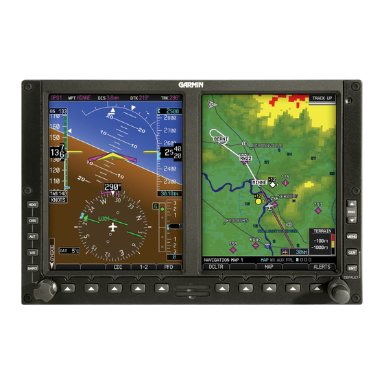
The PFD shows primary flight information, in place of traditional pitot- static and gyroscopic systems and also provides an HSI for navigation. Figure 1-2 GDU 620 PFD and MFD Figure 1-3 GDU 620 PFD and MFD with PFD on Right 190-01102-02 Rev. E Garmin G500 Pilot’s Guide... -
Page 20: Gdc 74A
Outside Air Temperature (OAT) sensor. The GDC 74A provides pressure altitude, airspeed, vertical speed, and OAT information to the G500 system. The GDC 74A communicates with the GDU 620 and GRS 77 using an ARINC 429 digital interface. -
Page 21: Gmu 44
GDC 74A. Figure 1-8 GTP 59 Temperature Probe 1.1.8 GSR 56 The GSR 56 is an Iridium satellite transceiver that supports voice telephone ® calls, aircraft position reporting, and world wide weather products. 190-01102-02 Rev. E Garmin G500 Pilot’s Guide... -
Page 22: Gdl 69/69A (Optional)
A subscription to the Sirius XM Satellite Radio service is required to enable the GDL 69/69A capability. Subscription information is available at: http://www.garmin.com/xm/. Figure 1-9 GDL 69/69A XM Satellite Radio Data Link Receiver 1.1.10... -
Page 23: Weather Radar
MFD. Figure 1-11 GWX 68 Weather Radar 1.1.12 Garmin Navigator Interface The G500 system requires connection to at least one external Garmin WAAS GPS navigator, such as the 400W/500W series or GNS 480. 1.1.13 Attitude Heading Reference System (AHRS) NOTE: Aggressive maneuvering while AHRS is not operating in normal mode may degrade AHRS accuracy. - Page 24 PFD is flagged as invalid with a red “X,” “TRK” in magenta is annunciated to the right of the Track value, and the Track value color is changed from white to magenta. Garmin G500 Pilot’s Guide 190-01102-02 Rev. E...
- Page 25 NOTE: During in-flight alignment of the AHRS, minimize aircraft maneuvering. The AHRS will align with shallow banking and pitch angles (less than 20 degrees of roll or 5 degrees of pitch). AHRS alignment may not be possible during more aggressive maneuvers. 190-01102-02 Rev. E Garmin G500 Pilot’s Guide...
-
Page 26: Secure Digital Cards
1.1.14 Secure Digital Cards The G500 System uses Secure Digital (SD) cards to load and store various types of data. For basic flight operations, SD cards are required for Terrain, Obstacle, FliteChart, SafeTaxi, and ChartView database storage as well as Jeppesen aviation and ChartView database updates. -
Page 27: System Power Up
NOTE: Refer to Section 6 for system-specific annunciations and alerts. The G500 System is integrated with the aircraft electrical system and receives power directly from electrical busses. The GDU 620 and supporting sub-systems include both power-on and continuous built-in test features that exercise the processor, memory, external inputs, and outputs to ensure safe operation. - Page 28 Navigation Map Page. When the interfaced GPS unit has acquired a sufficient number of satellites to determine a position, the aircraft’ s current position is shown on the Navigation Map Page. 1-12 Garmin G500 Pilot’s Guide 190-01102-02 Rev. E...
-
Page 29: International Geomagnetic Reference Field
Navigation Database are compared, and if the IGRF model in the GRS 77 is out of date, the user is prompted to update the IGRF model in the GRS 77. The following prompt will appear after the G500 splash screen is acknowledged on the MFD. -
Page 30: System Operation
1. Press the desired PFD mode selection key (HDG, CRS, ALT, V/S, or BARO). A window will be displayed near the upper left corner of the HSI showing the current value for that mode. 2. Turn the PFD knob to select the desired value. 1-14 Garmin G500 Pilot’s Guide 190-01102-02 Rev. E... -
Page 31: Pfd Bezel Keys
Altitude Select window. Set the Altitude Bug by turning the PFD knob after pressing the ALT key. Altitude Select Window Altitude Bug Current Altitude Barometric Setting Figure 1-17 Pressing PFD Knob Sets Altitude Select to Current Altitude 1-15 190-01102-02 Rev. E Garmin G500 Pilot’s Guide... - Page 32 Installations with GAD 43e Altitude Preselect will have a V/S popup similar to the ALT popup. For certain configurations, the selected vertical speed may be controlled by the altitude preselector and the V/S popup will show AUTO. 1-16 Garmin G500 Pilot’s Guide 190-01102-02 Rev. E...
-
Page 33: Mfd Knobs
Enter (ENT) Validates or confirms a menu selection or data entry. Clear (CLR) Erases information, cancels entries, or removes page menus. Pressing and holding the CLR key displays the Navigation Map 1 page. 1-17 190-01102-02 Rev. E Garmin G500 Pilot’s Guide... -
Page 34: Using The Soft Key Controls
To select the function indicated on the soft key label, press the soft key directly below the label. Selected Soft Key Unselected Soft Keys Soft Key Labels Soft Keys Figure 1-20 MFD Soft Key Layout 1-18 Garmin G500 Pilot’s Guide 190-01102-02 Rev. E... -
Page 35: Using The
3) Press the ENT key to select the desired option. 4) Press the CLR key or MFD knob to remove the menu and cancel the operation. No Options Options for MAP Window Figure 1-21 Page Menu Examples 1-19 190-01102-02 Rev. E Garmin G500 Pilot’s Guide... -
Page 36: System Settings
1.4.4 System Settings G500 system settings are managed from the Aux Mode System Setup Page. The following settings can be changed: • Display Brightness (Mode and Level) • Airspeed References (Glide-REF, V - V1, and V - V2) • PFD Options (Wind Vector and Nav Status) • Dual Unit Synchronization (CDI and Baro) - Dual installations only... -
Page 37: System Settings Values
Off, Style 1 - Style 4 PFD wind vector display format. Nav Status (NAV Status) Style 1 - 2 Location of GPS navigation option not data. available in all installations. Date/Time Date Time Time Format Time Offset 1-21 190-01102-02 Rev. E Garmin G500 Pilot’s Guide... - Page 38 Temperature Celsius All temperatures on PFD Fahrenheit Table 1-2 Display Units Settings (System Setup Page) More detail on changing settings is in the Section 3 - MFD Aux pages System Settings section. 1-22 Garmin G500 Pilot’s Guide 190-01102-02 Rev. E...
-
Page 39: Display Backlighting
Auto or Manual Figure 1-23 Display Brightness Adjustment 3) Turn the large MFD knob to highlight the MODE field. Turn the small MFD knob to select “AUTO” or “MANUAL.” 4) Press ENT. 1-23 190-01102-02 Rev. E Garmin G500 Pilot’s Guide... - Page 40 This page intentionally left blank 1-24 Garmin G500 Pilot’s Guide 190-01102-02 Rev. E...
-
Page 41: Primary Flight Display (Pfd)
CDI is correct and is the primary means of navigation. This is because the GDU 620 applies magnetic variation corrections for the current aircraft location, but some navigators apply magnetic variation correction for the waypoint location. 190-01102-02 Rev. E Garmin G500 Pilot’s Guide... -
Page 42: Pfd Soft Keys
The soft keys can be used to select the appropriate soft key function. Selected Soft Key Unselected Soft Key Soft Key Labels Soft Keys Soft Key Not Available Unselected Soft Key For Selection Soft Key Labels Figure 2-4 PFD Soft Key Layout Garmin G500 Pilot’s Guide 190-01102-02 Rev. E... - Page 43 The DME and SYN VIS soft keys will only be present if the system is configured for these features. BRG1 The BRG1 soft key cycles through the available bearing 1 indicator modes (NAV1, GPS1, ADF, or None). 190-01102-02 Rev. E Garmin G500 Pilot’s Guide...
- Page 44 The SYN VIS soft key is available if Synthetic Vision Technology™ is installed. It enables Synthetic Vision and displays the associated soft keys. SYN TERR The SYN TERR soft key is available if Synthetic Vision Technology™ is installed and enables synthetic terrain depiction. Garmin G500 Pilot’s Guide 190-01102-02 Rev. E...
-
Page 45: Airspeed Indicator
The trend vector is absent if the speed remains constant or if any data needed to calculate airspeed is not available due to a system failure. 190-01102-02 Rev. E Garmin G500 Pilot’s Guide... - Page 46 Normal Operating Range (Green) Flaps Operating Range (White) True Airspeed Airspeed Units Figure 2-6 Airspeed Tape Overspeed Range (Barber Pole) Overspeed Indication for Current Airspeed Caution Operating Range (yellow) Figure 2-7 Overspeed Indication Garmin G500 Pilot’s Guide 190-01102-02 Rev. E...
-
Page 47: Markings
NOTE: The actual colors and patterns of the airspeed tape may vary by installation. See your AFM/POH for more details. Figure 2-8 Typical Airspeed Tape Markings White Triangle Figure 2-9 Additional Reference Markings 190-01102-02 Rev. E Garmin G500 Pilot’s Guide... -
Page 48: Reference Speeds
Reference Marker Reference Marker Figure 2-10 Reference Speeds The labels for the reference markers may vary as configured during installation. Reference Marker Reference Marker Reference Marker Reference Marker Figure 2-11 Alternate Reference Speeds Garmin G500 Pilot’s Guide 190-01102-02 Rev. E... -
Page 49: Attitude Indicator
Slip/skid is indicated by the location of the bar relative to the pointer. One bar displacement (as shown below) is equal to one ball displacement on a traditional Slip/Skid Indicator. 190-01102-02 Rev. E Garmin G500 Pilot’s Guide... - Page 50 In an aircraft with an Attitude Indicator that has a Sky Pointer, the pointer below the roll scale shifts with the roll or bank angle of the aircraft to keep the Roll Pointer pointing towards the sky. 2-10 Garmin G500 Pilot’s Guide 190-01102-02 Rev. E...
-
Page 51: Extreme Attitude
• Ground Speed, True Airspeed, and Airspeed Units • Selected Altitude, Barometer Settings, and Selected Vertical Speed • Vertical Course Deviation Indicator • Traffic and Terrain Annunciations • Flight Director Command Bars • Radar Altimeter digital readout • Marker beacon annunciation • Fast/Slow indicator • DME field Figure 2-16 Extreme Pitch Indication 2-11 190-01102-02 Rev. E Garmin G500 Pilot’s Guide... - Page 52 Figure 2-17 Extreme Pitch Indication Figure 2-18 Extreme Pitch Indication Nose Down Nose Up Figure 2-19 Extreme Roll Indication with Display Declutter 2-12 Garmin G500 Pilot’s Guide 190-01102-02 Rev. E...
-
Page 53: Altimeter
3) Press the center of the PFD knob to set the selected altitude to the current altitude. Selected Altitude in the Selected Altitude Altitude Alerter window Altitude Trend Current Indicator Altitude Barometric Setting Figure 2-20 Altimeter 2-13 190-01102-02 Rev. E Garmin G500 Pilot’s Guide... -
Page 54: Altitude Alerting
NOTE: The aural tone when approaching the selected altitude may be configured at installation for either 200 feet or 1000 feet. The tone when deviating from the selected altitude always occurs at 200 feet. 2-14 Garmin G500 Pilot’s Guide 190-01102-02 Rev. E... -
Page 55: Changing Barometric Setting
“Minimums, minimums,” is heard one time. The text remains in yellow until the aircraft altitude is more than 50 feet above the set altitude minimum value. 2-15 190-01102-02 Rev. E Garmin G500 Pilot’s Guide... - Page 56 GDU 620 and will be synchronized on both units. Barometric Altitude Radar Altimeter 200 Foot Difference Minimums Bug Brown Band Indicating The Ground Radar Altimeter Minimums Value Radar Altimeter Value Figure 2-24 Minimums Values with a Radar Altimeter 2-16 Garmin G500 Pilot’s Guide 190-01102-02 Rev. E...
- Page 57 Section 5 - Additional Features - Charts Menu Selections. f you highlight the minimums Altitude field and hit the CLR key, it NOTE: I will turn the minimums alerting functionality off. 2-17 190-01102-02 Rev. E Garmin G500 Pilot’s Guide...
-
Page 58: Vertical Speed (V/S) Indicator
1) Press the V/S key to activate Vertical Speed mode. 2) Turn the PFD knob to change the Vertical Speed Bug. 3) Press the center of the PFD knob to set the Vertical Speed value to the current vertical speed. 2-18 Garmin G500 Pilot’s Guide 190-01102-02 Rev. E... -
Page 59: Horizontal Situational Indicator
Current Track Indicator Aircraft Symbol Turn Rate/Heading Trend Vector Course Deviation Indicator Current Heading (CDI) Lubber Line Rotating Compass Card MSG (Message) on Navigator OBS Mode Active Figure 2-26 Horizontal Situation Indicator (HSI) 2-19 190-01102-02 Rev. E Garmin G500 Pilot’s Guide... -
Page 60: Setting The Heading Bug
1) Press the HDG key to activate HDG mode. 2) Turn the PFD knob to change the Heading Bug. 3) Press the PFD knob in HDG mode to set the Heading Bug to the current heading. 2-20 Garmin G500 Pilot’s Guide 190-01102-02 Rev. E... -
Page 61: Turn Rate Indicator
If the course deviation data is not valid, the CDI is not displayed. 360º HSI GPS Level of Service Navigation Source Scale Crosstrack Error Figure 2-29 Course Deviation Indicator 2-21 190-01102-02 Rev. E Garmin G500 Pilot’s Guide... -
Page 62: Changing Cdi Sources
(two dots) while coupled to GPS, the crosstrack error (XTK) is displayed below the white aircraft symbol. VLOC Navigator 1 Navigator 1 VLOC Navigator 2 Navigator 2 Figure 2-30 CDI Navigation Sources 2-22 Garmin G500 Pilot’s Guide 190-01102-02 Rev. E... -
Page 63: Changing Cdi Course
2) Turn the PFD knob to change the Course values. 3) Press the PFD knob to set a Course that will center the CDI to the VOR station or waypoint if in GPS OBS mode. 2-23 190-01102-02 Rev. E Garmin G500 Pilot’s Guide... -
Page 64: Vertical Deviation Indicator (Vdi)
LNAV past the final approach fix (FAF), or the approach only supports LNAV service, “NO GP” is annunciated. Vertical Deviation Source Vertical Deviation Indicator Figure 2-33 Vertical Deviation Indicator (GPS Source) 2-24 Garmin G500 Pilot’s Guide 190-01102-02 Rev. E... -
Page 65: Auto-Slewing
GNS navigator and the appropriate frequency is in the active window in the navigator. The G500 will Auto-Slew the HSI course pointer for an ILS, LOC, LOC BC, LDA, or SDF approach when the steps below are completed... - Page 66 Example of activating Auto-Slewing in the G500: Course Pointer slewed to 312° for the ILS Figure 2-34 Auto-Slewing HSI with ILS Loaded and Shown with the Corresponding Approach Plate 1) The aircraft is flying vectors to final on an active ILS approach, with the appropriate approach in the GNS navigator.
-
Page 67: Supplemental Flight Data
The Bearing Information windows are displayed to the lower sides of the HSI and show: • Bearing source (GPS, NAV, or ADF) • Pointer icon (BRG1 = single line, BRG2 = double line) The Bearing Pointer is removed from the HSI if: • The NAV radio is not receiving the tuned VOR station • The NAV radio is tuned to a Localizer frequency 2-27 190-01102-02 Rev. E Garmin G500 Pilot’s Guide... - Page 68 (such as: GPS, NAV, or ADF). NOTE: The Bearing Line for navigation source 1 (BRG1) will be a single line. The Bearing Line for navigation source 2 (BRG2) will be a double line. 2-28 Garmin G500 Pilot’s Guide 190-01102-02 Rev. E...
-
Page 69: Temperature Display
PFD. The distance to the station and the Nav source used are shown. DME Information DME Hold Annunciation Selected DME Set Hold for Selected DME Figure 2-41 DME Indication 2-29 190-01102-02 Rev. E Garmin G500 Pilot’s Guide... -
Page 70: Marker Beacon Annunciations
A miscompare condition is triggered if the difference between the data reported by GDU 1 and GDU 2 exceeds the threshold described in the following table for at least one second: 2-30 Garmin G500 Pilot’s Guide 190-01102-02 Rev. E... - Page 71 An “ATTITUDE MISCOMP” annunciation is displayed over the pitch ladder if a miscompare condition exists for both pitch and roll. Pitch and Roll Miscompare Airspeed Altitude Miscompare Miscompare Pitch Miscompare Roll Miscompare Figure 2-43 Miscompare Annunciations 2-31 190-01102-02 Rev. E Garmin G500 Pilot’s Guide...
-
Page 72: Radar Altimeter
Radar Altimeter altitude value. The self-test is a wiring test to indicate communication between the GDU and the Radar Altimeter. The self-test will be cancelled after 15 seconds, the Test key is pressed again, or you leave the System Setup page. 2-32 Garmin G500 Pilot’s Guide 190-01102-02 Rev. E... -
Page 73: 2.10 Fast/Slow Indication
The Fast/Slow indication as provided from an external system is shown on the left side of the PFD along the horizon line. See your AFM for details on operation. Pointer Fast/Slow Scale Figure 2-48 Fast/Slow Scale and Pointer 2-33 190-01102-02 Rev. E Garmin G500 Pilot’s Guide... -
Page 74: 2.11 Pfd Display Units
The PFD display units may be set to standard or metric units by the installer. The MFD display units may still be selected by the user in the System Setup page of Aux mode. 2-34 Garmin G500 Pilot’s Guide 190-01102-02 Rev. E... -
Page 75: Multi-Function Display (Mfd)
GPS navigator. The leg of the active flight plan currently being flown is shown as a magenta line on the navigation map. The other legs are shown in white. 190-01102-02 Rev. E Garmin G500 Pilot’s Guide... -
Page 76: Functional Display Map
Split Screen (opt) Wx Data 3 (opt) Charts (opt) XM Radio (opt) Traffic (opt) Weather Radar (opt) Terrain (TAWS/SVT opt) System Status Pos Report (opt) Iridium Phone (opt) Figure 3-2 MFD Page Groups Garmin G500 Pilot’s Guide 190-01102-02 Rev. E... -
Page 77: Mfd Soft Key Map
Below Mode CAPTURE Normal PS15 Control Above System Status Horizon BACK Unrest Vertical Terrain DBASE Back View Position Reporting Send Iridium Telephone Inhibit Dial Answer Hang Up Keys Figure 3-3 MFD Soft Keys 190-01102-02 Rev. E Garmin G500 Pilot’s Guide... -
Page 78: Navigation Map
Traffic Icons Plan Leg with Relative Aircraft Symbol Altitude and Trend (Present Position) Indicator Terrain Symbol Terrain Data Scale Indicates Terrain is Displayed Map Range Page Location Page Name Figure 3-4 MFD Map Description Garmin G500 Pilot’s Guide 190-01102-02 Rev. E... -
Page 79: Default Navigation Map Page
500 feet to 2000 NM. When the map range is decreased to a point that exceeds the capability of the GDU 620 to accurately represent the map, a magnifying glass icon is shown to the left of the map range. 190-01102-02 Rev. E Garmin G500 Pilot’s Guide... -
Page 80: Decluttering Map Pages
Each successive press of the DCLTR soft key will toggle through the declutter levels. Features marked with a “•” are shown at the indicated Declutter Level. NOTE: Traffic is automatically decluttered from Nav Map pages when the map scale is above 150 NM. Garmin G500 Pilot’s Guide 190-01102-02 Rev. E... - Page 81 • • Traffic Labels • • • Class C Airspace • • Water Detail • • • • Active FPL Legs • • • • Table 3-1 Features Shown at Each Decluttering Level 190-01102-02 Rev. E Garmin G500 Pilot’s Guide...
-
Page 82: Panning
2) Turn the large MFD knob to move the cursor horizontally. Turn the small MFD knob to move the cursor vertically. 3) Press the small MFD knob again to cancel panning. The display will return to the previous map view. Garmin G500 Pilot’s Guide 190-01102-02 Rev. E... -
Page 83: Selecting Items On The Map
3) Press the INFO soft key (if available) to view more information about the highlighted feature. 4) Press the WX soft key (if available) to view TAF and METAR information. 5) Press the small MFD knob again to return to panning. 190-01102-02 Rev. E Garmin G500 Pilot’s Guide... -
Page 84: Measuring Distances
Distance and Bearing Between Start and End Points Ending Reference Point position Ending Reference Point Starting Reference Point Figure 3-12 Bearing/Distance Measurement 3-10 Garmin G500 Pilot’s Guide 190-01102-02 Rev. E... -
Page 85: Customizing Navigation Map
Figure 3-14 Navigation Map Page Menu Map Group Selection 4) Press the small MFD knob to return to the Navigation Map Page. 3-11 190-01102-02 Rev. E Garmin G500 Pilot’s Guide... - Page 86 Lat/Lon Off/Range Viewing Range Field of On/Off View** * - shown if the Aviation database is current. ** - shown if Synthetic Vision is available. Table 3-2 Navigation Map Page Menu Selections 3-12 Garmin G500 Pilot’s Guide 190-01102-02 Rev. E...
-
Page 87: Map Feature Options
4) Press the small MFD knob to cancel selection or to end editing and return to the Navigation Map page or turn the large MFD knob to the next option. Map Orientation The Orientation option sets the orientation of the Navigation Map. Figure 3-17 Navigation Map Orientation 3-13 190-01102-02 Rev. E Garmin G500 Pilot’s Guide... - Page 88 3) Press ENT to accept the displayed value. The next option will be highlighted. 4) Press the small MFD knob to cancel selection or to end editing and return to the Navigation Map page or turn the large MFD knob to the next option. 3-14 Garmin G500 Pilot’s Guide 190-01102-02 Rev. E...
-
Page 89: Auto Zoom
3) Press ENT to accept the displayed value. The next option will be highlighted. 4) Press the small MFD knob to cancel selection or to end editing and return to the Navigation Map page or turn the large MFD knob to the next option. 3-15 190-01102-02 Rev. E Garmin G500 Pilot’s Guide... - Page 90 Track and the distance the aircraft will travel in the selected time. Track Vector Aircraft Present Position Figure 3-21 Navigation Map Track Vector 3-16 Garmin G500 Pilot’s Guide 190-01102-02 Rev. E...
- Page 91 The Wind Vector option when turned on will show a box in the top right corner of the MFD indicating the wind direction and speed. Wind Direction Wind Speed Figure 3-23 Navigation Map Wind Vector Display Figure 3-24 Navigation Map Wind Vector Selection 3-17 190-01102-02 Rev. E Garmin G500 Pilot’s Guide...
- Page 92 (25% of the map range). Range Ring Radius Range Ring with Compass Rose Figure 3-25 Navigation Map Range Ring Figure 3-26 Navigation Map Range Ring Selection 3-18 Garmin G500 Pilot’s Guide 190-01102-02 Rev. E...
- Page 93 Traffic, Land Data, Terrain, and Obstacles will still be displayed even with Topo Data turned off. Topo Data Off Topo Data On Figure 3-27 Navigation Map Topo Data Figure 3-28 Navigation Map Topo Data Selection 3-19 190-01102-02 Rev. E Garmin G500 Pilot’s Guide...
- Page 94 Displayed on the Map Sky Indication Range of Topography Current Aircraft Altitude Displayed on the Map Current Ground Level Indication Figure 3-29 Navigation Map Topo Scale Figure 3-30 Navigation Map Topo Scale Selection 3-20 Garmin G500 Pilot’s Guide 190-01102-02 Rev. E...
- Page 95 Terrain has been selected. Terrain Data On Terrain Data Off Terrain Data Terrain Elevation Scale Terrain Data Icon Figure 3-31 Navigation Map Terrain Data Figure 3-32 Navigation Map Terrain Data Selection 3-21 190-01102-02 Rev. E Garmin G500 Pilot’s Guide...
- Page 96 The Terrain Scale option selects whether the Terrain Scale is shown on the Navigation Map. The Terrain scale will be located on the right side of the display. Figure 3-33 Navigation Map Terrain Scale Selection Figure 3-34 Navigation Map Terrain Scale 3-22 Garmin G500 Pilot’s Guide 190-01102-02 Rev. E...
- Page 97 Terrain more than 1000 ft below the aircraft altitude (Black) Figure 3-36 TERRAIN Altitude/Color Correlation Obstacles Within 1000 feet of Aircraft Obstacles Within 100 feet of Aircraft or Above Figure 3-37 Navigation Map Obstacle Data 3-23 190-01102-02 Rev. E Garmin G500 Pilot’s Guide...
- Page 98 Figure 3-38 Navigation Map Obstacle Data Selection 3-24 Garmin G500 Pilot’s Guide 190-01102-02 Rev. E...
- Page 99 Lat/Lon lines will not be shown. In the figure below where 200 NM is selected, Lat/Lon lines will be shown at map ranges of 200 NM and lower. Figure 3-39 Navigation Map Lat/Lon Selection Lat/Lon Reference Information Figure 3-40 Navigation Map Lat/Lon Information 3-25 190-01102-02 Rev. E Garmin G500 Pilot’s Guide...
-
Page 100: Field Of View
Field of View The PFD Field of View used for the Garmin Synthetic Vision Technology (SVT™) option (when enabled) can be represented on the MFD Navigation Map Page lateral image. Two dashed lines forming a V-shape in front of the aircraft symbol on the MFD, represent the forward viewing area shown on the PFD. -
Page 101: Weather Feature Options (Optional)
Lightning Viewing range. Weather is an optional feature that requires a GDL 69/69A and an XM WX Satellite Weather subscription, or other weather product (such as GFDS). Figure 3-43 Navigation Map Page Menu Figure 3-44 Navigation Map Page Menu Weather Group Selection 3-27 190-01102-02 Rev. E Garmin G500 Pilot’s Guide... - Page 102 Movement will not be shown. In the example below where 150 NM is selected, the NEXRAD Cell Movement will be shown at map ranges of 150 NM and lower. Figure 3-46 NEXRAD Cell Movement Selection 3-28 Garmin G500 Pilot’s Guide 190-01102-02 Rev. E...
- Page 103 In the figure below where 200 NM is selected, Lightning symbols will be shown at map ranges of 200 NM and lower. Figure 3-48 Lightning Viewing Range Selection 3-29 190-01102-02 Rev. E Garmin G500 Pilot’s Guide...
-
Page 104: Traffic Feature Options (Optional)
Coverage is limited to specific areas as shown in the Airmen’ s Information Manual (AIM). TAS data comes from a TAS unit such as a Garmin GTS 800 or 820, Skywatch 497, KTA 810, or other unit. Coverage follows the aircraft. In the Navigation Map page setup you can select the maximum range at which traffic symbols are shown. -
Page 105: Aviation Feature Options
The Aviation group selection from the Map Setup Page Menu allows you to customize the display of SafeTaxi information, Runway Extensions, Intersection/ NDB locations, VOR locations, and TFR icons on the Navigation Map. Figure 3-51 Navigation Map Page Menu Aviation Group Selection 3-31 190-01102-02 Rev. E Garmin G500 Pilot’s Guide... - Page 106 Runway Extensions will be shown at and below the selected map range. When Off is selected, Runway Extensions will not be shown. Figure 3-53 Navigation Map Runway Extension Selection 3-32 Garmin G500 Pilot’s Guide 190-01102-02 Rev. E...
- Page 107 When Off is selected, the information will not be shown. In the example below where 150 NM is selected, VOR information will be shown at map ranges of 150 NM and lower. Figure 3-55 Navigation Map VOR Viewing Range Selection 3-33 190-01102-02 Rev. E Garmin G500 Pilot’s Guide...
- Page 108 In the example below where 200 NM is selected, Class B/TMA airspace information will be shown at map ranges of 200 NM and lower. Figure 3-56 Navigation Map Class B/TMA Viewing Range Selection 3-34 Garmin G500 Pilot’s Guide 190-01102-02 Rev. E...
- Page 109 In the example below where 200 NM is selected, Class C/TCA airspace information will be shown at map ranges of 200 NM and lower. Figure 3-57 Navigation Map Class C/TCA Viewing Range Selection 3-35 190-01102-02 Rev. E Garmin G500 Pilot’s Guide...
- Page 110 In the example below where 150 NM is selected, Class D airspace information will be shown at map ranges of 150 NM and lower. Figure 3-58 Navigation Map Class D Viewing Range Selection 3-36 Garmin G500 Pilot’s Guide 190-01102-02 Rev. E...
- Page 111 In the example below where 200 NM is selected, Restricted airspace information will be shown at map ranges of 200 NM and lower. Figure 3-59 Navigation Map Restricted Airspace Viewing Range Selection 3-37 190-01102-02 Rev. E Garmin G500 Pilot’s Guide...
- Page 112 In the example below where 200 NM is selected, MOA airspace information will be shown at map ranges of 200 NM and lower. Figure 3-60 Navigation Map MOA (Military) Viewing Range Selection 3-38 Garmin G500 Pilot’s Guide 190-01102-02 Rev. E...
- Page 113 In the example below where 200 NM is selected, Other/ADIZ airspace information will be shown at map ranges of 200 NM and lower. Figure 3-61 Navigation Map Other/ADIZ Viewing Range Selection 3-39 190-01102-02 Rev. E Garmin G500 Pilot’s Guide...
- Page 114 In the example below where 500 NM is selected, TFR information will be shown at map ranges of 500 NM and lower. This optional feature requires an active data link receiver. Figure 3-62 Navigation Map TFR Viewing Range Selection 3-40 Garmin G500 Pilot’s Guide 190-01102-02 Rev. E...
- Page 115 The Airways option allows you to select the airways that are shown on the Navigation Map. All, Low only, and Hi only Airways may be selected. When Off is selected, airways will not be shown. Figure 3-63 Airways Selection 3-41 190-01102-02 Rev. E Garmin G500 Pilot’s Guide...
-
Page 116: Split Screen (Optional)
3) To select the other external video source, press the MENU key. Selected Video Source Figure 3-65 Aux Mode System Setup Page Menu 4) Turn the large or small MFD knobs to highlight the Video selection and then press ENT 3-42 Garmin G500 Pilot’s Guide 190-01102-02 Rev. E... -
Page 117: Aux Mode Pages
The Aux mode provides pages for System Setup, XM Information (if installed), and system Status. 3.4.1 System Settings G500 system settings are managed from the Aux Mode System Setup Page. The following settings can be changed: • Display Brightness (Mode and Level) • Airspeeds (Glide-REF, V... -
Page 118: Display Brightness
3) If the Level was changed, Manual will be selected. Press the cursor to save the settings. If you press ENT the Mode setting will be highlighted. 4) With the Mode value highlighted, turn the small MFD knob to select Auto or Manual and then press ENT 3-44 Garmin G500 Pilot’s Guide 190-01102-02 Rev. E... -
Page 119: Airspeed Reference Marks
NOTE: When power is cycled, the Airspeed Reference values are reset. During preflight, the Airspeed Reference values should be checked and set appropriately for the current aircraft configuration and performance. Figure 3-70 Airspeed References shown on PFD when activated 3-45 190-01102-02 Rev. E Garmin G500 Pilot’s Guide... -
Page 120: Pfd Options - Wind Vector
3) When a Wind Vector style is selected, a Wind Vector box with the chosen style will be displayed to the left of the HSI on the PFD. When OFF is selected, the Wind Vector box will not be displayed. 3-46 Garmin G500 Pilot’s Guide 190-01102-02 Rev. E... -
Page 121: Pfd Options - Nav Status
Figure 3-72 Nav Status Style 3) After the Nav Status style is selected, the chosen style will be displayed on the PFD. NOTE: Nav Status option is not available for all installations. 3-47 190-01102-02 Rev. E Garmin G500 Pilot’s Guide... -
Page 122: Synchronization (Dual Installations Only)
The following information is always synchronized between both GDU 620 units: • Selected Altitude • Selected Heading • Selected Course • Selected Vertical Speed • Airspeed Bug Values • Airspeed Color Band Values • System Pressure Units • System Temperature Units 3-48 Garmin G500 Pilot’s Guide 190-01102-02 Rev. E... - Page 123 GDU 620. In a dual GDU 620 system, the CDI keys in the navigator are disabled. 3-49 190-01102-02 Rev. E Garmin G500 Pilot’s Guide...
-
Page 124: Date And Time
ENT. When Local 12 or 24 hr mode is selected, the Time Offset value will then be highlighted. 3) Turn the small MFD knob to select the desired offset and then press ENT. 3-50 Garmin G500 Pilot’s Guide 190-01102-02 Rev. E... -
Page 125: Mfd Display Units
2) Turn the small MFD knob to select Imperial, Metric, or Nautical and then press ENT. The Altitude and Vertical Speed units selection will now be highlighted. 3) Turn the small MFD knob to select Feet or Meters and then press ENT. 3-51 190-01102-02 Rev. E Garmin G500 Pilot’s Guide... -
Page 126: System Display Units
The Barometric Pressure Setting value will now be highlighted. When True is selected, a "T" will appear to the right of the heading value on the PFD. Figure 3-79 Barometric Setting System Display Units 3-52 Garmin G500 Pilot’s Guide 190-01102-02 Rev. E... -
Page 127: Sirius Xm Satellite Radio Xm Information (Optional)
The Aux mode XM Information page displays information about the Sirius XM Satellite radios, service, and products when the GDL 69/69A is installed and the Sirius XM Satellite Radio service is activated. Figure 3-81 XM Information 3-53 190-01102-02 Rev. E Garmin G500 Pilot’s Guide... -
Page 128: Sirius Xm Satellite Radio Xm Entertainment Radio (Optional)
2) Turn the small MFD knob to the XM Radio page. Figure 3-82 XM Entertainment Radio A description of Sirius XM Satellite Radio audio entertainment is provided in Section 5 - Additional Features. 3-54 Garmin G500 Pilot’s Guide 190-01102-02 Rev. E... -
Page 129: System Status
LRUs. Pertinent information on all system databases is also displayed. Active LRUs are indicated by green check marks; failed LRUs by red “X’ s .” Failed LRUs should be noted and a service center or Garmin-authorized dealer informed. LRU Info Window Database Window... -
Page 130: External Video (Optional)
1) Touch the Video 1 soft key to select Video 1 source for viewing and setup. 2) Touch the Video 2 soft key to select Video 2 source for viewing and setup. 3-56 Garmin G500 Pilot’s Guide 190-01102-02 Rev. E... -
Page 131: Zoom
3) The Current value for Brightness will be selected. Use the following directions for each value. Figure 3-85 External Video Setup 4) After selecting the desired settings, press the small MFD knob or the Setup soft key to exit editing. 3-57 190-01102-02 Rev. E Garmin G500 Pilot’s Guide... -
Page 132: Brightness Adjustment
Figure 3-87 External Video Contrast Adjustment 3) After selecting the desired setting, turn the large MFD knob to highlight the next value or press the small MFD knob to exit editing. 3-58 Garmin G500 Pilot’s Guide 190-01102-02 Rev. E... -
Page 133: Restore Defaults
Saturation values to their original settings. 1) While viewing the External Video page, press the MENU key. Figure 3-89 Restore Video Defaults Menu Selection 2) "Restore Defaults" will be highlighted. Press the ENT key. 3-59 190-01102-02 Rev. E Garmin G500 Pilot’s Guide... -
Page 134: Position Reporting (Optional)
When the Standard reporting type is used, the Position Reporting Period may be set to Off or Automatic. The Automatic Position Reporting Period can be set to intervals of 2 to 60 minutes. 3-60 Garmin G500 Pilot’s Guide 190-01102-02 Rev. E... - Page 135 7) With the Standard Reporting Type, the reporting period may be manually overridden by pressing the SEND soft key to send data. SEND Soft Key Label SEND Soft Key Figure 3-93 Press SEND to Override the Reporting Period 3-61 190-01102-02 Rev. E Garmin G500 Pilot’s Guide...
- Page 136 Automatic Flight Following (AFF) The G500 system, when combined with a GSR 56 Iridium datalink, can send position reports that contain data as required by the U.S. Government Automated Flight Following system. The GSR 56 account will allow configuration to forward data to the Automated Flight Following system.
-
Page 137: Iridium Phone Operation (Optional)
Optional satellite telephone operation is available through the Iridium ® satellite system that is interfaced through the Garmin GSR 56. CAUTION: When interfaced with a GSR56 Iridium transceiver only one SD card may be present in the GDU620 and it must be in the lower slot. - Page 138 3) Turn the small MFD knob to highlight the desired selection. Figure 3-96 Select Call Suppression 4) Press the ENT key. Press the small MFD knob again to cancel the selection cursor. 3-64 Garmin G500 Pilot’s Guide 190-01102-02 Rev. E...
-
Page 139: Managing The Phone Book
4) Turn the small MFD knob to select the first character of the name and then turn the large MFD knob to select the next character. When the name is complete, press the ENT key. Phone Book Entry Name Catalog Figure 3-98 Phone Book Name Entry 3-65 190-01102-02 Rev. E Garmin G500 Pilot’s Guide... - Page 140 When the number is complete, press the ENT key. Phone Book Catalog Entry Number Press To Use Keys For Number Entry Figure 3-99 Phone Book Number Entry 2) Press the small MFD knob again to cancel the selection cursor. 3-66 Garmin G500 Pilot’s Guide 190-01102-02 Rev. E...
- Page 141 2) Turn the small MFD knob to display the contents of the Phone Book Catalog and highlight the desired entry. Selected Phone Book Catalog Entry Figure 3-104 Selected Phone Book Catalog Entry 3-67 190-01102-02 Rev. E Garmin G500 Pilot’s Guide...
-
Page 142: Phone Volume
2) Turn the small MFD knob to set the desired volume level. 3) Press the ENT key. Press the small MFD knob again to cancel the selection cursor. 3-68 Garmin G500 Pilot’s Guide 190-01102-02 Rev. E... -
Page 143: Making A Phone Call
1) While viewing the Iridium Phone page, enter a phone number or select one from the Phone Book catalog. 2) Press the DIAL key. 3) After completing the call, press the HANG UP key. 3-69 190-01102-02 Rev. E Garmin G500 Pilot’s Guide... -
Page 144: Answering A Phone Call
Press the HANG UP soft key to end the call. Press the VOL - or VOL + keys to adjust the call volume. Figure 3-108 Connected Call Pop-Up 3-70 Garmin G500 Pilot’s Guide 190-01102-02 Rev. E... -
Page 145: Flight Plan
DTK, Distance, and ETA Digital Chart from the Previous Leg Available For Waypoint Graphic METARs Current Leg Flight Plan Legs Baro Minimums Window Active Leg Window Figure 3-109 Flight Page 1 (Active Flight Plan) 3-71 190-01102-02 Rev. E Garmin G500 Pilot’s Guide... -
Page 146: Active Flight Plan Detail
Figure 3-110 Active Flight Plan Page Menu Option Selection 3) Turn the large MFD knob to highlight the field you wish to change. Figure 3-111 Active Flight Plan Page Menu Change Fields Option Selection 3-72 Garmin G500 Pilot’s Guide 190-01102-02 Rev. E... -
Page 147: Setting The Altitude Minimums Alerter
Figure 3-113 Minimums Source Selection 3) Turn the large MFD knob to highlight the Altitude Minimums value. Turn the large and small MFD knobs to change the Altitude Minimums value. Figure 3-114 Minimums Altitude Selection 3-73 190-01102-02 Rev. E Garmin G500 Pilot’s Guide... -
Page 148: Waypoint Information Page
Rwy/Freq Soft Key Airport Directory Soft Key Wpt Weather Info Soft Key Figure 3-115 Flight Plan Waypoint Information Page NOTE: Waypoint information is shown on the second page of the Flight Plan page group. 3-74 Garmin G500 Pilot’s Guide 190-01102-02 Rev. E... -
Page 149: Selecting A Waypoint
Figure 3-117 Waypoint Category Selection 3) Turn the small MFD knob to show FPL, NRST, or RECENT. 4) Turn the large MFD knob to highlight the desired airport, and then press ENT. 3-75 190-01102-02 Rev. E Garmin G500 Pilot’s Guide... -
Page 150: Waypoint Information Detail
Frequency window, a scroll bar is shown on the right side of the window when more frequencies are available. Facility Information Window Runway Information Window Airport Frequency Window Figure 3-118 Flight Plan Waypoint Info Detail 3-76 Garmin G500 Pilot’s Guide 190-01102-02 Rev. E... - Page 151 3) Use the large MFD knob to highlight the field you wish to change and use the small MFD knob to change the value. 4) Press the ENT key to save the selected value or press the small MFD knob to cancel editing. 3-77 190-01102-02 Rev. E Garmin G500 Pilot’s Guide...
- Page 152 RWY/FREQ soft key to view information about the waypoint and then press the small MFD knob to activate the cursor. 2) Turn the small MFD knob to scroll through the available frequencies. 3) Press the small MFD knob to exit. 3-78 Garmin G500 Pilot’s Guide 190-01102-02 Rev. E...
-
Page 153: Airport Directory
3) Use the small or large MFD knob to scroll through the information. 4) Press the small MFD knob to deactivate the cursor. Press the APT DIR soft key again to return to the Waypoint Information page. 3-79 190-01102-02 Rev. E Garmin G500 Pilot’s Guide... -
Page 154: Waypoint Weather Information (Optional)
WX soft key to view weather information for the waypoint. 2) Use the small MFD knob or the large MFD knob to scroll through the available information. 3) Press the small MFD knob to return to the main Flight Plan page. 3-80 Garmin G500 Pilot’s Guide 190-01102-02 Rev. E... -
Page 155: Charts Page (Optional)
Charts Page (Optional) Charts, when installed, are available in the Flight Plan page group. ChartView is an optional feature that requires enablement by a Garmin dealer. 1) Turn the large MFD knob to the Flight Plan page group. 2) Turn the small MFD knob to the Charts page. -
Page 156: Viewing Charts
NOTE: When Panning mode is active, scroll bars will be shown on the right side and bottom of the display. 3) Press the small MFD knob to cancel the scroll bars and exit panning. Scroll Bars Figure 3-125 Chart Scroll Bars (Charts) 3-82 Garmin G500 Pilot’s Guide 190-01102-02 Rev. E... -
Page 157: Selecting A New Chart By Airport
7) With ChartView only and when available for the selected chart, more detail is available. Press the Detail key to view detailed views of the current chart. Press the Header, Plan, Profile, or Minimums keys to view detailed sections for the chart for those topics. 3-83 190-01102-02 Rev. E Garmin G500 Pilot’s Guide... -
Page 158: Selecting A New Chart By Fpl, Nrst, Or Recent
6) If “Auto” is selected, turn the large MFD knob to highlight the Display Level Brightness value. Turn the small MFD knob to change the value and then the ENT key to save the selected value. 3-84 Garmin G500 Pilot’s Guide 190-01102-02 Rev. E... -
Page 159: Hazard Avoidance
HAZARD AVOIDANCE The G500 hazard avoidance features are designed to provide advisory information of potential hazards to flight safety associated with weather, terrain, and air traffic. This section is divided into the following groups: Terrain Avoidance • Terrain Proximity • Garmin Terrain-SVT™ (Optional) Traffic Avoidance • Traffic Advisory System (Optional) - Page 160 Terrain-SVT alerting has occurred. GNS/GTN TAWS may be provided by a GNS 500WT-series or GTN-series navigator with TAWS. The GNS/GTN TAWS must be interfaced to the G500 as GPS 1. In all configurations, any terrain information or alerts displayed on the MFD are generated by the G500.
-
Page 161: Terrain Scale
Table 4-2 Terrain Scale Color Codes Terrain Proximity Garmin Terrain is a non-TSO-C151b-certified terrain awareness system provided as a standard feature of GDU 620 to increase situational awareness and help reduce controlled flight into terrain (CFIT). Terrain may be displayed on the Map page group Navigation Map and Terrain pages. -
Page 162: Displaying Terrain Proximity
North Indication Altitude Information Range Rings Ownship Symbol at Present Position Terrain Altitude Legend Page Name 120° 360° Range Ring Selection Selection Figure 4-2 Terrain Page with Aviation Data Displayed and 360° View Garmin G500 Pilot’s Guide 190-01102-02 Rev. E... -
Page 163: Terrain Proximity Page Display On A Navigation Map Page
1) Press the VIEW soft key to show the 360 and ARC soft keys. 2) Press the 360 or Arc soft key. Press MENU and the with the View Arc or View 360° selection highlighted press ENT. 190-01102-02 Rev. E Garmin G500 Pilot’s Guide... -
Page 164: Terrain Proximity Page Aviation Data
1) While viewing the Terrain page of the MAP page group, press MENU for Map selections to hide or show aviation data overlay on the Terrain page. Figure 4-7 Show/Hide Aviation Data on the Terrain Page Garmin G500 Pilot’s Guide 190-01102-02 Rev. E... - Page 165 2) Press ENT to save the highlighted value. Figure 4-8 Terrain Page with Aviation Data Displayed and 120° Arc View Figure 4-9 Navigation Map Page with Terrain Data Displayed 190-01102-02 Rev. E Garmin G500 Pilot’s Guide...
-
Page 166: Terrain Proximity Limitations
The displayed information should never be understood as being all- inclusive. WARNING: The data contained in the Terrain databases comes from government agencies. Garmin accurately processes and cross-validates the data but cannot guarantee the accuracy and completeness of the data. 4.3.3... -
Page 167: External Taws
Altitude Tape on the PFD. A new annunciation will flash for approximately five seconds. • TAWS annunciations can only be received from the #1 GPS unit. • If the Garmin GPS/TAWS is not available and Terrain-SVT is enabled, the G500 Terrain-SVT will generate PFD text alerts and aural callouts. An advisory message will indicate when reversion to Terrain-SVT alerting has occurred. Figure 4-10 TAWS Annunciations from a GNS/GTN TAWS 190-01102-02 Rev. -
Page 168: Garmin Terrain-Svt™ (Optional)
Garmin Terrain-SVT™ (Optional) Garmin Terrain-SVT™ refers to a subset of Class B TAWS that meets the terrain alerting requirements outlined in Section 7.b of AC 23-26. Terrain-SVT is a subset of Class B TAWS that provides a Class B TAWS FLTA functionality with visual alerting and aural alerting. -
Page 169: Garmin Terrain-Svt™ Page 120° Arc Or 360° Rings
4.5.1.1 Garmin Terrain-SVT™ Page 120° Arc or 360° Rings Select the 120º Arc or 360º rings overlay for the Terrain page with either the 360/Arc soft keys or from the Page Menu. Figure 4-11 Terrain-SVT 360 and Arc Views 1. Press VIEW and then the 360 or Arc soft key. -
Page 170: Garmin Terrain-Svt™ Page Aviation Data
4.5.1.2 Garmin Terrain-SVT™ Page Aviation Data Select the display of Aviation data on the Garmin Terrain-SVT page. The Page Menu selections allow you to hide or show aviation data overlay on the Terrain or the Map Setup options for the Navigation Map pages. -
Page 171: Synthetic Vision Alerts And Annunciations
SVT page is not displayed at the time, a pop-up alert appears on the MFD. To acknowledge the pop-up alert: Press the CLR key (returns to the currently viewed page) Press the ENT key (accesses the Terrain-SVT Page) Figure 4-15 Terrain-SVT Advisory Pop-Up on the MFD 4-13 190-01102-02 Rev. E Garmin G500 Pilot’s Guide... - Page 172 “Caution, Terrain, Terrain” (RTC-C, ITI-C) FLTA Terrain Warning “Warning, Terrain, Terrain” (RTC-W, ITI-W) FLTA Obstacle Caution “Caution, Obstacle, Obstacle” (ROC-C, IOI-C) FLTA Obstacle Warning “Warning, Obstacle, Obstacle” (ROC-W, IOI-W) Table 4-4 Terrain-SVT Alerts Summary 4-14 Garmin G500 Pilot’s Guide 190-01102-02 Rev. E...
-
Page 173: Tas Traffic (Optional)
TAS refers to an active Traffic Advisory System that may be optionally displayed on the PFD and/or MFD. The TAS is installed separately from the G500 system. There are variations in performance and control among the various G500-compatible TAS systems. Refer to the appropriate TAS documentation for detailed information on the operation of the TAS system. -
Page 174: Switching From Standby Mode To Operating Modes
2) To switch to Standby Mode from the Traffic Page, select the STANDBY soft key. NOTE: Not all TAS systems can be controlled from the G500. The Operate/ Standby soft keys may not be displayed. An alert will be generated when Standby is selected and the aircraft is in the air. -
Page 175: Range Ring
Normal -2700 ft to 2700 ft Above -2700 ft to 9700 ft Unrestricted All Traffic Shown Table 4-5 Displayed Traffic Range NOTE: Traffic Advisories (TAs) are always displayed, regardless of altitude mode. 4-17 190-01102-02 Rev. E Garmin G500 Pilot’s Guide... -
Page 176: Tas Symbology
Closing rate, distance, and vertical separation meet TA criteria. A Traffic Advisory that is beyond the selected display range is indicated by a half TA symbol at the edge of the screen at the relative bearing of the intruder. 4-18 Garmin G500 Pilot’s Guide 190-01102-02 Rev. E... -
Page 177: Traffic System Status
Data is not being received from the TAS unit Data is being received from the TAS unit, but the DATA FAILED unit is self-reporting a failure FAILED Incorrect data format received from the TAS unit Table 4-8 TAS Failure Annunciations 4-19 190-01102-02 Rev. E Garmin G500 Pilot’s Guide... - Page 178 NO TRFC DATA Data is not being received from the TAS unit *Shown as symbol on Traffic Map Page **Shown in center of Traffic Map Page Table 4-9 TAS Traffic Status Annunciations 4-20 Garmin G500 Pilot’s Guide 190-01102-02 Rev. E...
-
Page 179: Traffic Pop-Up
NOTE: The traffic pop-up will not appear when your aircraft is on the ground. Press ENT to go directly to the Traffic page. Press CLR to return to the previously viewed page. Traffic Pop-Up Figure 4-17 Traffic Pop-Up 4-21 190-01102-02 Rev. E Garmin G500 Pilot’s Guide... -
Page 180: Tis Traffic (Optional)
Page. When the aircraft is on the ground, TIS automatically enters Standby Mode. Once the aircraft is airborne, TIS switches from Standby to Operating Mode and the GDU 620 begins to display traffic information. 4-22 Garmin G500 Pilot’s Guide 190-01102-02 Rev. E... -
Page 181: Displaying Traffic On The Traffic Map Page
Operating Mode Traffic Advisory, Aircraft is 1200 feet above, climbing, and moving away Proximity Advisory, Aircraft is 5000 feet below, descending and moving away Figure 4-18 Traffic Map Page - TIS 4-23 190-01102-02 Rev. E Garmin G500 Pilot’s Guide... -
Page 182: Tis Symbology
(for speeds greater than 500 fpm in either direction) to the right of the target symbol. Traffic symbols for aircraft without altitude reporting capability appear without altitude separation or climb/descent information. 4-24 Garmin G500 Pilot’s Guide 190-01102-02 Rev. E... -
Page 183: Tis Limitations
4.7.3 TIS Limitations NOTE: This section on TIS Limitations is not comprehensive. Garmin recommends the user review the TIS Limitations section of the Aeronautical Information Manual, Section 1-3-5. TIS is NOT intended to be used as a collision avoidance system and does not relieve the pilot of responsibility to “see and avoid”... - Page 184 Garmin is not responsible for Mode S geographical coverage. Operation of the ground stations is the responsibility of the FAA. Refer to the Aeronautical Information Manual for a Terminal Mode S Radar Site Map covering the U.S. NOTE: TIS will be unavailable at low altitudes in many areas of the U.S., particularly in mountainous regions.
-
Page 185: Tis Alerts
• Traffic or requesting aircraft is below radar coverage. In flat terrain, the coverage extends from about 3000 feet upward at 55 miles. Terrain and obstacles around the radar site can further decrease radar coverage in all directions. • Traffic does not have an operating transponder. 4-27 190-01102-02 Rev. E Garmin G500 Pilot’s Guide... -
Page 186: Traffic Pop-Up
Mode in the air. If TIS fails the power up test, an annunciation is shown in the center of the Traffic Map Page. NOTE: An alert will be generated when Standby is selected and the aircraft is in the air. 4-28 Garmin G500 Pilot’s Guide 190-01102-02 Rev. E... -
Page 187: Switching Between Tis Operating Modes
The transponder has failed UNAVAILABLE TIS is unavailable or out of range * Contact a service center or Garmin dealer for corrective action Table 4-11 TIS Failure Annunciations The traffic mode is annunciated in the upper left corner of the Traffic Map Page. - Page 188 Traffic has not been detected TRFC UNAVAIL The traffic service is unavailable or out of range *Shown as symbol on Traffic Map Page **Shown in center of Traffic Map Page Table 4-13 TIS Traffic Status Annunciations 4-30 Garmin G500 Pilot’s Guide 190-01102-02 Rev. E...
-
Page 189: Xm Wx Satellite Weather (Optional)
“Weather Setup” option. Press ENT Figure 4-20 Weather Page Menu Options 2) With the Data Link Setup Menu displayed, turn the Large MFD knob to select the desired item and press ENT. 4-31 190-01102-02 Rev. E Garmin G500 Pilot’s Guide... - Page 190 4) Press ENT to save a selection. 5) Turn the large MFD knob to the next desired option press the small MFD knob to cancel and return to the XM WX Satellite Weather Data Link Map Page. 4-32 Garmin G500 Pilot’s Guide 190-01102-02 Rev. E...
-
Page 191: Xm Wx Weather Symbols And Product Age
WARNING: Do not use data link weather information for maneuvering in, near, or around areas of hazardous weather. Information contained within data link weather products may not accurately depict current weather conditions. 4-33 190-01102-02 Rev. E Garmin G500 Pilot’s Guide... - Page 192 Top Mutually Exclusive) XM Lightning Cell Movement 1.25 SIGMETs / AIRMETs METARs City Forecast Surface Analysis Freezing Levels Winds Aloft County Warnings Cyclone Warnings Table 4-15 Weather Product Symbols and Data Timing 4-34 Garmin G500 Pilot’s Guide 190-01102-02 Rev. E...
- Page 193 Winds Aloft is not displayed. Instead, the generation time for these is displayed. Symbol Description Flood Severe Thunderstorm Tornado Sunny Part Sun Cloudy Rainy T-Storm Snow Windy Foggy Haze High/Low Temp Table 4-16 Weather Symbols 4-35 190-01102-02 Rev. E Garmin G500 Pilot’s Guide...
-
Page 194: Weather Legends
XM Weather Map Menu or pressing the LEGEND soft key on the Weather Map Page. The legend displayed will match the selected weather products. Turn the large or small MFD knobs to scroll through the legend, if necessary. Figure 4-23 Weather Legends 4-36 Garmin G500 Pilot’s Guide 190-01102-02 Rev. E... -
Page 195: Nexrad
This data is composed of the maximum reflectivity from the individual radar sweeps. The display of the information is color-coded to indicate the weather severity level. All weather product legends can be viewed on the Weather Data 4-37 190-01102-02 Rev. E Garmin G500 Pilot’s Guide... -
Page 196: Reflectivity
(Z). NEXRAD measures the radar reflectivity ratio, or the energy reflected back to the radar receiver (designated by the letter Z). The value of Z increases as the returned signal strength increases. 4-38 Garmin G500 Pilot’s Guide 190-01102-02 Rev. E... -
Page 197: Nexrad Limitations
NEXRAD data sampled within the area. The following may cause abnormalities in displayed NEXRAD radar images: • Ground clutter • Strobes and spurious radar data • Sun strobes (when the radar antenna points directly at the sun) • Interference from buildings or mountains, which may cause shadows • Metallic dust from military aircraft, which can cause alterations in radar scans 4-39 190-01102-02 Rev. E Garmin G500 Pilot’s Guide... -
Page 198: Weather Page Map Orientation
1) While viewing a WX Data Link Map page of the WX page group, press the MENU key to display the Page Menu Options . The cursor flashes on the “Weather Setup” option. Press ENT 4-40 Garmin G500 Pilot’s Guide 190-01102-02 Rev. E... -
Page 199: Nexrad Legend
The next option will be highlighted. 4) Press the small MFD knob to cancel selection or to end editing and return to the Navigation Map page or turn the large MFD knob to the next option. 4-41 190-01102-02 Rev. E Garmin G500 Pilot’s Guide... -
Page 200: Echo Tops
ECHO TOPS is selected. Areas where NEXRAD radar coverage and Echo Tops information is not currently available or is not being collected are indicated in grayish-purple. Radar capability exists in these areas, but it is not active or is off-line. 4-42 Garmin G500 Pilot’s Guide 190-01102-02 Rev. E... - Page 201 The next option will be highlighted. 4) Press the small MFD knob to cancel selection or to end editing and return to the Navigation Map page or turn the large MFD knob to the next option. 4-43 190-01102-02 Rev. E Garmin G500 Pilot’s Guide...
-
Page 202: Cloud Tops
Tops is selected for display. Since Cloud Tops and Echo Tops use the same color scaling to represent altitude, display of these weather products is mutually exclusive. When Cloud Tops is activated, Echo Tops or NEXRAD data is not shown. 4-44 Garmin G500 Pilot’s Guide 190-01102-02 Rev. E... - Page 203 Cloud Tops will not be shown. In the figure below where 150 NM is selected, Cloud Top data will be shown at map ranges of 150 NM and lower. Figure 4-32 Cloud Top Viewing Range Selection 4-45 190-01102-02 Rev. E Garmin G500 Pilot’s Guide...
-
Page 204: Xm Wx Satellite Lightning
Wx Data Link Map page (1, 2, or 3). When Off is selected, Lightning will not be shown. In the figure above where 300 NM is selected, NEXRAD data will be shown at map ranges of 300 NM and lower. 4-46 Garmin G500 Pilot’s Guide 190-01102-02 Rev. E... -
Page 205: Cell Movement
Figure 4-35 XM Weather - Cell Movement On most applicable maps, Cell Movement data is selected for display along with NEXRAD. On the Weather Data Link Page, Cell Movement data can be selected independently. 4-47 190-01102-02 Rev. E Garmin G500 Pilot’s Guide... - Page 206 Movement will not be shown. In the figure below where 300 NM is selected, Cell Movement data will be shown at map ranges of 300 NM and lower. Figure 4-36 Cell Movement Viewing Range Selection 4-48 Garmin G500 Pilot’s Guide 190-01102-02 Rev. E...
-
Page 207: Sigmets And Airmets
National Weather Service. The update rate is every 12 minutes. Figure 4-37 XM Weather - AIRMETs When enabled, the following AIRMETs are available for display: • Icing • Turbulence • IFR conditions • Mountain obscuration • Surface winds 4-49 190-01102-02 Rev. E Garmin G500 Pilot’s Guide... - Page 208 SIGMET/AIRMET will not be shown. In the figure below where 300 NM is selected, SIGMET/AIRMET data will be shown at map ranges of 300 NM and lower. Figure 4-38 SIGMET/AIRMET Viewing Range Selection 4-50 Garmin G500 Pilot’s Guide 190-01102-02 Rev. E...
-
Page 209: Metars
They can also contain information on precipitation amounts, lightning, and other critical data. METARs are shown as colored flags at airports that provide them. Figure 4-39 XM Weather - Graphic METARs 4-51 190-01102-02 Rev. E Garmin G500 Pilot’s Guide... - Page 210 MFD Wx Data Link Map page (1, 2, or 3). When Off is selected, METARs will not be shown. In the figure below where 150 NM is selected, METAR data will be shown at map ranges of 150 NM and lower. Figure 4-40 METAR Viewing Range Selection 4-52 Garmin G500 Pilot’s Guide 190-01102-02 Rev. E...
-
Page 211: Surface Analysis And City Forecast
A Warm Front is where warm air replaces cold air. An orange line with orange half moons that point in the direction of the warm air flow. Figure 4-43 XM Weather - Warm Front 4-53 190-01102-02 Rev. E Garmin G500 Pilot’s Guide... - Page 212 Surface Data will not be shown. In the figure below where 150 NM is selected, Surface data will be shown at map ranges of 150 NM and lower. Figure 4-46 Surface data Viewing Range Selection 4-54 Garmin G500 Pilot’s Guide 190-01102-02 Rev. E...
- Page 213 12, 24, 36, and 48 hours. You may also select an interval by pressing the SRFC TIME soft key on the Wx Data Link Map page. Figure 4-47 Surface Data Time Selection 4-55 190-01102-02 Rev. E Garmin G500 Pilot’s Guide...
-
Page 214: Freezing Level
New data appears at the next update. Figure 4-48 XM Weather - Freezing Levels 4-56 Garmin G500 Pilot’s Guide 190-01102-02 Rev. E... - Page 215 Freezing Level Data will not be shown. In the figure below where 200 NM is selected, Freezing Level data will be shown at map ranges of 200 NM and lower. Figure 4-49 Freezing Level Viewing Range Selection 4-57 190-01102-02 Rev. E Garmin G500 Pilot’s Guide...
-
Page 216: Winds Aloft
42,000 feet MSL. Pressing the WIND DOWN or WIND UP soft keys steps down or up in 3,000 foot increments. Figure 4-50 XM Weather - Winds Aloft Figure 4-51 XM Weather - Winds Aloft Legend 4-58 Garmin G500 Pilot’s Guide 190-01102-02 Rev. E... - Page 217 Winds Aloft will not be shown. In the figure below where 150 NM is selected, Winds Aloft data will be shown at map ranges of 150 NM and lower. Figure 4-52 Winds Aloft Data Viewing Range Selection 4-59 190-01102-02 Rev. E Garmin G500 Pilot’s Guide...
- Page 218 Pressing the WIND DOWN or WIND UP soft keys steps down or up in the 3,000 foot increments. In the figure below where 6000 feet is selected, Winds Aloft data will be shown at 6000 feet and lower. Figure 4-53 Winds Aloft Altitude Selection 4-60 Garmin G500 Pilot’s Guide 190-01102-02 Rev. E...
-
Page 219: County Warnings
County data provides specific public awareness and protection weather warnings from the National Weather Service (NWS). This can include information on fires, tornadoes, severe thunderstorms, flood conditions, and other natural disasters. Figure 4-54 XM Weather - County Warnings 4-61 190-01102-02 Rev. E Garmin G500 Pilot’s Guide... - Page 220 County Data will not be shown. In the figure below where 100 NM is selected, County data will be shown at map ranges of 100 NM and lower. Figure 4-55 County Data Viewing Range Selection 4-62 Garmin G500 Pilot’s Guide 190-01102-02 Rev. E...
-
Page 221: Weather Radar (Optional)
Weather Radar (Optional) The G500 can display weather radar from a Garmin GWX system or from selected 3rd-party radars. Only one weather radar system may be interfaced to the system. For detailed information on the operation of 3rd-party radars, refer to their specific documentation. -
Page 222: Antenna Beam Illumination
The same antenna is used for both transmitting and receiving. The returned signal is then processed and displayed on the G500 MFD. Radar detection is a two-way process that requires 12.36 micro-seconds for the transmitted microwave pulses to travel out and back for each nautical mile of target range. -
Page 223: Radar Signal Attenuation
The WATCH™ feature of the GWX 68 Weather Radar system can help in identifying these shadowed areas. Areas in question 4-65 190-01102-02 Rev. E Garmin G500 Pilot’s Guide... -
Page 224: Radar Signal Reflectivity
A cloud that contains only small raindrops, such as fog or drizzle, will not reflect enough radar energy to produce a measurable target return. Figure 4-58 Precipitation Type and Reflectivity 4-66 Garmin G500 Pilot’s Guide 190-01102-02 Rev. E... -
Page 225: Ground Returns
A large incident angle gives the radar system a smaller detect- able range and lower display intensity due to minimized reflection of the radar energy. 4-67 190-01102-02 Rev. E Garmin G500 Pilot’s Guide... -
Page 226: Operating Distance
With a scanning or rotating beam, the averaged power density at the MPEL boundary is significantly reduced. 4.9.3.2 Maximum Permissible Exposure Level (MPEL) (Other Radars) See the appropriate documentation for MPEL. 4-68 Garmin G500 Pilot’s Guide 190-01102-02 Rev. E... -
Page 227: Basic Antenna Tilt Setup
4º can help separate ground returns from weather returns in rela- tively flat terrain. This will place the bottom of the radar beam level with the ground. Return the antenna tilt to the previous setting after a few sweeps. 4-69 190-01102-02 Rev. E Garmin G500 Pilot’s Guide... -
Page 228: Weather Mapping And Interpretation
Weather Mapping and Interpretation 4.9.5.1 Weather display Interpretation When evaluating various target returns on the weather radar display, the colors denote approximate rainfall intensity and rates as shown in the table below. 4-70 Garmin G500 Pilot’s Guide 190-01102-02 Rev. E... -
Page 229: Thunderstorms
“hooks,” “fingers,” or “scalloped” edges. These irregularities may be present in green areas with no yellow, red, or magenta areas and should be treated as highly dangerous areas. Avoid these areas as if they were red or magenta areas. 4-71 190-01102-02 Rev. E Garmin G500 Pilot’s Guide... - Page 230 In areas of multiple heavy cells, use the Vertical Scan feature along with antenna tilt management to examine the areas. Remember to avoid shadowed areas behind targets. Figure 4-64 The “Blind Alley” Horizontal Scan 4-72 Garmin G500 Pilot’s Guide 190-01102-02 Rev. E...
-
Page 231: Tornadoes
“dry” (no liquid coating), target returns are less intense. Hail shafts are associated with the same radar target return characteristics as tornados. U-shaped cloud edges 3 to 7 miles across can also indicate hail. 4-73 190-01102-02 Rev. E Garmin G500 Pilot’s Guide... -
Page 232: Radar Operation In Weather Mode
When the weather radar system is in the Weather or Ground Map mode, the system automatically switches to Standby mode on landing. Antenna Operating Stabilization Mode Weather Alert Radar Beam (GWX Only) Scan Line Precipitation Scale Control Window Figure 4-65 Horizontal Scan Display 4-74 Garmin G500 Pilot’s Guide 190-01102-02 Rev. E... -
Page 233: Displaying Weather On The Weather Radar Page
6) If the aircraft is airborne, select the WEATHER soft key. A warm-up period is initiated (countdown is displayed on the screen - GWX radars only). After the warm-up is complete, the radar begins transmitting. 7) Press the RNG keys to select the desired range. 4-75 190-01102-02 Rev. E Garmin G500 Pilot’s Guide... -
Page 234: Vertically Scanning A Storm Cell
NOTE: Vertical scanning of a storm cell should be done with the aircraft wings level to avoid constant adjustment of the Bearing Line. 4-76 Garmin G500 Pilot’s Guide 190-01102-02 Rev. E... -
Page 235: Adjusting The Antenna Tilt Angle
4-77 190-01102-02 Rev. E Garmin G500 Pilot’s Guide... -
Page 236: Adjusting Gain
Remember to return the gain setting to : “Calibrated” for viewing the actual intensity of precipitation. NOTE: Gain can be adjusted in Weather mode on the GWX radars only. 4-78 Garmin G500 Pilot’s Guide 190-01102-02 Rev. E... - Page 237 Restore Calibrated Gain 1) While viewing the Weather Radar page of the Wx page group, press the MENU key. 2) Turn the large MFD knob to highlight “Restore Calibrated Gain” and press ENT. 4-79 190-01102-02 Rev. E Garmin G500 Pilot’s Guide...
-
Page 238: Sector Scan (Gwx Radars Only)
4) Turn the large MFD knob to place the cursor in the SECTOR SCAN field. Figure 4-73 Sector Scan - Full 5) Turn the small MFD knob to select FULL, 60°, 40°, or 20° scan. 4-80 Garmin G500 Pilot’s Guide 190-01102-02 Rev. E... -
Page 239: Antenna Stabilization
1) While viewing the Weather Radar page of the Wx page group, press the CONTROL soft key. 2) To activate or deactivate the WATCH™ feature, press the WATCH soft key. 4-81 190-01102-02 Rev. E Garmin G500 Pilot’s Guide... -
Page 240: Weather Alert (Gwx Radars Only)
If a Weather Alert is detected within ±10° of the aircraft heading, an text alert will be displayed on the MFD in the Alerts Window. These text Weather Alerts can be deactivated without deactivating the red bands on the radar display. 4-82 Garmin G500 Pilot’s Guide 190-01102-02 Rev. E... -
Page 241: Ground Mapping And Interpretation
18 dB to < 27 dB 3 and above BLUE 27 dB and greater Not Used Table 4-18 Ground Target Return Intensity Levels Figure 4-78 GWX Radar Ground Mode Scale 3rd Party Radar Ground Mode Scale 4-83 190-01102-02 Rev. E Garmin G500 Pilot’s Guide... - Page 242 5) Turn the large MFD knob to place the cursor in the TILT field. 6) Adjust the antenna tilt angle by turning the small MFD knob to display ground returns at the desired distance. 7) Press the MFD knob to remove the cursor. 4-84 Garmin G500 Pilot’s Guide 190-01102-02 Rev. E...
-
Page 243: Gfds Weather (Optional)
® satellite system that is interfaced through the optional Garmin GSR 56. The primary maps for viewing Garmin Flight Data System (GFDS) Weather data are the Weather Data Link Pages in the Map Page Group. These are the only GDU 620 map displays capable of all available GFDS weather products. -
Page 244: Using Gfds Satellite Weather Products
Register With GFDS It is necessary to register the GDU with GFDS to utilize the weather products. 1) Call Garmin Customer Service to create a GFDS account. Provide the GDU System ID and airframe info (model, tail number, etc). 2) Customer Service will issue an access code to enter on the GFDS Registration page. -
Page 245: Deactivate Unit Registration With Gfds
MENU key to display the Page Menu Options . 2) Turn the large MFD knob to highlight “Register With GFDS.” Press ENT 3) With the Access Code field highlighted, press CLR to remove the access code. 4-87 190-01102-02 Rev. E Garmin G500 Pilot’s Guide... -
Page 246: Customizing The Gfds Weather Map
1) While viewing a WX Data Link Map page of the WX page group, press the MENU key to display the Page Menu Options . Turn the large MFD knob to highlight the “Weather Setup” option. Press ENT Figure 4-84 Weather Page Menu Options 4-88 Garmin G500 Pilot’s Guide 190-01102-02 Rev. E... - Page 247 4) Press ENT to save a selection. 5) Turn the large MFD knob to the next desired option press the small MFD knob to cancel and return to the GFDS Weather Data Link Map Page. 4-89 190-01102-02 Rev. E Garmin G500 Pilot’s Guide...
-
Page 248: Weather Page Map Orientation
3) Press ENT to accept the displayed value. The next option will be highlighted. 4) Press the small MFD knob to cancel selection or to end editing and return to the WX page or turn the large MFD knob to the next option. 4-90 Garmin G500 Pilot’s Guide 190-01102-02 Rev. E... -
Page 249: Gfds Data Request
Figure 4-88 Select GFDS Data Request 3) Turn the small MFD knob to select values and the large MFD knob to move to the next position. Figure 4-89 GFDS Data Request Page 4-91 190-01102-02 Rev. E Garmin G500 Pilot’s Guide... -
Page 250: Gfds Data Request Coverage
Figure 4-90 Flight Plan GFDS Data Request 3) The Flight Plan box will be checked and weather information will be requested along your flight plan forward of your present position for the range selected. 4-92 Garmin G500 Pilot’s Guide 190-01102-02 Rev. E... - Page 251 When finished selecting the waypoint name, press ENT Figure 4-91 Waypoint GFDS Data Request 3) The Waypoint box will be checked and weather information will be requested around the selected waypoint for the range selected (next operation). 4-93 190-01102-02 Rev. E Garmin G500 Pilot’s Guide...
-
Page 252: Gfds Data Request Auto Request
Figure 4-93 Manual GFDS Data Request The update request will occur immediately. The action will be noted in the Request Status window. The Auto Request time will be reset to the selected value. 4-94 Garmin G500 Pilot’s Guide 190-01102-02 Rev. E... -
Page 253: Gfds Data Request Status Window
1) After selecting a coverage option in the previous section, the Diameter/Route Width field will now be highlighted. Figure 4-94 Waypoint GFDS Data Request Range 2) Turn the small MFD knob to select the desired and then Diameter/Route Width press ENT 4-95 190-01102-02 Rev. E Garmin G500 Pilot’s Guide... -
Page 254: Precipitation (Precip) Data Viewing Range
2) Turn the large MFD knob to highlight PRECIP Data Viewing Range. Turn the small MFD knob to highlight the desired value. 3) Press ENT to accept the displayed value. The next option will be highlighted. 4-96 Garmin G500 Pilot’s Guide 190-01102-02 Rev. E... -
Page 255: Precip Legend
The next option will be highlighted. 4) Press the small MFD knob to cancel selection or to end editing and return to the WX page or turn the large MFD knob to the next option. 4-97 190-01102-02 Rev. E Garmin G500 Pilot’s Guide... -
Page 256: Gfds Infrared Satellite (Ir Sat) Data Viewing Range
Brighter cloud top colors indicate cooler temperatures occurring at higher altitudes. Information is updated every half hour. Figure 4-98 GFDS Infrared Satellite Data Map Display and Legend 4-98 Garmin G500 Pilot’s Guide 190-01102-02 Rev. E... - Page 257 The next option will be highlighted. 4) Press the small MFD knob to cancel selection or to end editing and return to the WX page or turn the large MFD knob to the next option. 4-99 190-01102-02 Rev. E Garmin G500 Pilot’s Guide...
-
Page 258: Data Link Lightning (Dl Ltng) Data Viewing Range
The exact location of the lightning strike is not displayed. Only cloud to ground strikes are reported in the US and extreme southern Canada (cloud to cloud strikes are not reported). Figure 4-100 GFDS Data Link Lightning and Legend 4-100 Garmin G500 Pilot’s Guide 190-01102-02 Rev. E... - Page 259 Figure 4-101 GFDS Lightning Viewing Range Selection 4) Press the small MFD knob to cancel selection or to end editing and return to the WX page or turn the large MFD knob to the next option. 4-101 190-01102-02 Rev. E Garmin G500 Pilot’s Guide...
-
Page 260: Sigmets And Airmets (Sig/Air)
SIGMET/AIRMET data covers icing, turbulence, dust, and volcanic ash as issued by the National Weather Service. The update rate is every 12 minutes in the U.S. Elsewhere, updates are made as they are issued. 4-102 Garmin G500 Pilot’s Guide 190-01102-02 Rev. E... - Page 261 Figure 4-103 GFDS Weather - AIRMETs/SIGMETs Detail and Legend When enabled, the following AIRMETs are available for display: • Icing • Turbulence • IFR conditions • Mountain obscuration • Surface winds 4-103 190-01102-02 Rev. E Garmin G500 Pilot’s Guide...
- Page 262 The next option will be highlighted. 4) Press the small MFD knob to cancel selection or to end editing and return to the WX page or turn the large MFD knob to the next option. 4-104 Garmin G500 Pilot’s Guide 190-01102-02 Rev. E...
-
Page 263: 4.10.11 Metars
METARs are shown as colored flags at airports that provide them. Cursor Location Product Age Selected METAR (VFR) MVFR METAR Figure 4-105 GFDS Weather - Graphic METARs and Legend 4-105 190-01102-02 Rev. E Garmin G500 Pilot’s Guide... - Page 264 The next option will be highlighted. 4) Press the small MFD knob to cancel selection or to end editing and return to the WX page or turn the large MFD knob to the next option. 4-106 Garmin G500 Pilot’s Guide 190-01102-02 Rev. E...
-
Page 265: 4.10.12 Winds Aloft
3,000 foot increments. Product Age Selected Altitude Present Position Winds Aloft Symbol Winds Aloft Altitude Soft Keys Figure 4-107 GFDS Weather - Winds Aloft Figure 4-108 GFDS Weather - Winds Aloft Legend 4-107 190-01102-02 Rev. E Garmin G500 Pilot’s Guide... - Page 266 The next option will be highlighted. 4) Press the small MFD knob to cancel selection or to end editing and return to the WX page or turn the large MFD knob to the next option. 4-108 Garmin G500 Pilot’s Guide 190-01102-02 Rev. E...
- Page 267 The next option will be highlighted. 4) Press the small MFD knob to cancel selection or to end editing and return to the WX page or turn the large MFD knob to the next option. 4-109 190-01102-02 Rev. E Garmin G500 Pilot’s Guide...
- Page 268 This page intentionally left blank 4-110 Garmin G500 Pilot’s Guide 190-01102-02 Rev. E...
-
Page 269: Additional Features (Optional)
The Traffic Map Page shows surrounding TAS or TIS traffic data in relation to the aircraft’ s current position and altitude. The Traffic option is designed to assist in detection and avoidance of other aircraft. 190-01102-02 Rev. E Garmin G500 Pilot’s Guide... -
Page 270: Viewing Charts
The optional Garmin Synthetic Vision Technology (SVT™) is a visual enhancement to the G500. SVT is displayed as a forward-looking display of the topography immediately in front of the aircraft. SVT information is shown on the primary flight display (PFD). -
Page 271: Chart Panning
Pan mode and activate scroll bars on the edges of the chart. Turn the large and small MFD knobs to move around the chart. 3) Press the small MFD knob to cancel the scroll bars and exit panning. 190-01102-02 Rev. E Garmin G500 Pilot’s Guide... -
Page 272: Choosing A Chart For The Current Airport
2) Turn the large MFD knob to highlight the field to the right of the airport identifier. 3) Turn the small MFD knob to highlight the desired chart. Figure 5-4 Activate Chart Selection for the Current Airport (ChartView shown) Garmin G500 Pilot’s Guide 190-01102-02 Rev. E... - Page 273 Press ENT to accept and view the selected chart. Figure 5-5 Selected Chart for the Current Airport (ChartView shown) 5) Press the Select key to choose another chart. Press the Back key to return to the view of the full chart. 190-01102-02 Rev. E Garmin G500 Pilot’s Guide...
-
Page 274: Selecting A Chart By Identifier
2) Use the large MFD knob to move the cursor to highlight a character. 3) Use the small MFD knob to change the character. 4) Press ENT to accept the selected airport. Garmin G500 Pilot’s Guide 190-01102-02 Rev. E... -
Page 275: Selecting A New Chart By Fpl, Nrst, Or Recent
2) Turn the small MFD knob counterclockwise. 3) Turn the small MFD knob counterclockwise to show FPL, NRST, or RECENT. 4) Turn the large MFD knob to select the desired identifier and then press ENT. 190-01102-02 Rev. E Garmin G500 Pilot’s Guide... -
Page 276: Charts Menu Selections
150 feet above the MDA. The Minimum altitude will be available in the Altitude Alerter. In dual installations, the minimums alerting altitude value may be set from either GDU 620 and will be synchronized on both units. Garmin G500 Pilot’s Guide 190-01102-02 Rev. E... -
Page 277: Viewing Chart Notams
2) Press MENU to display the Options menu. 3) Press ENT to go to Chart Setup. The Color Scheme option will be highlighted. 4) Turn the small MFD knob to select Day - Auto - Night. 190-01102-02 Rev. E Garmin G500 Pilot’s Guide... -
Page 278: Chartview (Optional)
The ChartView database subscription is available from Jeppesen, Inc. ChartView is an optional feature that requires enablement by a Garmin dealer. Available data includes: • Arrivals (STAR) • Departure Procedures (DP) -
Page 279: Cycle Number And Revision
70 day viewing period. ChartView database has timed out. Database is beyond 70 days after expiration date. ChartView database is no longer available for viewing. 5-11 190-01102-02 Rev. E Garmin G500 Pilot’s Guide... - Page 280 Scroll through the database with the MFD knob or ENT key. The ChartView database is provided directly from Jeppesen. ChartView is an optional feature that requires enablement by a Garmin dealer. Refer to Jeppesen Databases in Appendix A for instructions on revising the ChartView database.
-
Page 281: Viewing Chart Details In Chartview
2) Turn the large MFD knob to highlight the field to the right of the airport identifier. 3) Turn the small MFD knob to highlight the desired chart. Figure 5-12 Activate Chart Selection for the Current Airport (ChartView shown) 5-13 190-01102-02 Rev. E Garmin G500 Pilot’s Guide... - Page 282 Figure 5-13 Selected Chart for the Current Airport (ChartView shown) 5) Press the Detail key to view detailed views of the current chart. The Detail key is only available with ChartView. Figure 5-14 Detail of the Selected Chart (Header Shown) 5-14 Garmin G500 Pilot’s Guide 190-01102-02 Rev. E...
- Page 283 The icon will have an “x” through it if the aircraft is not in the chart area or the GPS fix is lost. 7) Press the Back key to return to the view of the full chart. 5-15 190-01102-02 Rev. E Garmin G500 Pilot’s Guide...
-
Page 284: Flitecharts
® resemble the paper version of FAA-published terminal procedures charts. The charts are displayed with high-resolution and in color for applicable charts. FliteCharts database subscription is available from Garmin. Available data includes: • Arrivals (STAR) • Departure Procedures (DP) • Approaches • Airport Diagrams... - Page 285 Power-up Page Display Definition Blank Line. G500 system is not configured for FliteCharts. Contact a Garmin-authorized service center for configuration. System is configured for FliteCharts but no chart database is installed. Refer to Updating Garmin Databases in Appendix A for the FliteCharts database.
-
Page 286: Safetaxi
(AMMD). SafeTaxi and Chartview are to be used by the flight crew to orient themselves on the airport surface to improve pilot situational awareness during ground operations. 5-18 Garmin G500 Pilot’s Guide 190-01102-02 Rev. E... -
Page 287: Using Safetaxi
MFD knob to activate the cursor. 2. Turn the MFD knobs to move the cursor on the Hot Spot border or into the Hot Spot area and then press the ENT key. 5-19 190-01102-02 Rev. E Garmin G500 Pilot’s Guide... -
Page 288: Safetaxi ® Cycle Number And Revision
Expires” date is shown in white. When the SafeTaxi cycle has expired, the “SafeTaxi Expires” date appears in yellow. The message “SafeTaxi: N/A” appears in white if no SafeTaxi data is available on the database card. 5-20 Garmin G500 Pilot’s Guide 190-01102-02 Rev. E... - Page 289 The EXPIRES date appears in white when data is current and in yellow when expired. SafeTaxi REGION NOT AVAILABLE appears in white if SafeTaxi data is not available on the database card. Expired SafeTaxi data is never disabled. 5-21 190-01102-02 Rev. E Garmin G500 Pilot’s Guide...
-
Page 290: Sirius Xm Satellite Radio Entertainment
Data Radio ID, or both, must be provided to Sirius XM Satellite Radio to activate the entertainment subscription. The Sirius XM Satellite Radio Activation Instructions are included with the unit (also available at www.garmin.com, P/N 190-00355-04). Sirius XM Satellite Radio and XM WX Satellite Weather subscriptions are sold separately. - Page 291 XM Information Page and a yellow Activation Required message is displayed in the center of the Weather Data Link Page (Map Page Group). The Service Class refers to the groupings of weather products available for subscription. 5-23 190-01102-02 Rev. E Garmin G500 Pilot’s Guide...
-
Page 292: Sirius Xm Satellite Radio Information
2) The LOCK soft key is used to “lock” your XM subscription activation. This is only used for the initial subscription or to make a change. NOTE: Refer to the GDL 69/69A Sirius XM Satellite Radio Activation Instructions (190-00355-04, Rev G, or later) for further information. 5-24 Garmin G500 Pilot’s Guide 190-01102-02 Rev. E... -
Page 293: Sirius Xm Satellite Radio Entertainment Radio
2) Turn the small MFD knob to the XM Radio page. Active Channel Window Available Channel Window Channel Scroll Bar Selected Channel Category Window Volume Bar Graph Page Name Soft Keys Figure 5-19 Sirius XM Satellite Radio 5-25 190-01102-02 Rev. E Garmin G500 Pilot’s Guide... -
Page 294: Channel Categories
2) Press ALL to show the channels for all categories. Use the large and small MFD knobs to select desired channel. 3) Press ENT to save the selection or press the small MFD knob to cancel selection. 5-26 Garmin G500 Pilot’s Guide 190-01102-02 Rev. E... -
Page 295: Selecting A Sirius Xm Satellite Radio Channel
5) Press CHNL and then the DIR CH soft key to directly select a channel in the active category. Use the large and small MFD knobs to select desired channel. 6) Press ENT to save the selection or press the small MFD knob to cancel selection. 5-27 190-01102-02 Rev. E Garmin G500 Pilot’s Guide... -
Page 296: Sirius Xm Satellite Radio Volume
Figure 5-24 XM Radio Volume Controls 3) Press MUTE to mute the radio volume. 4) Press MUTE again or the VOL + or VOL – soft keys to unmute the radio volume. 5-28 Garmin G500 Pilot’s Guide 190-01102-02 Rev. E... -
Page 297: Sirius Xm Satellite Radio Channel Presets
1) While viewing the XM Radio page of the AUX page group, press the PRESETS soft key. 2) Press the preset soft key for the desired stored channel, such as PS1. 3) Press the MORE soft key to display the next series of presets. 5-29 190-01102-02 Rev. E Garmin G500 Pilot’s Guide... -
Page 298: Gdl 69/69A Data Link Receiver Troubleshooting
2) Turn the small MFD knob to select the System Status Page (the last page in the AUX Page Group). GDL 69 Status OK LRU Info Window Database Window Scroll Bar for More Items LRU or DBASE Selection Figure 5-26 LRU Status Window 5-30 Garmin G500 Pilot’s Guide 190-01102-02 Rev. E... -
Page 299: Autopilot Operation
Autopilot Operation The G500 is able to interface to certain autopilot systems to provide the functions described in this section. Please refer to your particular Airplane Flight Manual and autopilot documentation for specific information and operating instructions. 5.6.1 GAD 43 Attitude The GAD 43 Adapter may Optionally provide attitude information from the Garmin GRS 77 Attitude and Heading Reference System to certain autopilots. -
Page 300: Heading
The selected altitude may be alternately armed or disarmed by pressing and holding the ALT key on the PFD bezel. Figure 5-29 Pressing and Holding the ALT Key to Arm/Disarm the Selected Altitude 5-32 Garmin G500 Pilot’s Guide 190-01102-02 Rev. E... -
Page 301: Autopilot Navigation
Procedure Turns and Holding Patterns. The autopilot must have the ability to interpret the GPSS commands. The G500 can provide GPSS information to autopilots that have built-in support for GPSS commands, as well as to older autopilots that do not have built-in support for GPSS. -
Page 302: Autopilot Operation With The Gdu 620 Emulating Gpss
5.6.4 Flight Director Display If autopilot flight director commands are interfaced to the G500, they will be presented as a single cue flight director on the PFD. Control of the flight director is accomplished via the autopilot/flight director controller; there are no pilot controls or adjustments for the flight director on the G500. -
Page 303: 5.6.5 Vertical Speed Control
G500, the command bars will be displayed at the maximum distance allowed by the G500. As the aircraft pitch changes to satisfy the command bars, the bars will continue to be displayed at the maximum distance from the aircraft attitude icon until the aircraft pitch deviation is within the command display limit. -
Page 304: 5.6.6 Autopilot Mode Annunciations
Status information will be located to the left of the HSI (NAV STATUS Style 2). Autopilot Status Roll Modes Pitch Modes Active Mode Active Mode Armed Mode Armed Mode Figure 5-35 Autopilot Annunciations on Top of PFD 5-36 Garmin G500 Pilot’s Guide 190-01102-02 Rev. E... -
Page 305: Garmin Synthetic Vision Technology (Svt™) (Optional)
(Optional) The optional Garmin Synthetic Vision Technology (SVT™) is a visual enhancement to the G500. SVT is displayed as a forward-looking display of the topography immediately in front of the aircraft. SVT information is shown on the primary flight display (PFD). The depicted imagery is derived from the aircraft attitude, heading, GPS three-dimensional position, and a database of terrain, obstacles, and other relevant features. - Page 306 GPS data is unavailable. SVT may be restored once the fail conditions are removed by reactivating SVT as explained in the SVT Operation section. Figure 5-36 Synthetic Vision Imagery - PFD 5-38 Garmin G500 Pilot’s Guide 190-01102-02 Rev. E...
-
Page 307: Garmin Svt™ Operation
5.7.1 Garmin SVT™ Operation Garmin SVT™ is activated from the PFD using the soft keys located along the bottom edge of the display. Pressing the soft keys turn the related function on or off. SVT functions are displayed on three levels of soft keys. The PFD soft key leads into the PFD function soft keys, including synthetic vision. -
Page 308: Activating And Deactivating Garmin Svt
5.7.2 Activating and Deactivating Garmin SVT™ NOTE: In some instances, such as temporary loss of GPS signal, the SVT functionality will be disabled. To enable SVT: 1) Press the PFD soft key. 2) Press the SYN VIS soft key. 3) Press the SYN TERR soft key to view the SVT display. -
Page 309: Garmin Svt™ Features
The Zero-Pitch Line is drawn completely across the display and represents the aircraft attitude with respect to the horizon. It is not necessarily aligned with the terrain horizon, particularly when the terrain is sloped or mountainous. 5-41 190-01102-02 Rev. E Garmin G500 Pilot’s Guide... -
Page 310: Horizon Heading
APT SIGNS soft key. Airport Sign without Identifier Airport Sign with Identifier (Between 9 NM and 15 NM) (Between 4.5 NM and 9.0 NM) Figure 5-42 Airport Signs 5-42 Garmin G500 Pilot’s Guide 190-01102-02 Rev. E... -
Page 311: Runway Depiction
A runway that is associated with an approach in the loaded flight plan is outlined with a white rectangle, with the actual runway, in that rectangle. Runway Figure 5-45 Depiction of Runway with Loaded Approach 5-43 190-01102-02 Rev. E Garmin G500 Pilot’s Guide... -
Page 312: Traffic
Traffic symbol coloring and shaping is the same as that used for traffic displayed in the inset moving map or MFD traffic page. Traffic on PFD Traffic on MFD Figure 5-46 Traffic Depiction on PFD and MFD 5-44 Garmin G500 Pilot’s Guide 190-01102-02 Rev. E... -
Page 313: Obstacles
FLTA alert. Obstacles greater than 1000 feet below the aircraft’ s altitude are not shown. Obstacles are shown behind the airspeed and altitude displays. 5-45 190-01102-02 Rev. E Garmin G500 Pilot’s Guide... -
Page 314: Field Of View
MFD with an angle of approximately 50º represent the forward horizontal field of view shown on the PFD. V-Shaped Lines Depict PFD Field of View (angle is approx. 50°) Figure 5-48 MFD and PFD Field of View Comparison 5-46 Garmin G500 Pilot’s Guide 190-01102-02 Rev. E... - Page 315 4) Turn the small MFD knob to select On or Off. Press the ENT key to confirm your selection. 5) Press the small MFD knob to return to the Navigation Map Page. 5-47 190-01102-02 Rev. E Garmin G500 Pilot’s Guide...
-
Page 316: Unusual Attitudes
Two conditions that inhibit SVT and generate alerts on the PFD: • The position of the aircraft exceeds the range of the terrain database. • The terrain database is out of date using an older terrain database card. Blue Band - Sky Representation Figure 5-51 Unusual Attitude Display - Blue Band 5-48 Garmin G500 Pilot’s Guide 190-01102-02 Rev. E... - Page 317 Brown Band - Ground Representation Figure 5-52 Unusual Attitude Display - Brown Band Blue Band - Sky Representation Terrain Fills Display Figure 5-53 Blue Sky Bar with Full Display Terrain 5-49 190-01102-02 Rev. E Garmin G500 Pilot’s Guide...
- Page 318 This page intentionally left blank 5-50 Garmin G500 Pilot’s Guide 190-01102-02 Rev. E...
-
Page 319: Annunciations And Alerts
Flight Manual and ADAS+ ETM documentation for the system description and operating procedures. Alert Message Description Action ADC1 ALT EC • ADC Altitude • Contact your Garmin dealer for Error Correction is service. unavailable. • The alert is enabled and the GDC is reporting that altitude correction is unavailable. - Page 320 GPS signal and are not in self-test mode. • AHRS1/2 operating exclusively in no-GPS • Check AFMS for limitations. reversionary mode. • Contact your Garmin dealer for • AHRS1/2 using backup service. GPS source. • AHRS1/2 not receiving backup GPS information.
- Page 321 AUD SYS FAIL • Audio system failure. • Contact your Garmin dealer for service. CAL LOST • Calibration Data Lost. • Contact your Garmin dealer for service. CNFG • GDU 1-2 airframe • Contact your Garmin dealer for MISMATCH configuration settings service.
- Page 322 Alert Message Description Action EXTERNAL • External TAWS device • Contact your Garmin dealer for TAWS FAIL has failed. service. FAN 1/2 FAIL • Cooling fan 1/2 has • Contact your Garmin dealer for failed. service. • Unit may operate at extreme temperatures.
- Page 323 Alert Message Description Action GAD 43 • AHRS A429 Attitude • Contact your Garmin dealer for Invalid Fault. service. GAD 43 • AHRS Pitch Out of • Contact your Garmin dealer for Range Fault. service. GAD 43 • AHRS Attitude Invalid •...
- Page 324 • Communication lost • Use an alternate navigation with GPS1/2. source. GPS(1/2) PPS • Timing data from GPS • Contact your Garmin dealer for FAIL service. 1/2 is lost. GSR FAIL • GSR has failed. • Contact your Garmin dealer for service.
- Page 325 Reducing where <LRU> denotes the power usage by specific LRU and power is being dimming display. reduced. • Contact your Garmin dealer for service. <LRU> DB ERR • <LRU> database error • Replace or update database. exists, where "<LRU>...
- Page 326 NAV1/2 is lost. (GPS or otherwise) if available. • No navigation receiver 1/2 data. NO RADAR • No data is being sent • Contact your Garmin dealer for DATA to the GDU service. PREV EXCEED • Previous Engine Trend • Refer to ADAS+ documentation Monitor exceedence.
- Page 327 Alert Message Description Action TRAFFIC FAIL • Traffic device has • Contact your Garmin dealer for failed. service. • Traffic data will no longer be displayed. TRK LOST • Heading and track from active GPS lost. HSI is using secondary GPS track.
-
Page 328: System Status
“X” indicates an absence or failure. LRU Info Window Failed LRU Passed LRU Database Window This page intentionally left blank Database Name Database Effectivity Date Database Soft Keys Figure 6-1 System Status 6-10 Garmin G500 Pilot’s Guide 190-01102-02 Rev. E... -
Page 329: Symbols
Soft Surface, Serviced Airport Soft Surface, Non-serviced Airport Private Airport Heliport Intersection LOM (compass locator at outer marker) NDB (Non-directional Radio Beacon) VOR/DME ILS/DME or DME-only VORTAC TACAN Table 7-1 Map Page Symbols 190-01102-02 Rev. E Garmin G500 Pilot’s Guide... -
Page 330: Safetaxi ™ Symbols
Unpaved Parking Areas Table 7-2 SafeTaxi Symbols Traffic Symbols Description Symbol (Highest to Lowest Priority) Traffic Advisory (TA), In Range Traffic Advisory (TA), Out of Range Proximate Advisory (PA) Other Traffic Table 7-3 Traffic Symbols Garmin G500 Pilot’s Guide 190-01102-02 Rev. E... -
Page 331: Terrain Obstacle Symbols
Unlighted Obstacle altitude (Red) 1000 ft Terrain between 100 ft and 1000 ft below the aircraft altitude (Yellow) Terrain more than 1000 ft below the aircraft altitude (Black) Figure 7-2 TERRAIN Altitude/Color Correlation 190-01102-02 Rev. E Garmin G500 Pilot’s Guide... -
Page 332: Basemap Symbols
Map Tool Bar Symbols Symbol Description Terrain Proximity Enabled and Available Indicator Terrain Proximity Enabled and Not Available Indicator Traffic Enabled and Available Indicator Traffic Enabled and Not Available Indicator Table 7-5 Map Tool Bar Symbols Garmin G500 Pilot’s Guide 190-01102-02 Rev. E... -
Page 333: Xm Weather Tool Bar Symbols
Echo Top (Cloud Top and Echo Top Mutually Exclusive) XM Lightning Cell Movement SIGMETs / AIRMETs METARs City Forecast Surface Analysis Freezing Levels Winds Aloft County Warnings Cyclone Warnings Table 7-6 XM Weather Tool Bar Symbols 190-01102-02 Rev. E Garmin G500 Pilot’s Guide... -
Page 334: Miscellaneous Symbols
MFD Wind Vector (w/ valid GPS solution) PFD Wind Vector styles Parallel Track Waypoint Restricted/Prohibited/Warning/Alert TFR (Temporary Flight Restrictions) Class B Airspace Class C Airspace Class D Airspace User Waypoint Table 7-7 Miscellaneous Symbols Garmin G500 Pilot’s Guide 190-01102-02 Rev. E... -
Page 335: Glossary
Automated Weather Observing System BARO barometric setting backcourse Bearing The compass direction from the present position to a destination waypoint bearing center runway ºC degrees Celsius Course Deviation Indicator CHNL channel cloud clear CONFIG configuration 190-01102-02 Rev. E Garmin G500 Pilot’s Guide... - Page 336 The recommended minimum altitude within ten miles left or right of the desired course on an active flight plan or direct-to enter error En route Safe Altitude Estimated Time of Arrival Estimated Time En Route Garmin G500 Pilot’s Guide 190-01102-02 Rev. E...
- Page 337 Garmin Transponder heading Heading The direction an aircraft is pointed, based upon indications from a magnetic compass or a properly set directional gyro HFOM Horizontal Figure of Merit mercury hectopascal Horizontal Protection Level 190-01102-02 Rev. E Garmin G500 Pilot’s Guide...
- Page 338 Line Replacement Unit left LTNG lightning Magnetic MAG VAR Magnetic Variation MapMX A proprietary data format used to forward navigation information from the GNS units to the GDU 620 maximum MAXSPD maximum speed (overspeed) Garmin G500 Pilot’s Guide 190-01102-02 Rev. E...
- Page 339 NAVigation AID Negative Climb Rate Non-Directional Beacon NEXRAD Next Generation Radar Outside Air Temperature Omni Bearing Selector Proximity Advisory personal computer Premature Descent Alert Primary Flight Display P. POS Present Position parallel track quantity 190-01102-02 Rev. E Garmin G500 Pilot’s Guide...
- Page 340 Standard Terminal Arrival Route STATS statistics STBY standby standard Special Use Airspace SUSP suspend Synthetic Vision software system true Traffic Advisory TACAN Tactical Air Navigation System Terminal Aerodrome Forecast True Airspeed Traffic Advisory System Garmin G500 Pilot’s Guide 190-01102-02 Rev. E...
- Page 341 VHF Omni-directional Range VORTAC very high frequency omnidirectional range station and tactical air navigation Vertical speed Vertical Speed Indicator WAAS Wide Area Augmentation System WGS-84 World Geodetic System - 1984 waypoint(s) weather 190-01102-02 Rev. E Garmin G500 Pilot’s Guide...
- Page 342 XPDR transponder cross-track Garmin G500 Pilot’s Guide 190-01102-02 Rev. E...
-
Page 343: Sd Card Use And Databases
APPENDIX A SD Card Use and Databases The G500 System uses Secure Digital (SD) cards to load and store various types of data. For basic flight operations, SD cards are required for database storage as well as database updates. Database... -
Page 344: Jeppesen Databases
ChartView subscription and update information. Updating the Jeppesen Aviation Database 1) With the G500 System OFF, insert the SD card containing the aviation database update into the upper card slot of the GDU 620 to be updated (label of SD card should face up). - Page 345 8) Turn the small MFD knob to scroll through the list and check that all databases are current and there are no errors. If a database is highlighted in yellow, it is either expired or the G500 can not determine the date. 9) Power down the GDU 620.
-
Page 346: Garmin Databases
Garmin Databases WARNING: The data contained in the terrain and obstacle databases comes from government agencies. Garmin accurately processes and cross- validates the data, but cannot guarantee the accuracy and completeness of the data. The following GDU 620 databases are stored on Supplemental Data Cards provided by Garmin: • Terrain – The terrain database contains terrain mapping data. -
Page 347: Updating Garmin Databases
• Updated database obtained from the Garmin web site • Existing Supplemental Database SD Card (P/N 010-00769-xx) It may be necessary to have the system configured by a Garmin authorized service facility in order to use certain database features. Updating Garmin databases 1) Download the data to the data cards from the appropriate web site. - Page 348 3) Apply power to the G500 System. View the MFD power-up splash screen. Check that the databases are initialized and displayed on the splash screen. When updating the terrain and FliteCharts databases, an “in progress” message may be seen. If this message is present, wait for the system to finish loading before proceeding.
-
Page 349: Index
Bearing line 2-28, 4-77, 4-80, 4-81 Altitude Display Mode 4-15, 4-17 Bearing Pointers 2-23, 2-27 Altitude minimums 2-15, 3-73, 5-8 Best glide 2-8, 3-45 Altitude select 1-15 Bezel keys 1-15, 1-17 Altitude trend vector 2-13 190-01102-02 Rev. E Garmin G500 Pilot’s Guide... - Page 350 DME 7-1 2-20, 2-21–2-22 DP 5-10, 5-16 Course pointer 2-19, 2-20, 2-21, 2-25 Dual installation 1-20, 2-16, 3-48, 3-74, Course select 1-15, 2-1, 2-23 5-8, A-4 Crossfill 1-21, 3-48 Cross track error 2-22 Garmin G500 Pilot’s Guide 190-01102-02 Rev. E...
- Page 351 Imminent obstacle impact 4-10 Glossary 8-1 Imminent terrain impact 4-10 GMU 44 1-1, 1-2, 1-5 INFO soft key 3-9, 3-72 GPS altitude ii, 4-3 Infra-Red 4-98 GPS level of service 2-19, 2-21, 2-28 190-01102-02 Rev. E Garmin G500 Pilot’s Guide...
- Page 352 Viewing range 4-40 Map symbols 7-1, 7-4 NEXRAD Legend 3-29 Map toolbar symbols 7-4 NEXRAD Viewing Range 3-28 Marker beacon 2-30 Night view 3-84, 5-9 Markings 2-7, 5-18, 5-19 Normal display operation 1-1 Garmin G500 Pilot’s Guide 190-01102-02 Rev. E...
- Page 353 Scale 2-5, 2-8, 2-9, 2-10, 2-13, 2-19, Pitch scale 2-9, 5-40 2-20, 2-21, 3-4, 3-6, 3-8, 3-12, Position reporting 3-3, 3-60 3-20, 3-22, 3-30, 4-3, 4-18, 4-83, Power-up 1-4, 1-12, 1-13, 4-28, 5-11, 5-40 190-01102-02 Rev. E Garmin G500 Pilot’s Guide...
- Page 354 Transponder 1-5, 3-30, 4-1, 4-15, 4-18, Syn Vis 2-4 4-22, 4-25, 4-27, 4-29 System description 1-1 Trend Vector 2-5, 2-13, 2-19, 2-21 System display units 1-20, 3-43, 3-52 System power 1-4, 1-11, 1-13 True Airspeed 1-22, 2-6, 2-11 Garmin G500 Pilot’s Guide 190-01102-02 Rev. E...
- Page 355 Waypoint information 3-74, 3-76, 3-80, 5-19 Waypoint selection 3-75 Waypoint weather 3-80 Weather 3-27, 3-80, 4-31, 4-85 Weather legend 4-31, 4-36, 4-38 Weather mapping 4-70 Weather product 3-28, 4-31, 4-33, 4-36, 4-40, 4-96, 5-23, 5-24 190-01102-02 Rev. E Garmin G500 Pilot’s Guide...
- Page 356 This page intentionally left blank Garmin G500 Pilot’s Guide 190-01102-02 Rev. E...
- Page 358 © 2012 Garmin Corporation Garmin International, Inc. 1200 East 151 Street, Olathe, Kansas 66062, U.S.A. Tel. 913/397.8200 or 800/800.1020 Fax 913/397.8282 Garmin AT, Inc. 2345 Turner Rd., S.E., Salem, Oregon 97302, U.S.A. Tel. 503/581.8101 or 800/525.6726 Fax. 503/364.2138 Garmin (Europe) Ltd.
Need help?
Do you have a question about the G500 and is the answer not in the manual?
Questions and answers
trying to locate directions on the use of the g-500 installed in an arrow