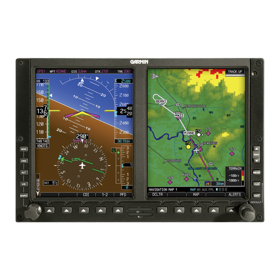
Garmin G500 Manual
Primary flight and multifuction display system
Hide thumbs
Also See for G500:
- Pilot's manual (410 pages) ,
- Instructions manual (334 pages) ,
- Reference manual (104 pages)
Table of Contents
Advertisement
Advertisement
Table of Contents

Related Manuals for Garmin G500


Summary of Contents for Garmin G500
- Page 2 14, 15 Updated section 2.3 with limitation on use of helicopter databases and SD card usage with GSR 56 datalink. Added information on airport directory database. AFMS, GARMIN G500 PFD/MFD SYSTEM 190-01102-01 Rev. 9 FAA APPROVED Page 2 of 40...
- Page 3 Inserted new section 2.3 for moving map limitations. Moved rate-of-turn failure description from section 3.3.1 to section 3.3.2. Added checkbox for disabled altitude alerter in section 4.4. AFMS, GARMIN G500 PFD/MFD SYSTEM 190-01102-01 Rev. 9 FAA APPROVED Page 3 of 40...
- Page 4 Date: 08-18-2011 Added attitude/air data interface to section 4.6. Added GDU 620 as an autopilot attitude source to section 4.6.1. Clarified dual autopilot interface in section 4.6.9. AFMS, GARMIN G500 PFD/MFD SYSTEM 190-01102-01 Rev. 9 FAA APPROVED Page 4 of 40...
- Page 5 Added airspeed bug description in Section 4.1. Removed Altitude Alerter section 4.4. Added electric standby attitude indicator procedure as new section 4.4. Updated autopilot procedures throughout section 4.6. AFMS, GARMIN G500 PFD/MFD SYSTEM 190-01102-01 Rev. 9 FAA APPROVED Page 5 of 40...
- Page 6 Section 1.1. Updated applicable system software in Section 2.2. See Page 1 Corrected Auto Slew description in Section 2.12. Updated Bendix/King Altitude Preselect functionality in Section 4.6.6.3. AFMS, GARMIN G500 PFD/MFD SYSTEM 190-01102-01 Rev. 9 FAA APPROVED Page 6 of 40...
-
Page 7: Table Of Contents
............29 ARNINGS AUTIONS DVISORIES SECTION 4. NORMAL PROCEDURES ............32 PFD K & PFD S ................ 32 MFD K & MFD S ..............32 NOBS AFMS, GARMIN G500 PFD/MFD SYSTEM 190-01102-01 Rev. 9 FAA APPROVED Page 7 of 40... - Page 8 G500 S .......... 34 UTOPILOT PERATIONS WITH THE YSTEM SECTION 5. PERFORMANCE ..............40 SECTION 6. WEIGHT AND BALANCE ............40 SECTION 7. SYSTEM DESCRIPTIONS ............. 40 AFMS, GARMIN G500 PFD/MFD SYSTEM 190-01102-01 Rev. 9 FAA APPROVED Page 8 of 40...
-
Page 9: Section 1. General
PFD is not usable. These standby instruments should be included in the pilot’s normal instrument scan and may be referenced if the PFD data is in question. A second G500 system installed on the co-pilot’s side does not require additional standby instruments. -
Page 10: Navigation Sources
Attitude and Heading Reference System. The AHRS will still operate in a reversionary mode if the GPS fails, and the PFD attitude display will still be presented, see Paragraph 2.8. The G500 HSI can be selected to display course deviation information from up to four independent sources: two GPS, and two VHF NAV. -
Page 11: Autopilot Interface
HSI. For multiple GPS/NAV systems, the G500 acts as a selection hub for the autopilot’s NAV mode, and the G500 may also provide GPS Steering data. -
Page 12: Audio Panel
The HSDB interfaces are installed to so that maximum data path redundancy is achieved. However, depending on the number of HSDB units installed, failure of one HSDB unit may result in loss of data on the G500 from “downstream” HSDB units. Any loss of data will be annunciated on the G500. -
Page 13: Single G500 Operational Block Diagram
1.11 Single G500 Operational Block Diagram Equipment Installed per this STC (optional) Adapter to Aircraft Systems GAD 43/43e Magnetometer Electric GMU 44 Standby Attitude*** PFD/MFD Display AHRS GRS 77 (optional) GDU 620 Air Data Computer GDC 74() Temperature Probe GTP 59 Audio Panel No. -
Page 14: Dual G500 Operational Block Diagram
1.12 Dual G500 Operational Block Diagram AFMS, GARMIN G500 PFD/MFD SYSTEM 190-01102-01 Rev. 9 FAA APPROVED Page 14 of 40... -
Page 15: Definitions
TAWS: Terrain Awareness and Warning System (a TSO-C151b function) TCAS: Traffic Collision and Avoidance System TIS: Traffic Information Service VFR: Visual Flight Rules VMC: Visual Meteorological Conditions V/S: Vertical Speed AFMS, GARMIN G500 PFD/MFD SYSTEM 190-01102-01 Rev. 9 FAA APPROVED Page 15 of 40... -
Page 16: Section 2. Limitations
The G500 utilizes several databases. Database titles display in yellow if expired or in question (Note: the G500 receives the calendar date from the GPS, but only after acquiring a position fix.). Database cycle information is displayed at power up on the MFD screen, but more detailed information is available on the AUX pages. -
Page 17: Ahrs Operational Area
3) North of 70° North latitude between longitude 85° E and 114° E 4) South of 55° South latitude between longitude 120° E and 165° E Loss of the G500 heading and attitude may occur near the poles, but this will not affect the GPS track or standby attitude indicator. -
Page 18: Navigation Angle
Mach number. The G500 airspeed tape displays a red low-speed awareness band at the lower range of the airspeed tape. This low-speed awareness band is configured to a fixed value. -
Page 19: Course Pointer Auto Slewing
2.12 Course Pointer Auto Slewing The G500 HSI will auto slew, i.e. automatically rotate the GPS course pointer to the desired course defined by each GPS leg. The system will also auto slew the VHF NAV course pointer when the CDI transitions to a LOC setting if an ILS, LOC, LOC BC, LDA, or SDF approach is loaded in the GPS/SBAS navigator. -
Page 20: Terrain Proximity Function
TAWS alerts on the PFD of the G500 System are only displayed from the GPS/TAWS navigator interfaced as GPS 1 and are displayed regardless of the system 1-2 setting, which drives all other PFD and MFD data used by the G500. 2.17 Datalinked Weather Display (XM or GFDS weather) Datalink weather data is provided by an optional GDL 69 (XM) or GSR 56 (GFDS) interface. -
Page 21: Active Weather Radar
2.19 Active Weather RADAR RADAR is broadcasting energy while in Weather or Ground mapping modes. If the G500 system is configured to control an airborne weather radar unit, observe all safety precautions, including: Do not operate in the vicinity of refueling operations. -
Page 22: Kinds Of Operations
This may be from either the PFD or the standby instruments. (i.e. all “1a” items or all “1b” items from the table above) ** For IFR flight a fully functional G500 system should not generate system alerts, which indicate faults within the system or any interfaced equipment. -
Page 23: Esi-1000 Electronic Standby Instrument
Video images displayed on the MFD are intended for use as an aid to situational awareness only. Aircraft maneuvering based solely on the MFD video display is prohibited. AFMS, GARMIN G500 PFD/MFD SYSTEM 190-01102-01 Rev. 9 FAA APPROVED Page 23 of 40... -
Page 24: Section 3. Emergency Procedures
PFD. Rate-of-turn information (heading trend vector) will not be available. A heading failure will also occur as described in Section 3.2.1. Use Standby Attitude Indicator. Seek VFR conditions or land as soon as practical. AFMS, GARMIN G500 PFD/MFD SYSTEM 190-01102-01 Rev. 9 FAA APPROVED Page 24 of 40... - Page 25 ALT NO COMP and IAS NO COMP alerts will be present. 3.1.4 Loss of Electrical Power In the event of a total loss of electrical power, the G500 system will cease to operate and the pilot must utilize the standby instruments to fly the aircraft.
- Page 26 STBY PWR button is inadvertently pressed and the red gyro warning flag is displayed, press the STBY PWR button again to return to battery power operation (red gyro warning flag should not be displayed). AFMS, GARMIN G500 PFD/MFD SYSTEM 190-01102-01 Rev. 9 FAA APPROVED Page 26 of 40...
-
Page 27: Abnormal Procedures
TO/FROM indication. Localizer deviations will not be affected by the selected course, and reverse sensing will occur when tracking inbound on a localizer back course. AFMS, GARMIN G500 PFD/MFD SYSTEM 190-01102-01 Rev. 9 FAA APPROVED Page 27 of 40... - Page 28 PFD 2 circuit breaker(s) [if installed] – PULL AHRS 2 circuit breaker(s) [if installed] – PULL ADC 2 circuit breaker(s) [if installed] – PULL GAD circuit breaker(s) [if installed] – PULL AFMS, GARMIN G500 PFD/MFD SYSTEM 190-01102-01 Rev. 9 FAA APPROVED Page 28 of 40...
-
Page 29: Warnings, Cautions, And Advisories
Warnings, Cautions, and Advisories The following tables show the color and significance of the warning, caution, and advisory messages which may appear on the G500 displays. NOTE The G500 Cockpit Reference Guide and the G500 Pilot’s Guide contain detailed descriptions of the annunciator system and all warnings, cautions and advisories. - Page 30 / or provide the pilot with any traffic awareness. NO AP DATA Verify autopilot Autopilot mode of operation is mode of operation not available. using alternate means. AFMS, GARMIN G500 PFD/MFD SYSTEM 190-01102-01 Rev. 9 FAA APPROVED Page 30 of 40...
- Page 31 View and understand all advisory messages. Messages may appear Typically, they indicate communication issues under the MFD - within the G500 System. Refer to the G500 Cockpit ALERTS soft key. Reference for appropriate pilot or service action. AFMS, GARMIN G500 PFD/MFD SYSTEM 190-01102-01 Rev.
-
Page 32: Section 4. Normal Procedures
Assigning the function of the knob is done by pressing/releasing one of the dedicated function buttons to the left of the display. The knob defaults back to HDG if it is not rotated for a period of 10 seconds. The Garmin G500 PFD/MFD System Cockpit Reference describes each function and its operation. -
Page 33: Altitude Synchronization
PFD will adjust both PFDs, but the standby must still be set by the pilot. Reference the Garmin G500 Cockpit Reference Guide for a complete description and the usage of synchronization in dual installations. -
Page 34: Autopilot Operations With The G500 System
The G500 PFD/MFD System offers various integration capabilities dependent mainly upon the type of autopilot installed in a particular aircraft. The G500 installation in this aircraft provides the following autopilot integration capabilities: This installation does not interface with the autopilot (basic wing leveling autopilot or no autopilot is installed in the aircraft). - Page 35 When operating the autopilot in NAV mode, the deviation information from the installed navigation sources (i.e. GPS1, GPS2, NAV1, NAV2) is switched via the G500 PFD display. Whatever is displayed on the HSI is the NAV source the autopilot is following. Most autopilots also use the course datum to determine the best intercept angles when operating in NAV mode.
- Page 36 G500 to the autopilot. The G500 receives this data from the GPS. In dual GPS installations, the G500 sends Roll Steering information for the GPS which is currently selected for use via the PFD 1-2 button.
- Page 37 Changing the selected altitude bug while ALTC mode is engaged will result in cancellation of ALTC mode. Verify the autopilot mode after changing the selected altitude. AFMS, GARMIN G500 PFD/MFD SYSTEM 190-01102-01 Rev. 9 FAA APPROVED Page 37 of 40...
- Page 38 Press and hold the vertical trim rocker switch on the autopilot in the desired direction, or Press the CWS button on the control wheel to synchronize the vertical speed bug to the current vertical speed. AFMS, GARMIN G500 PFD/MFD SYSTEM 190-01102-01 Rev. 9 FAA APPROVED Page 38 of 40...
- Page 39 G500, the command bars will be displayed at the maximum distance allowed by the G500. As the aircraft pitch changes to satisfy the command bars, the bars will continue to be displayed at the maximum distance from the aircraft attitude icon until the aircraft pitch deviation is within the command display limit.
-
Page 40: Section 5. Performance
4.6.9 GAD 43 Operation The GAD 43 Adapter provides attitude, heading, and barometric correction information from the G500 System to the autopilot. The GAD 43 can also be configured to provide synchro heading output to other systems and its attitude output can be used for RADAR stabilization.
Need help?
Do you have a question about the G500 and is the answer not in the manual?
Questions and answers