Table of Contents
Advertisement
GE Digital Energy
Power Quality
Operating Manual
Uninterruptible Power supply
Digital Energy™
SG Series
400 & 500 kVA
480 Vac UL / Series 1
Manufactured by:
GE Consumer & Industrial SA
General Electric Company
CH – 6595 Riazzino (Locarno)
Switzerland
T +41 (0)91 / 850 51 51
F +41 (0)91 / 850 51 44
www.gedigitalenergy.com
GE imagination at work
Advertisement
Table of Contents

Subscribe to Our Youtube Channel
Related Manuals for GE Digital Energy SG 400 kVA


Summary of Contents for GE Digital Energy SG 400 kVA
- Page 1 Digital Energy™ SG Series 400 & 500 kVA 480 Vac UL / Series 1 Manufactured by: GE Consumer & Industrial SA General Electric Company CH – 6595 Riazzino (Locarno) Switzerland T +41 (0)91 / 850 51 51 F +41 (0)91 / 850 51 44 www.gedigitalenergy.com...
- Page 2 The present publication and any other documentation supplied with the UPS system is not to be reproduced, either in part or in its entirety, without the prior written consent of GE. The illustrations and plans describing the equipment are intended as general reference only and are not necessarily complete in every detail.
- Page 3 Thank you for choosing GE ! START UP AND COMMISSIONING A GE Global Services Field Engineer must perform start-up and commissioning of the UPS. Please Contact GE. Global Services at least two weeks prior to schedule start-up and commissioning at 1-800-637-1738, or by E-mail at pqservices@ge.com...
-
Page 4: Safety Instructions
UPS. While every care has been taken to ensure the completeness and accuracy of this manual, GE assumes no responsibility or liability for any losses or damages resulting from the use of the information contained in this document. -
Page 5: Table Of Contents
Table of contents Page IMPORTANT SAFETY INSTRUCTIONS ......................7 INTRODUCTION ............................10 DESCRIPTION ..............................11 BLOCK DIAGRAM AND MAIN ELEMENTS ......................11 OPERATION MODES................................ 12 3.2.1 Normal operation mode ..........................12 3.2.2 Utility failure operation ..........................12 3.2.3 Utility recovery operation........................... 13 3.2.4 Automatic Bypass............................ - Page 6 PROCEDURES FOR UPS FUNCTIONING AS FREQUENCY CONVERTER ............ 48 7.2.1 Start-up of the SG Series as frequency converter ................48 7.2.2 Complete UPS shutdown (No Load supply)..................49 7.2.3 Restore to normal operation after “total off” ..................50 7.2.4 Restore to normal operation after EPO (Emergency Power Off) ..........51 PROCEDURES FOR PARALLEL SYSTEM ........................
-
Page 7: Important Safety Instructions
IMPORTANT SAFETY INSTRUCTIONS SAVE THESE INSTRUCTIONS This manual contains important instructions for models SG Series 400 & 500 kVA that should be followed during installation and maintenance of the UPS and battery. GENERAL Move the UPS in an upright position in its original package to the final destination room. To lift the cabinets, use a forklift or lifting belts with spreader bars. - Page 8 Safety instructions when working with battery EXTERNAL BATTERY MUST BE INSTALLED AND CONNECTED TO THE UPS BY QUALIFIED SERVICE PERSONNEL. INSTALLATION PERSONNEL MUST READ THIS ENTIRE SECTION BEFORE HANDLING THE UPS AND BATTERY. DANGER! Full voltage and current are always present at the battery terminals. The battery used in this system can provide dangerous voltages, extremely high currents and a risk of electric shock.
-
Page 9: Safety Symbols And Warnings
Safety symbols and warnings Safety warnings The text of this manual contains some warnings to avoid risk to the persons and to avoid damages to the UPS system and the supplied critical loads. The non-observance of the warnings reminding hazardous situations could result in human injury and equipment damages. -
Page 10: Introduction
Power Factor Corrected (PFC) equipment. • No single point of failure Redundant Parallel Architecture (RPA) is an exclusive GE technology. With RPA, SG Series UPS are controlled in a true peer-to-peer configuration where all critical elements and functions (including Bypass) are redundant. -
Page 11: Description
DESCRIPTION BLOCK DIAGRAM AND MAIN ELEMENTS Fig. 3.1-1 Block diagram The SG Series system can be divided into the following main elements: Control System SG Series is designed with microprocessor-controlled signal processing circuits. The interface between the operator and the unit is provided by the monitoring system on the front panel. -
Page 12: Operation Modes
OPERATION MODES 3.2.1 Normal operation mode During normal operation, the Rectifier converts input AC power to DC. The DC power provides input power for the Inverter and charging power for the Battery. The Inverter converts the DC power to continuous and regulated AC power, which supplies the critical load. -
Page 13: Utility Recovery Operation
3.2.3 Utility recovery operation As soon as the AC input power recovers, the Rectifier will start automatically, supplying DC power to the Inverter and recharging the Battery. If the Inverter was previously shut down due to low Battery, the Load will be initially powered by Utility through the Automatic Bypass. -
Page 14: Parallel System Operation
PARALLEL SYSTEM OPERATION 3.3.1 Introduction to the parallel system Two or more equal power units can be paralleled to increase the output power (paralleling for capacity) or to improve the overall reliability of an UPS system (paralleling for redundancy). The outputs of parallel units are connected to a common power bus, and in normal operation the units connected on the parallel bus share the Load equally. -
Page 15: Features Of Rpa Parallel System
3.3.2 Features of RPA parallel system The SG Series parallel system is designed to provide a complete Redundant Parallel Architecture, and is free from common equipment. Not only the Inverters are redundant, but also the Bypass functions are designed with redundant modular concept. -
Page 16: Rectifiers Paralleled On The Same Battery
(accessible only through password), and can therefore only be done by a qualified engineer from GE. Usually each Rectifier-Inverter Unit runs with its own Battery. In case of parallel units are running with a Common Battery (max. 4 UPS - see Fig 3.4-1), the sharing circuit between individual Rectifier is integrated in the communication bus of the system in order to assure an equal sharing of the Rectifiers output currents. -
Page 17: Recycling At The End Of Service Life
It does not contain CFCs (Carbon Fluor Clorid) or HCFCs (Halogen Carbon Fluor Clorid). GE, in compliance with environment protection recommends to the User that the UPS equipment, at the end of its service life, must be recovered conforming to the local applicable regulations. -
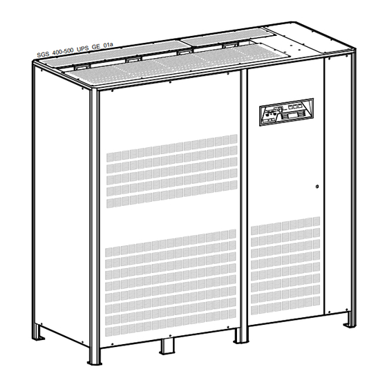
Page 18: Layout
LAYOUT LAYOUT SG Series 400 & 500 kVA Fig. 4.1-2 SG Series general view with open door Fig. 4.1-1 SG Series general view Fig. 4.1-4 Control Panel Fig. 4.1-3 Manual operated switches SNMP Customer Interface Board UPS output switch Manual Bypass switch SNMP Advanced SNMP Card (option) Fig. -
Page 19: Control Panel
CONTROL PANEL CONTROL PANEL Fig. 5.1-1 Control Panel TABLE OF FUNCTIONS AND INDICATIONS ON CONTROL PANEL Key to switch the Inverter ON ( I ) inverter on/off (This key is also used to reset “total off” if pressed simultaneously with total off push button). - Page 20 General alarm condition It blinks when one or more alarm is activated. The internal buzzer is ON. The LED remains lighted (with alarm condition still present) and the buzzer stops as the key “mute” has been pressed. alarm LED ON indicates that a regular maintenance service is needed. May be reset by a service technician only.
-
Page 21: Lcd Screen
LCD SCREEN The user interface consists of a back lit LCD screen having: • 4 lines with 20 characters (standard version for Latin characters). • 6 keys (the function is described for each operating mode). The operation is extremely simple and is structured on three important main menus related to the UPS operation, as follows: metering A UPS must offer some metering information for the user to be able to examine the... -
Page 22: Metering Mode
METERING MODE The metering mode is entered any time the metering button is pressed. While in this mode the LCD will display a series of screens containing metering information. In this mode the buttons perform the following functions: metering Scrolls forward to the next screen. alarms Abandons the metering mode and enters the alarms mode. - Page 23 Rectifier Utility data screen This screen refers to the AC source supplying the Rectifier. This screen displays: • Iout1 = output current Rectifier Bridge. • Iout2 = output current 2 Rectifier Bridge (optional 12 pulse Rectifiers only). • The voltage levels between the three phases (line-to-line). •...
- Page 24 Load on phases screen 2 This screen displays for each phase: • The Load active power (kW) (for RPA: total value of Parallel System). • The Load apparent power (kVA) (for RPA: total value of Parallel System). metering LOAD ON PHASES L1= 111.9kW 139.8kVA alarms...
-
Page 25: Alarms
– Scrolls backward to the previous screen. Display the main screen for this mode. The events displayed are the standard GE events as described in the Section 6.7 - EVENTS (Alarms and Messages). The information displayed includes: • The exact date and time when the event occurred. -
Page 26: Parameters
PARAMETERS The parameters mode is entered any time the parameters button is pressed. The LCD will display a series of screens containing the user parameters, accessible without password protection. The buttons perform the following functions: metering Abandon parameters mode and enter metering mode. alarms Abandon parameters mode and enter alarms mode. - Page 27 3 – Scroll to the next screen (+). The third screen is displayed. metering Tel1:002186394567 Tel1 enabled: alarms – Tel2:004017464340 Tel2 enabled: parameters 4 – Move the selection (underscore cursor) to the next parameter in this page (-). metering Tel1:002186394567 Tel1 enabled: alarms –...
-
Page 28: Edit Mode
EDIT MODE The EDIT MODE is entered from the parameters mode when the ok button is pressed. During this mode the LCD will display a special editing screen for the parameter being edited. The screen contents during Edit mode is: •... - Page 29 3 – Change the selected character (-). metering EDIT MODE PHONE NUMBER 2 alarms – 005017464340 + SCROLL - CHANGE parameters 4 – Change the selected character (-). metering EDIT MODE PHONE NUMBER 2 alarms – 006017464340 + SCROLL - CHANGE parameters 5 –...
- Page 30 3 – Change to 4800. metering EDIT MODE PRINTER BAUDRATE alarms – 4800 + SCROLL - CHANGE parameters 4 – Press ok: the screen will return to parameters mode saving the new value. metering PRINTER SETUP Baud=4800 Parity=O alarms – Bits=8 Handshake=XON Print All = N parameters...
-
Page 31: User Parameters
USER PARAMETERS Pressing the Parameters button displays a series of screens containing the user parameters on the LCD panel. This first parameter level in not protected by password, therefore the user can freely adapt these parameters to their needs. The meaning of the user parameters and their use is described below (buttons performance is described to Section 7.3). - Page 32 Telephone numbers Tel1 : m e te rin g Tel1 en ab led : N a la rm s – Tel2 : Tel2 en ab led : N p a ra m e te rs Tel1 This parameter specifies a first telephone number to be used for modem dial-out. The telephone number has a maximum 39 characters and cannot contain blanks.
- Page 33 Printer Set-up The UPS is capable of communicating to a serial printer, to printout disparate information. Please be sure to have a serial printer, that is a printer with a serial RS232 interface. This is the only printer-interface supported by the UPS. m etering PRINTER SETUP Baud=2400 Parity=O...
-
Page 34: Events (Alarms And Messages)
EVENTS (ALARMS AND MESSAGES) Each of the following listed events can be displayed on the LCD screen or on PC where the “PowerJump Manager” or “PowerJump DataShield” is installed. Alarms and Messages are differently specified because the alarms are indicating an abnormal functioning of the UPS (which are additionally signalled with the LED alarm and acoustically with the buzzer), while the messages indicate the various states of operation of the UPS (stored in the events list, but not activating the LED alarm and the buzzer). - Page 35 Code Alarms Meaning The Battery has been discharged and reached “stop operation” LOW BATTERY time-out (default 3 minutes), and the Inverter will be shut down. 4115 VOLTAGE It will restart automatically only when the Battery has recharged enough for a minimum runtime. Dangerous high DC Voltage caused Inverter shutdown.
- Page 36 Code Alarms Meaning K6 OPENING K6 closed despite an opening command being issued. 4405 FAILURE Signalled by auxiliary contact. A faulty current has been detected in the static-switch causing the opening of the contactor K6 for 10 seconds. 4406 FAILURE After 3 times K6 remains definitively open.
- Page 37 Code Alarms Meaning An over-temperature condition has been detected on Inverter. 4955 OVERTEMPERATURE Elapsed “stop operation” time, Inverter shutdown. With Utility OK, Load is transferred on Utility. LOAD OFF DUE TO Load Off after time-out of “stop operation” for overload on 4998 EXTENT.
-
Page 38: Messages List
6.6.2 Messages list Code Message Meaning The microprocessor has detected an incorrect operation: WATCHDOG 4002 Transfers the Load on Utility and performs a program reset. RESET The Inverter will restart automatically and will supply the Load. RECTIFIER Rectifier Input Utility is again within the admitted tolerance 4111 UTILITY OK (voltage, frequency and phase). - Page 39 Code Message Meaning TOTAL Push-button “total off” on the UPS Control Panel has been 4561 pressed, with the output circuit switch Q1 closed. DETOUR The auxiliary contact indicates that Manual Bypass Q2 was 4562 closed. DETOUR The auxiliary contact indicates that Manual Bypass Q2 was 4564 opened.
-
Page 40: Event Report Sg Series
6.6.3 Event report SG Series In case of failure or malfunctioning, before calling the nearest Service Center, please note the most important data of your UPS and the most recent events. In order to make the diagnosis easier from our Diagnostic Centre we suggest you make a copy of this page, fill it out with the requested data and send it by fax. -
Page 41: Operation
If you encounter any problems during the following procedures, you should not continue, but contact GE Global Services. Find on the following pages the descriptions of the various procedures of start-up and shutdown for single and parallel UPS’s, divided into the following principal chapters:... -
Page 42: Procedures For Single Ups
PROCEDURES FOR SINGLE UPS 7.1.1 Start-up of the SG Series Verify with open front door: Switch Q1 and Q2 must be open (Pos. O). 1. Connect the Utility power on the UPS. (In case of separate inputs for Rectifier and Bypass, connect both). -
Page 43: Maintenance Shutdown (Load On Q2)
7.1.2 Maintenance shutdown (Load on Q2) Initial status: Load supplied from Inverter. 1. Press “inverter off” ( O ) key and hold until the LED inside the Inverter symbol turns OFF. • Load is transferred to Utility. • Inverter shuts down. •... -
Page 44: From Manual Bypass (Q2) To Normal Function Vfi
7.1.3 From Manual Bypass (Q2) to normal function VFI Initial status: Load supplied from Manual Bypass. 1. Close Q1 (Pos. I). • Bypass connects to Load. LED Load on Bypass lights up. • Rectifier starts automatically and LED in Rectifier symbol and LED Battery charge light up. -
Page 45: Complete Ups Shutdown (No Load Supply)
7.1.4 Complete UPS shutdown (No Load supply) NOTE ! The Load must be disconnected. Initial status: Load supplied from Inverter. 1. Press “total off” button. • Load is disconnected from UPS. • Rectifier is shut down and all output and input contactors will be opened. -
Page 46: Restore To Normal Operation After "Total Off
7.1.5 Restore to normal operation after “total off” View of the panel after pressing the button “total off”. • All Contacts are open; • Rectifier, Inverter and Static-Switch shutdown. • Press mute, to reset alarm and buzzer. The Battery remains connected to the UPS in case of configuration without external Battery Breaker Release! 1. -
Page 47: Restore To Normal Operation After Epo (Emergency Power Off)
7.1.6 Restore to normal operation after EPO (Emergency Power Off) UPS panel after activation of EPO (Emergency Power Off) with Utility not available, i.e. complete shutdown of the UPS. In this case wait until Utility is again available, then proceed to restart the UPS as described below. -
Page 48: Procedures For Ups Functioning As Frequency Converter
PROCEDURES FOR UPS FUNCTIONING AS FREQUENCY CONVERTER When the functions as a Frequency Converter, the Automatic Bypass and SG Series Manual functions are disabled. Bypass Therefore the Load cannot be transferred to Utility in case of overload, short circuit, or Inverter failure. -
Page 49: Complete Ups Shutdown (No Load Supply)
7.2.2 Complete UPS shutdown (No Load supply) NOTE ! The Load must be disconnected. Initial status: Load supplied from Inverter. 1. Press “total off” button. • Load is disconnected from UPS. • Rectifier is shut down and all output and input contactors will be opened. -
Page 50: Restore To Normal Operation After "Total Off
7.2.3 Restore to normal operation after “total off” View of the panel after pressing the button “total off”. • All Contacts are open; • Rectifier, Inverter and Static-Switch shutdown. • Press mute, to reset alarm and buzzer. The Battery remains connected to the UPS in case of configuration without external Battery Breaker Release! 1. -
Page 51: Restore To Normal Operation After Epo (Emergency Power Off)
7.2.4 Restore to normal operation after EPO (Emergency Power Off) UPS panel after activation of EPO (Emergency Power Off) with Utility not available, i.e. complete shutdown of the UPS. In this case wait until Utility is again available, then proceed to restart the UPS as described below. -
Page 52: Procedures For Parallel System
7.3 PROCEDURES FOR PARALLEL SYSTEM 7.3.1 Parallel System start-up Verify on all Units, with open front door: Switches Q1 and Q2 must be open (Pos. O). 1. Connect the Utility power on all UPS’s. (In case of separate inputs for Rectifier and Bypass, connect both). •... - Page 53 4. Press “inverter on” ( I ) key on first unit. • Soft-start of Inverter, indicated with blinking LED. • At the end of Soft-start the LED Inverter remains lit. • In case of sufficient output power, the output will transfer to Inverter. •...
-
Page 54: Maintenance System Shutdown (Load Supplied From Q2 On All Units)
7.3.2 Maintenance system shutdown (Load supplied from Q2 on all Units) Initial status: Load supplied from all Inverters. First operated unit All other units of the system ( O ) 1. Press “inverter off” key on all Units, and hold until the LED inside the Inverter symbol turns OFF. - Page 55 3. Open Q1 (Pos. O) and then press “total off” button on all Units. The Bypass of all Units will disconnect and all Rectifiers are shutdown. • Press mute, to reset alarm and buzzer. The Battery remains connected to the UPS in case of configuration without external Battery Breaker Release! First operated unit All other units of the system...
-
Page 56: From Manual Bypass (Q2) To Normal Function Vfi
7.3.3 From Manual Bypass (Q2) to normal function VFI Initial status: Load supplied from Manual Bypass. All Q2 of the system are closed. First operated unit All other units of the system 1. Close Q1 (Pos. I) on all Units. The Rectifiers will start automatically and at the closure of Q1 of the last Unit, the Bypass of all Units will be activated. - Page 57 4. Press “inverter on” ( I ) key on first unit. • Soft-start of Inverter, indicated with blinking LED. • At the end of Soft-start the LED Inverter remains lit. • In case of sufficient output power, the output will transfer to Inverter. •...
-
Page 58: Separate A Unit From The Parallel System (System Redundancy)
7.3.4 Separate a Unit from the parallel system (System Redundancy) Initial status: Load supplied from all Inverters. First operated unit All other units of the system 1. Press and hold “inverter off” ( O ) key on the Unit to separate, until the LED turns OFF. Load supplied from Inverter(s) of the other Unit(s) of the parallel system First operated unit All other units of the system... - Page 59 3. Disconnect the Battery from the Unit to separate (only for UPS configuration without external Battery Breaker Release). • Wait 5 minutes for DC-Link Capacitors to discharge. Before you proceed with any kind of metering Ub=15V Ib= + 0A Battery Temp= + 20 °...
-
Page 60: Reconnect A Unit To A Parallel System
7.3.5 Reconnect a Unit to a parallel system 1. Connect the Utility supply on the separated Unit. • Press mute, to reset alarm and buzzer. First operated unit All other units of the system 2. Close Q1 (Pos. I) on the separated Unit. Rectifier starts automatically. -
Page 61: Parallel System Shutdown (No Load Supply)
7.3.6 Parallel system shutdown (No Load supply) NOTE ! The Load must be disconnected. Initial status: Load supplied from all Inverters. First operated unit All other units of the system 1. Press “total off” button on any one of the units. •... - Page 62 3. Disconnect the Battery from all Units (only for UPS configuration without external Battery Breaker Release). • Wait 5 minutes for DC-Link Capacitors to discharge Before you proceed with any kind of metering Ub=15V Ib= + 0A Battery Temp= + 20 ° C intervention on the UPS, make sure the DC-Link alarms –...
-
Page 63: Restore To Normal Operation After "Total Off
7.3.7 Restore to normal operation after “total off” View of the panel after pressing the button “total off”. • All Contacts are open; • Rectifier, Inverter and Static-Switch shutdown. • Press mute, to reset alarm and buzzer. The Battery remains connected to the UPS in case of configuration without external Battery Breaker Release! First operated unit All other units of the system... - Page 64 Proceed with step 2 only when the LED 3 remains constantly lit on all units of the parallel system 2. Connect the battery to all Units by LED 3 closing the external Battery Breaker Release. 3 Press “inverter on” ( I ) key on first unit. •...
-
Page 65: Restore To Normal Operation After Epo (Emergency Power Off)
7.3.8 Restore to normal operation after EPO (Emergency Power Off) panel after activation (Emergency Power Off) with Utility not available, i.e. complete shutdown of the UPS and LCD screen OFF. In this case wait until Utility is again available, then proceed to restart the UPS as described below Points 1 through 3. - Page 66 Proceed with step 2 only when the LED 3 remains constantly lit on all units of the parallel system 3. Connect the battery to all Units by LED 3 closing the external Battery Breaker Release. 4. Press “inverter on” ( I ) key on first Unit. •...
-
Page 67: Procedures For Parallel System With Common Battery
7.4 PROCEDURES FOR PARALLEL SYSTEM WITH COMMON BATTERY 7.4.1 Parallel System start-up Verify on all Units, with open front door: Switches Q1 and Q2 must be open (Pos. O). 1. Connect the Utility power on all UPS’s. (In case of separate inputs for Rectifier and Bypass, connect both). •... - Page 68 4. Press “inverter on” ( I ) key on first unit. • Soft-start of Inverter, indicated with blinking LED. • At the end of Soft-start the LED Inverter remains lit. • In case of sufficient output power, the output will transfer to Inverter. •...
-
Page 69: Maintenance System Shutdown (Load Supplied From Q2 On All Units)
7.4.2 Maintenance system shutdown (Load supplied from Q2 on all Units) Initial status: Load supplied from all Inverters. First operated unit All other units of the system 1. Press “inverter off” ( O ) key on all Units, and hold until the LED inside the Inverter symbol turns OFF. - Page 70 3. Open Q1 (Pos. O) and then press “total off” button on all Units. The Bypass of all Units will disconnect and all Rectifiers are shutdown. • Press mute, to reset alarm and buzzer. The Battery remains connected to the UPS in case of configuration without external Battery Breaker Release! First operated unit All other units of the system...
-
Page 71: From Manual Bypass (Q2) To Normal Function Vfi
7.4.3 From Manual Bypass (Q2) to normal function VFI Initial status: Load supplied from Manual Bypass. All Q2 of the system closed. First operated unit All other units of the system 1. Close Q1 (Pos. I) on all Units. The Rectifiers will start automatically and at the closure of Q1 of the last Unit, the Bypass of all Units will be activated. - Page 72 4. Press “inverter on” ( I ) key on first unit. • Soft-start of Inverter, indicated with blinking LED. • At the end of Soft-start the LED Inverter remains lit. • In case of sufficient output power, the output will transfer to Inverter. •...
-
Page 73: Separate A Unit From The Parallel System (System Redundancy)
7.4.4 Separate a Unit from the parallel system (System Redundancy) Initial status: Load supplied from all Inverters. First operated unit All other units of the system 1. Press and hold “inverter off” ( O ) key on the Unit to separate, until the LED turns OFF. Load supplied from Inverter(s) of the other Unit(s) of the parallel system First operated unit All other units of the system... - Page 74 3. Disconnect the Battery from the Unit to separate (only for UPS configuration without external Battery Breaker Release). • Wait 5 minutes for DC-Link Capacitors to discharge. Before you proceed with any kind of metering Ub=15V Ib= + 0A Battery Temp= + 20 °...
-
Page 75: Reconnect A Unit To A Parallel System
7.4.5 Reconnect a Unit to a parallel system 1. Connect the Utility supply on the separated Unit. • Press mute, to reset alarm and buzzer. First operated unit All other units of the system 2. Close Q1 (Pos. I) on the separated Unit. Rectifier starts automatically. -
Page 76: Parallel System Shutdown (No Load Supply)
7.4.6 Parallel system shutdown (No Load supply) NOTE ! The Load must be disconnected. Initial status: Load supplied from all Inverters. First operated unit All other units of the system 1. Press “total off” button on any one of the units. •... - Page 77 3. Disconnect the Battery from all Units (only for UPS configuration without external Battery Breaker Release). • Wait 5 minutes for DC-Link Capacitors to discharge Before you proceed with any kind of metering Ub=15V Ib= + 0A Battery Temp= + 20 ° C intervention on the UPS, make sure the DC-Link alarms –...
-
Page 78: Restore To Normal Operation After "Total Off
7.4.7 Restore to normal operation after “total off” View of the panel after pressing the button “total off”. • All Contacts are open; • Rectifier, Inverter and Static-Switch shutdown. • Press mute, to reset alarm and buzzer. The Battery remains connected to the UPS in case of configuration without external Battery Breaker Release! First operated unit All other units of the system... - Page 79 Proceed with step 2 only when the LED 3 remains constantly lit on all units of the parallel system 2. Connect the battery to all Units by LED 3 closing the external Battery Breaker Release. 3 Press “inverter on” ( I ) key on first unit. •...
-
Page 80: Restore To Normal Operation After Epo (Emergency Power Off)
7.4.8 Restore to normal operation after EPO (Emergency Power Off) panel after activation (Emergency Power Off) with Utility not available, i.e. complete shutdown of the UPS and LCD screen OFF. In this case wait until Utility is again available, then proceed to restart the UPS as described below Points 1 through 3. - Page 81 Proceed with step 2 only when the LED 3 remains constantly lit on all units of the parallel system 3. Connect the battery to all Units by LED 3 closing the external Battery Breaker Release. 4. Press “inverter on” ( I ) key on first Unit. •...
-
Page 82: Options
The Advanced SNMP Card is an interface to the Ethernet Network, and provides UPS information via the standard SNMP Protocol (UPS-MIB (RFC-1628); GE Single MIB; GE Parallel MIB). The UPS can therefore be managed by a Network Management System (NMS) or by our applications (for instance JUMP), which... -
Page 83: Connection For Options
AUX. BUZZER yellow/brown Alarm STOP OPERATION Mute Test GE Digital Energy P.S.: The above mentioned colors are suitables only for XY standard cable 8 1/2" in 216mm Fig. 8.3.1-1 Remote Signalling Box connection Terminals X3, X4 and X15 fitted inside the Remote Signalling Box. -
Page 84: Maintenance
A regular maintenance check of your installation guarantees higher reliability of your safe critical power supply. Preventive maintenance work on the UPS can be done only by trained Service technicians. We therefore recommend you sign a Maintenance and Service contract with GE Global Services @ 1- 800-637-1738 9.1.1 Service check If this lamp lights up during the normal operation, that means that the unit has not been serviced for the last 20,000 hours by a GE trained technician. -
Page 85: Long Shut-Down Periods Of The Ups-System
9.1.5 Long shut-down periods of the UPS-system To guarantee that the Battery is fully charged, the UPS system should be in operation for at least 12 hours every 3 months. If not the Battery may be permanently damaged. 9.1.6 UPS room conditions and temperature The UPS room and the Battery Room have to be maintained clean and free from dust. -
Page 86: Notes
10 NOTES 10.1 NOTES FORM It is recommended to note in this section Notes, with date and short description all the operations performed on the UPS, as: maintenance, components replacement, abnormal situations, etc. Date Description Done by Modifications reserved Page 86/86 OPM_SGS_USM_M40_M50_1US_V020.doc Operating Manual SG Series 400 &...
Need help?
Do you have a question about the Digital Energy SG 400 kVA and is the answer not in the manual?
Questions and answers