Table of Contents
Advertisement
Quick Links
GE Digital Energy
Power Quality
Installation Guide
Uninterruptible Power supply
SG Series 225 & 300
225 & 300 kVA / 480Vac UL / S2
GE Consumer & Industrial SA
General Electric Company
CH – 6595 Riazzino (Locarno)
Switzerland
T +41 (0)91 / 850 51 51
F +41 (0)91 / 850 52 52
www.gepowerquality.com
imagination at work
Advertisement
Table of Contents

Related Manuals for GE SG300


Summary of Contents for GE SG300
- Page 1 Installation Guide Uninterruptible Power supply SG Series 225 & 300 225 & 300 kVA / 480Vac UL / S2 GE Consumer & Industrial SA General Electric Company CH – 6595 Riazzino (Locarno) Switzerland T +41 (0)91 / 850 51 51 F +41 (0)91 / 850 52 52 www.gepowerquality.com...
- Page 2 The present publication and any other documentation supplied with the UPS system is not to be reproduced, either in part or in its entirety, without the prior written consent of GE. The illustrations and plans describing the equipment are intended as general reference only and are not necessarily complete in every detail.
- Page 3 START UP AND COMMISSIONING A GE GLOBAL SERVICES FIELD ENGINEER must perform start-up and commissioning of the UPS. Please Contact GE. GLOBAL SERVICES at least two weeks prior to schedule start-up and commissioning at 1-800-637-1738, or by E-mail at pqservice@ge.com...
- Page 4 While every care has been taken to ensure the completeness and accuracy of this manual, GE assumes no responsibility or liability for any losses or damages resulting from the use of the information contained in this document.
-
Page 5: Table Of Contents
Table of contents Page IMPORTANT SAFETY INSTRUCTIONS ......................6 LAYOUT................................9 LAYOUT SG Series 225 & 300 ...............................9 INSTALLATION............................10 TRANSPORT....................................... 10 3.1.1 Dimensions and weight................................. 10 DELIVERY ......................................11 STORAGE ......................................11 3.3.1 Storage of the UPS ..................................11 3.3.2 Storage of battery ................................... -
Page 6: Important Safety Instructions
IMPORTANT SAFETY INSTRUCTIONS SAVE THESE INSTRUCTIONS This manual contains important instructions for models SG Series 225 & 300 that should be followed during installation and maintenance of the UPS and battery. GENERAL Move the UPS in an upright position in its original package to the final destination room. To lift the cabinets, use a forklift or lifting belts with spreader bars. - Page 7 Safety instructions when working with battery EXTERNAL BATTERY MUST BE INSTALLED AND CONNECTED TO THE UPS BY QUALIFIED SERVICE PERSONNEL ONLY. INSTALLATION PERSONNEL MUST READ THIS ENTIRE SECTION BEFORE HANDLING THE UPS AND BATTERY. DANGER! Full voltage and current are always present at the battery terminals. The battery used in this system can provide dangerous voltages, extremely high currents and a risk of electric shock.
- Page 8 Safety symbols and warnings Safety warnings The text of this manual contains some warnings to avoid risk to the persons and to avoid damages to the UPS system and the supplied critical loads. The non-observance of the warnings reminding hazardous situations could result in human injury and equipment damages.
-
Page 9: Layout
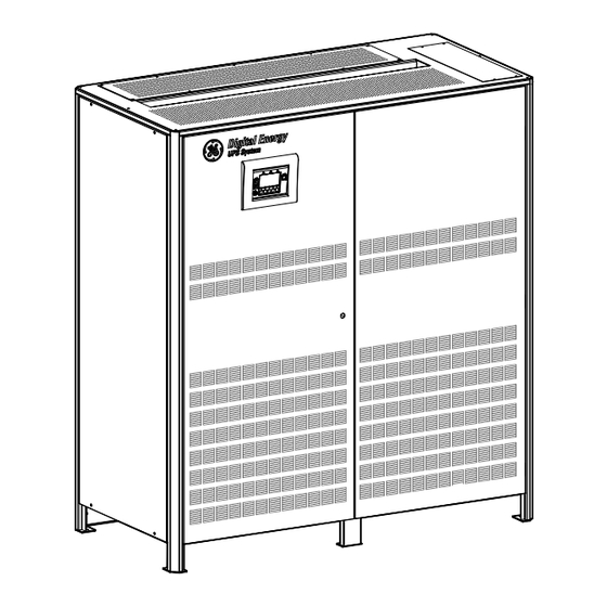
LAYOUT LAYOUT SG Series 225 & 300 Fig. 2.1-1 SG Series 225 & 300 general view Fig. 2.1-2 SG Series 225 & 300 general view with open doors Opening for top cable entry Opening for bottom cable entry Compression lugs for Utility input and Load output Compression lugs... -
Page 10: Installation
INSTALLATION TRANSPORT Forklift Transport UPS only in upright position! The UPS is packaged on a pallet suitable for handling with a forklift. Pay attention to the center of gravity. The UPS must be moved in upright position. Do not tilt cabinets more than +/- 10° during handling. Move the UPS in it’s original package to the final Crane destination site. -
Page 11: Delivery
DELIVERY When delivered, inspect the package integrity and the physical conditions of the cabinets carefully. In case of any damage sustained during transport, immediately inform the carrier and contact your local Service Center. A detailed report of the damage is necessary for any insurance claim. NOTE ! A DAMAGED UPS MUST NEVER BE INSTALLED OR CONNECTED TO UTILITY OR BATTERY! -
Page 12: Place Of Installation
PLACE OF INSTALLATION 3.4.1 UPS location WARNING ! A QUALIFIED ELECTRICAL CONTRACTOR must carry out the installation and cabling of the UPS. If optional cabinets and accessories are included with the UPS, please refer to those accompanying manuals for installation and operating instructions. It is important to have a clean, dust-free environment provided with proper ventilation and air- conditioning to keep the ambient temperature within the specified operating range. - Page 13 Openings for input and output cable connections Battery Utility input Output Load SG Series 225 & 300 openings are provided on the top and the bottom of the UPS for the connection of input Fig. 3.4.1-2 Opening on top of the cabinet for input and output cables and output cables.
-
Page 14: Battery Location
3 - 4 - 5 - 6 UPS 2 UPS 1 Fig. 3.4.1-5 RPA system disposition In case of parallel system, try to place the UPS modules in sequence of their numbers (marked on the packing). If the units are positioned “side by side”, the side panels must be mounted on all units. 3.4.2 Battery location Batteries require a well-ventilated room with controlled temperature to obtain reliable operation. -
Page 15: Ventilation And Cooling
VENTILATION AND COOLING Fig. 3.5-1 Installation on plain floor Fig. 3.5-2 Installation on raised floor The heat produced by the UPS is transferred to the environment by its ventilation. Air inlets for UPS ventilation are located on the front of the UPS, while air outlets are on top of the cabinet. -
Page 16: Unpacking
For parallel systems, the delivery also includes the bus control cables for inter- connecting the UPS modules. Packing material recycling GE, in compliance with environment protection, use only environmentally friendly material. UPS packing materials must be recycled in compliance with all applicable regulations. -
Page 17: Electrical Wiring
ELECTRICAL WIRING WARNING ! UPS installation and connection must be performed by QUALIFIED SERVICE PERSONNEL ONLY. It is the responsibility of the installation technician to ensure that all local and national electric codes are adhered to. 3.7.1 Utility input connection NOTE ! Ensure that the AC and DC external isolators are OFF and locked out to prevent their inadvertent operation. -
Page 18: Input/Output Over Current Protection And Wire Sizing
3.7.2 Input/output over current protection and wire sizing The cabling of the UPS system has to be sized according to the UPS power rating. Sizing of circuit breakers, fuses and cables for Input Utility, Output Load and Battery must meet the requirements of local and national electrical codes. -
Page 19: Battery Over Current Protection And Wire Sizing
3.7.3 Battery over current protection and wire sizing NOTE ! • Please read the safety precautions at the front of this guide carefully, and thoroughly review the battery manufacturers installation and maintenance manual before connecting the batteries to the UPS. •... - Page 20 NEC SECTION 210-20 (a) Table 310-16. Allowable Ampacities of Insulated Conductors Rated O Through 2000 Volts, 60°C Trough 90°C (140°F Trough 194°F) Not More than Three Current-Carrying Conductors in Raceway, Cable, or Eart7h (Directly Buried), Based on Ambient Temperature of 30°C (86°F). Temperature Rating of Conductor (See table 310-13) Size 60°C (140°F)
-
Page 21: Wiring Connection
WIRING CONNECTION WARNING! UPS installation and connection must be performed by QUALIFIED SERVICE PERSONNEL ONLY. 3.8.1 Power connections Input/output and DC connections are provided with terminal blocks. Please refer to chart for torque specifications. Carefully read the following recommendations before proceeding: •... - Page 22 CAUTION ! Panels “A, B, C, D, E and F” should never be removed or replaced with power applied to the UPS. This panel is in close proximity to 480V live bus bars. Always disconnect the rectifier, bypass, load and battery sources from the UPS before removing or replacing this panel.
-
Page 23: Power Connection With Common Input Utility
3.8.2 Power connection with common input utility Typical installation using common NEMA two hole lugs PE Input utility PE Load L1-1 L2-1 L3-1 Input utility PE Load Fig. 3.8.2-1 Power connections Common Input Utility Fix the cables on accessory “A” with the enclosed cable ties. Cable terminations are to the Rectifier Input Lugs and Output Lugs as shown above. - Page 24 NOTE ! This UPS is only designed to operate in a wye-configured electrical system with a solidly grounded neutral. The UPS cannot be operated from a mid-point or end-point grounded delta supply source. If the Load requires a Neutral, a Bypass Source Neutral MUST BE PROVIDED. If no Neutral Connection is available with the Bypass Input (3-wire input + ground) and the Load does not require a Neutral, solidly connect the Output Neutral of the UPS to ground with a ground bonding jumper.
-
Page 25: Power Connection Dual Input Utility (Option)
3.8.3 Power connection dual input utility (option) Typical installation using common NEMA two hole lugs PE Input utility PE Load L1-1 L2-1 L3-1 L3-2 N - Bypass L2-2 Input utility PE Load L1-2 Fig. 3.8.3-1 Power connections Dual Input Utility (option) Fix the cables on accessory “A”... - Page 26 NOTE ! This UPS is only designed to operate in a wye-configured electrical system with a solidly grounded neutral. The UPS cannot be operated from a mid-point or end-point grounded delta supply source. If the Load requires a Neutral, a Bypass Source Neutral MUST BE PROVIDED. If no Neutral Connection is available with the Bypass Input (3-wire input + ground) and the Load does not require a Neutral, solidly connect the Output Neutral of the UPS to ground with a ground bonding jumper.
- Page 27 Notices for installation 1 2 3 12 13 14 15 Fig. 3.8.3-3 AC Bus Bars BR1, BR2 and BR3 For separate Bypass and Rectifier input configuration (option), the AC Bus Bars BR1, BR2 and BR3 MUST BE REMOVED. Modifications reserved Page 27/40 OPM_SGS_ISG_M22_M30_2US_V010.doc Installation Guide SG Series 225 &...
-
Page 28: Battery And External Battery Breaker Connection
3.8.4 Battery and External Battery Breaker connection Typical installation using common NEMA two hole lugs BATTERY 17 18 Fig. 3.8.4-1 Power connections Battery Fix the cables on accessory “A” with the enclosed cable ties (see Fig. 3.8.2-1). Battery Cable Terminations are to the Positive and Negative Terminals as shown above. Connect wire to the Lugs using appropriate tools and appropriate torque. -
Page 29: Interface To External Bypass For Single Unit
3.8.5 Interface to External Bypass for single unit If the UPS system is equipped with an External Maintenance Bypass Switch, connect the NO (normally open) voltage free auxiliary contact from the External Bypass Switch to X4 - 1, 2 of P27 – IM0108 - Interface for External Bypass inserted in the Connectivity Rack. -
Page 30: Setup For Sg Series 225 & 300 Intended To Be Operated In Eboost™ Operation Mode
3.8.7 Setup for SG Series 225 & 300 intended to be operated in eBoost™ Operation Mode NOTE ! For systems intended to be operated in eBoost™ Operation Mode, the installation shall be protected with suitable surge protection devices (SPDs) on the AC bus feeding the UPSs. Please contact your Service Center for more information. -
Page 31: Rpa Parallel System Connection
RPA PARALLEL SYSTEM CONNECTION WARNING ! This operation must be performed by QUALIFIED SERVICE PERSONNEL ONLY before the initial start-up. ENSURE THAT THE UPS INSTALLATION IS COMPLETELY POWERED DOWN. 3.9.1 Power wiring of parallel units To guarantee good Load sharing between the units of a Parallel System, we recommend that the cable length from the input distribution board (5) to the output distribution board (9) is equal for each unit (a+b = c+d = e+f = g+h = i+l = m+n). -
Page 32: Parallel Control Bus Connection
3.9.2 Parallel control bus connection In cases of parallel operation, the communication between the units takes place through the control bus cables. Each parallel unit is equipped with an additional board “P13 – RPA Board“ where the connectors J52 (A) and J62 (B) are located. - Page 33 IM 0048 Fig. 3.9.2-2 Bus connection on terminal units Terminal units On the parallel bus PCB “P34 – Bus Interface”, of the first and last units (terminal) of the parallel system the Jumpers JP1, JP2, JP3 and JP4 MUST BE INSERTED. IM 0048 Fig.
-
Page 34: Control Bus Cable Location
3.9.3 Control bus cable location WARNING ! This operation must be performed by QUALIFIED SERVICE PERSONNEL ONLY before the initial start-up. ENSURE THAT THE UPS INSTALLATION IS COMPLETELY POWERED DOWN. Access to the control bus connection. The control bus connection between parallel units must be made on the front of the electronic... - Page 35 It is important that the cable JA must be the same length as cable JB. WARNING ! Connection and commissioning of an additional UPS to an existing parallel system, Service Center. must be performed by a GE SERVICE ENGINEER from of your Modifications reserved Page 35/40 OPM_SGS_ISG_M22_M30_2US_V010.doc...
-
Page 36: Customer Interface
CUSTOMER INTERFACE CUSTOMER INTERFACE Serial port J3 - RS 232 (sub D - female 9 pin) Suitable for JUMP protocol Pin 2: TX (out) Pin 3: RX (in) Pin 5: GND J2 (subD-female 25p) – Output signals on voltage free contacts J2/1, 2, 3 NO, C, NC Utility Failure... -
Page 37: Serial Port J3
Serial port J3 - RS-232 (sub D, female 9 pin) that allows: Total remote management of the system using software GE Power Diagnostics, GE Data Protection or GE Service Software for system protection and management of the UPS systems. Fig. 4.1.1-1 Serial port J3 The serial port J3 - RS232 is enabled on all the units of the parallel system. -
Page 38: Programmable Input Free Contacts
4.1.3 Programmable input free contacts Some programmable UPS functions (indicated in Section 8.1), can be activated by closing an external contact, if connected, on: X1 / 10, 21 J2 / 10, 23 User Input 1 (default = Not used) X1 / 11, 22 J2 / 11, 24 User Input 2 (default = Emergency GEN ON) 4.1.4 Gen Set Signaling (GEN ON) -
Page 39: Epo (Emergency Power Off) Input Contact
4.1.7 EPO (Emergency Power Off) Input contact Be aware: The reliability of the system depends on this contact NC (Normally Closed)! An external Emergency switch (Normally Closed voltage-free contact) can be connected on terminals XB / 1 - 4 or connector J2 / 12 - 25 of the P4 - Interface Customer. -
Page 40: Notes
NOTES NOTES FORM It is recommended to note in this section Notes, with date and short description all the operations performed on the UPS, as: maintenance, components replacement, abnormal situations, etc. Date Description Done by Modifications reserved Page 40/40 OPM_SGS_ISG_M22_M30_2US_V010.doc Installation Guide SG Series 225 &...
Need help?
Do you have a question about the SG300 and is the answer not in the manual?
Questions and answers