Table of Contents
Advertisement
Quick Links
GE Digital Energy
Power Quality
User Manual
Uninterruptible Power supply
SG Series 225 & 300
225 & 300 kVA / 480Vac UL / S2
GE Consumer & Industrial SA
General Electric Company
CH – 6595 Riazzino (Locarno)
Switzerland
T +41 (0)91 / 850 51 51
F +41 (0)91 / 850 52 52
www.gepowerquality.com
imagination at work
Advertisement
Table of Contents

Related Manuals for GE SG 225


Summary of Contents for GE SG 225
- Page 1 User Manual Uninterruptible Power supply SG Series 225 & 300 225 & 300 kVA / 480Vac UL / S2 GE Consumer & Industrial SA General Electric Company CH – 6595 Riazzino (Locarno) Switzerland T +41 (0)91 / 850 51 51 F +41 (0)91 / 850 52 52 www.gepowerquality.com...
- Page 2 The present publication and any other documentation supplied with the UPS system is not to be reproduced, either in part or in its entirety, without the prior written consent of GE. The illustrations and plans describing the equipment are intended as general reference only and are not necessarily complete in every detail.
- Page 3 Thank you for choosing GE ! START UP AND COMMISSIONING A GE Global Services Field Engineer must perform start-up and commissioning of the UPS. Please Contact GE. Global Services at least two weeks prior to schedule start-up and commissioning at 1-800-637-1738, or by E-mail at pqservice@ge.com...
- Page 4 UPS. While every care has been taken to ensure the completeness and accuracy of this manual, GE assumes no responsibility or liability for any losses or damages resulting from the use of the information contained in this document.
-
Page 5: Table Of Contents
Table of contents Page IMPORTANT SAFETY INSTRUCTIONS ......................7 LAYOUT ................................10 2.1 LAYOUT SG Series 225 & 300 ................................10 INTRODUCTION ............................11 DESCRIPTION ..............................12 4.1 BLOCK DIAGRAM AND MAIN ELEMENTS ............................. 12 4.2 OPERATION MODES ....................................13 4.2.1 Normal operation mode ................................... - Page 6 7.2 PROCEDURES FOR SG Series 225 & 300 PARALLEL SYSTEM AND PARALLEL SYSTEM WITH COMMON BATTERY........................................56 7.2.1 SG Series 225 & 300 Parallel System start-up ..........................56 7.2.2 Parallel System shutdown with Load transfer on Manual Bypass Q2 (option)..............61 7.2.3 From Manual Bypass Q2 (option) to normal function VFI......................
-
Page 7: Important Safety Instructions
IMPORTANT SAFETY INSTRUCTIONS SAVE THESE INSTRUCTIONS This manual contains important instructions for models SG Series 225 & 300 that should be followed during installation and maintenance of the UPS and battery. GENERAL Move the UPS in an upright position in its original package to the final destination room. To lift the cabinets, use a forklift or lifting belts with spreader bars. - Page 8 Safety instructions when working with battery EXTERNAL BATTERY MUST BE INSTALLED AND CONNECTED TO THE UPS BY QUALIFIED SERVICE PERSONNEL ONLY. INSTALLATION PERSONNEL MUST READ THIS ENTIRE SECTION BEFORE HANDLING THE UPS AND BATTERY. DANGER! Full voltage and current are always present at the battery terminals. The battery used in this system can provide dangerous voltages, extremely high currents and a risk of electric shock.
- Page 9 Safety symbols and warnings Safety warnings The text of this manual contains some warnings to avoid risk to the persons and to avoid damages to the UPS system and the supplied critical loads. The non-observance of the warnings reminding hazardous situations could result in human injury and equipment damages.
-
Page 10: Layout
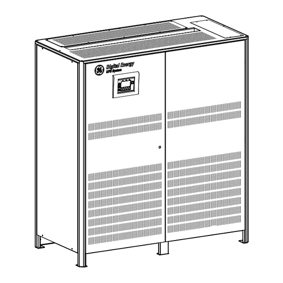
LAYOUT LAYOUT SG Series 225 & 300 Fig. 2.1-1 SG Series 225 & 300 general view Fig. 2.1-2 SG Series 225 & 300 general view with open doors Fig. 2.1-4 Control panel Fig. 2.1-3 Manual operated switches Customer Interface Board UPS output switch Manual Bypass switch (option) SNMP... -
Page 11: Introduction
Tailor made power protection to meet your individual installation requirements; SG Series 225 & 300 offers various options like input harmonic filters and our comprehensive GE Power Diagnostic software suite for mission control and data protection to cover all your application needs. -
Page 12: Description
DESCRIPTION BLOCK DIAGRAM AND MAIN ELEMENTS Fig. 4.1-1 Block diagram The SG Series 225 & 300 system can be divided into the following main elements: Control System SG Series 225 & 300 is designed with microprocessor-controlled signal processing circuits. The interface between the operator and the unit is provided by the monitoring system on the front panel. This monitoring system consists of an active mimic diagram, a keyboard and a backlit display. -
Page 13: Operation Modes
UPS control panel (see Section 7.4 / eBoost). NOTE ! The eBoost™ Operation Mode is available only if enabled at the factory or by a GE GLOBAL SERVICES FIELD ENGINEER. Modifications reserved Page 13/79 OPM_SGS_USM_M22_M30_2US_V010.doc... -
Page 14: Utility Failure Operation
4.2.3 Utility failure operation When the Utility is no longer within acceptable tolerances, the Battery will provide the DC power to the Inverter. The Inverter will maintain continuous AC power to the Load until the Battery Voltage reaches the lower limit of the Inverter operation capability. -
Page 15: Automatic Bypass
4.2.5 Automatic Bypass In normal operation, the Load is supplied by the Inverter. When the control system detects a fault in the Inverter, an overload condition or a short-circuit condition, the Automatic Bypass will transfer the critical Load to the Utility without interruption. When the Inverter recovers, or the overload or short-circuit condition is corrected, the Load will be automatically transferred back to the Inverter. -
Page 16: Parallel System Operation
PARALLEL SYSTEM OPERATION 4.3.1 Introduction to the parallel system Two or more equal power units can be paralleled to increase the output power (paralleling for capacity) or to improve the overall reliability of an UPS system (paralleling for redundancy). The outputs of parallel units are connected to a common power bus, and in normal operation the units connected on the parallel bus share the Load equally. -
Page 17: Features Of Rpa Parallel System
4.3.2 Features of RPA parallel system The SG Series 225 & 300 Parallel System is designed to provide a complete Redundant Parallel Architecture, and is free from common equipment. Not only the Inverters are redundant, but also the Bypass functions are designed with redundant modular concept. -
Page 18: Rectifiers Paralleled On The Same Battery
A parallel system with a Common Battery for two or more Rectifiers, requires a particular installation and adequate setting of some parameters, (accessible only through password), and can therefore only be done by a QUALIFIED ENGINEER from GE. Usually each Rectifier-Inverter Unit runs with its own Battery. -
Page 19: Recycling At The End Of Service Life
RECYCLING AT THE END OF SERVICE LIFE NOTE ! This product has been designed to respect the environment, using materials and components respecting eco-design rules. It does not contain CFCs (chlorofluorocarbons) or HCFCs (hydrochlorofluorocarbons). RECYCLING AT THE END OF SERVICE LIFE ! compliance with environment... -
Page 20: Control Panel
CONTROL PANEL CONTROL PANEL Fig. 5.1-1 Control panel The control panel, positioned on the UPS front door, acts as the UPS user interface and comprises of the following elements: Back lit Graphic Display (LCD) with the following characteristics: • − Multilanguage communication interface: English, German, Italian, Spanish, French, Finnish, Polish, Portuguese, Czech, Slovakian, Chinese, Swedish, Russian and Dutch;... -
Page 21: Table Of Functions And Indications On Control Panel
TABLE OF FUNCTIONS AND INDICATIONS ON CONTROL PANEL Key to switch the Inverter ON ( I ) NOTE ! When eBoost™ Operation Mode is enabled, control of Inverter status and selection of the feed path is done autonomously by the UPS control logic. - Page 22 LED Stop Operation (red color) It warns about the imminent inverter stop (default parameter = 3 min.) and the consequent load shutdown as result of: The battery is fully discharged and the load cannot be transferred on utility. • Overtemperature or overload condition (>125%) and the load cannot be •...
-
Page 23: Lcd Screen
LCD SCREEN HOME SCREEN Fig. 6.1-1 LCD display The buttons perform the following functions: METERING View electric parameters values and statistics of use. METER See Section 6.2. ALARMS Shows in chronological order, all the events occurred (alarms, ALARM messages, commands, handling, etc.). See Section 6.3. MUTE Key to reset general alarm and buzzer. - Page 24 SG Series UPS Model UPS series number UPS nominal rating (kVA) Battery level LED All lightning lit LED open indicate a battery autonomy of 100%. LED A Fixed: indicates a battery autonomy between 6% and 25%. indicates a battery autonomy ≤5%. Blinking: LED A, B Indicate a battery autonomy between 26% and 50%.
-
Page 25: Metering
METERING The METERING mode is entered any time the “METER” button is pressed. The LCD screen will indicate a series of screenshots showing the measures of all electric parameters like AC, DC and various statistics. In this mode the buttons perform the following functions: Return to HOME screen. - Page 26 Inverter data screen Home\Meter INVERTER The output frequency of the Inverter. 60 Hz 277 V Three-phase output voltage PHASE/NEUTRAL. 277 V 277 V The temperature of the inverter bridge. +25° C SYNCHRONIZED The synchronization status of the inverter with respect to utility (SYNCHRONIZED / NOT SYNCHRONIZED).
- Page 27 Home\Meter Statistics screen COUNTERS The total number of bypass utility faults (bypass utility out of tolerance). Bypass utility failure Rectifier utility failure The total number of rectifier utility faults (rectifier utility out Overloads of tolerance). InvOperTime [h] 2135 The total number of detected output overloads. UPSOperTime [h] 3125 The total operating time for the Inverter (in hours).
-
Page 28: Alarms
Confirm the selection made. It is possible to view any pushbutton functional description by pushing the button for more than 3 seconds. The events displayed are the standard GE events as described in the Section 6.3.1 - EVENTS (Alarms and Messages). Home\ Alarm... -
Page 29: Events (Alarms And Messages)
Each of the following listed events, alarm or message, can be displayed on the LCD screen, on a PC with the software “GE Data Protection” installed or with the monitoring system “GE Power Diagnostic”. Alarms and Messages are differently specified because the alarms are indicating an abnormal... - Page 30 Code Alarms Meaning The temperature sensor inside the input transformer winding indicates over temperature. RECTIFIER TRANSFORMER 4106 Only the alarm is given. OVERTEMPERATURE The Rectifier, when in Off state, cannot start as long as this condition persists. RECTIFIER UTILITY OUT Rectifier Input Utility is out of tolerance (voltage, frequency 4110 OF TOLERANCE...
- Page 31 Code Alarms Meaning An abnormal condition has been detected on one or more power modules of the Inverter (temperature or over 4309 DRIVER FAILURE current). Inverter shutdown and cannot be started as long as the alarm is present. Inverter Output Voltage is out of the tolerances (± 10%). INV.
- Page 32 Code Alarms Meaning The UPS-System is in an overload condition >125% on Inverter, or >150% on Utility. 4570 OVERLOAD With Utility unavailable, a sequence of “stop operation” starts. Time out depends on Load quantity. With Utility Bypass supply available and load >115%, the Load is transferred on Utility.
-
Page 33: Messages List
6.3.3 Messages list Code Message Meaning The microprocessor has detected an incorrect operation: Transfers the Load on Utility and performs a program 4002 WATCHDOG RESET reset. The Inverter will restart automatically and will supply the Load. The auxiliary contact indicates that the input rectifier 4108 Q4 OPEN switch Q4 has been opened. - Page 34 Code Message Meaning 2 transfers Inverter- Utility have been detected in a short 4534 MULTIPLE LOAD TRANSFER time, (default 30 seconds). Bypass is not available. 4535 BYPASS LOCKED Contactor K6 is open, SSM deactivated. Bypass is enabled. 4536 BYPASS FREE Contactor K6 is closed.
- Page 35 Code Message Meaning Automatic Battery Test is not possible due to: − No Utility Rectifier or Bypass. 4699 BATTERY TEST IMPOSSIBLE − Battery not fully charged. − Load is below 10% or above 80%. Test is postponed for 1 week. Inverter can be started or shutdown by remote control.
-
Page 36: Event Report Sg Series 225 & 300
6.3.4 Event report SG Series 225 & 300 In case of failure or malfunctioning, before calling the nearest Service Center, please note the most important data of your UPS and the most recent events. In order to make the diagnosis easier from our Diagnostic Center we suggest you make a copy of this page, fill it out with the requested data and send it by fax. -
Page 37: Setup
SETUP The SETUP mode is entered any time the “SETUP” button is pressed. This screen allows the user to modify some parameters permitting to adapt some functions of the UPS to his/her needs, described as follows. The LCD will display a series of screens containing the user parameters, accessible without password protection. - Page 38 Setup screen Home\Setup SETUP LEVEL 1 USER Displays a sequence of screens with parameters which can LEVEL 1 USER be user defined. LEVEL 2 SERVICE LEVEL 2 SERVICE Only service is allowed. At this level the parameters access is protected by a code. Date and time screen Home\Setup\User DATE AND TIME...
- Page 39 Home\Setup\User MODEM Modem screen 2 Tel 2 Tel 2 Tel 2 enabled It records the second dial-out number. Tel 3 Tel 2 enabled Tel 3 enabled This parameter Y/N specifies if the second telephone Tel 4 number will be used for dial-out. Tel 4 enabled Tel 3 It records the third dial-out number.
- Page 40 Home\Setup\User LCD Display screen DISPLAY UPS Name The user can choose the name of the UPS model shown on the main page (max. 9 UPS name SG Series characters). Language This parameter allows the choice of Language ENGLISH language used to display the information. Valid choices are: English, German, Italian, Contrast Spanish, French, Finnish, Polish, Portuguese,...
- Page 41 To better understand the eBoost™ programming modes, some typical examples are shown: Example 1: For continuous eBoost™ Operation Mode set the eBoost START times to 00:00 and the eBoost STOP times to 23:59 for all weekdays, but almost 1 day must have 1 minute of VFI programmation: i.e d2 - Sunday 00:00 to 23:58).
- Page 42 Example 5: An equivalent set of parameters for Example 4 is. Weekday - Saturday - Sunday - Monday - Tuesday - Wednesday - Thursday - Friday eBoost START 00:00 00:00 18:00 18:00 06:00 09:00 12:00 eBoost STOP 23:59 20:00 18:00 06:00 06:00 09:00...
-
Page 43: Commands
COMMANDS The COMMANDS mode is entered any time the “CMDS” button is pressed. Allows the user to execute UPS operation commands. In this mode the buttons perform the following functions: Return to HOME screen. Scrolls forward to the next screen. Scrolls forward to the next line. -
Page 44: Operation
START UP AND COMMISSIONING A GE GLOBAL SERVICES FIELD ENGINEER must perform start-up and commissioning of the UPS. Please Contact GE. Global Services at least two weeks prior to schedule start-up and commissioning at 1-800-637- 1738, or by E-mail at pqservice@ge.com... -
Page 45: Procedures For Single Sg Series 225 & 300
PROCEDURES FOR SINGLE SG Series 225 & 300 7.1.1 Start-up of the SG Series 225 & 300 WARNING ! Before proceeding to Turn ON the UPS System, ensure that the AC and DC external isolators are OFF (Pos. O), and prevent their inadverted operation. Ensure that the output load distribution can be powered and all the output isolators are open (Pos. - Page 46 WARNING ! The setup of the UPS configuration parameters must be done only by a GE GLOBAL SERVICES FIELD ENGINEER. The setup of mistaken values could compromise the integrity and reliability of the UPS. In this mode the keys perform the following functions: Confirm the selection made and select the next parameter.
- Page 47 CONFIGURATION screen Save and exit ? Screen to save the configuration of set parameters. Any additional modification of setup parameters can be done only from a GE SERVICE PERSON as it requires an access code. ► Continue Modifications reserved Page 47/79 OPM_SGS_USM_M22_M30_2US_V010.doc...
- Page 48 2. Close the UPS Output Switch Q1 (Pos. I). • The Load is supplied by the Utility through the Automatic Bypass. • Rectifier starts automatically, blinking LED 3 (Rectifier ON) indicates Soft-start. • At the end of Rectifier Soft-start the LED 3 (Rectifier ON) remains lit. The Synoptic Diagram must display the status “LOAD SUPPLIED BY AUTOMATIC BYPASS”.
-
Page 49: Ups Shutdown With Load Transfer On Manual Bypass Q2 (Option)
7.1.2 UPS shutdown with Load transfer on Manual Bypass Q2 (option) NOTE ! Not following this procedure can cause protected loads to shut down! Never close or open either UPS Output Switch Q1 and Manual Bypass switch Q2 (option) with the inverter running! Initial situation: the Load is powered by the Inverter. - Page 50 3. Open the UPS Output Switch Q1 (Pos. O) and then press the “Load Off” button. • The load is now supplied only through the Manual Bypass Q2. • Rectifier shuts down and all output and input Contactors are opened. •...
-
Page 51: From Manual Bypass Q2 (Option) To Normal Function Vfi
7.1.3 From Manual Bypass Q2 (option) to normal function VFI NOTE ! UPS system has been turned OFF following the “Maintenance shutdown (Load on Manual Bypass Q2)” procedure and the Load is still powered by Manual Bypass Q2 (option). The Load must be transferred back to the UPS system. Open the front door and make sure that: The safety screens are fixed in their position. - Page 52 4. Open the Manual Bypass Switch Q2 (Pos. O). • The Load is supplied by the Utility through the Automatic Bypass. • LED 8 (Automatic Bypass ON) is lit and LED 9 (Manual Bypass Q2 ON) turns OFF. The Synoptic Diagram must display the status “LOAD SUPPLIED BY AUTOMATIC BYPASS”.
-
Page 53: Complete Ups Shutdown
7.1.4 Complete UPS shutdown NOTE ! Follow this procedure only in case the UPS system and the Load must be completely powered-down. If eBoost™ option is available, make sure that eBoost™ Operation mode is disabled before starting this procedure. Initial status: Load supplied from Inverter. -
Page 54: Restore To Normal Operation After "Load Off
7.1.5 Restore to normal operation after “Load Off” NOTE ! Make sure the UPS to be status of the activation of “Load Off”, i. e. UPS Output Switch Q1 closed (Pos. I), Manual Bypass Switch Q2 (option) open (Pos. O) and External Battery Switch or Fuses connected (Pos. -
Page 55: Restore To Normal Operation After Epo (Emergency Power Off)
7.1.6 Restore to normal operation after EPO (Emergency Power Off) NOTE ! Make sure the UPS to be status of the activation of EPO, i. e. UPS Output Switch Q1 closed (Pos. I), Manual Bypass Switch Q2 (option) open (Pos. O) and External Battery Switch or Fuses connected (Pos. -
Page 56: Procedures For Sg Series 225 & 300 Parallel System And Parallel System With Common Battery
PROCEDURES FOR SG Series 225 & 300 PARALLEL SYSTEM AND PARALLEL SYSTEM WITH COMMON BATTERY 7.2.1 SG Series 225 & 300 Parallel System start-up WARNING ! Before proceeding to Turn ON the UPS System, ensure that the AC and DC external isolators are OFF (Pos. - Page 57 WARNING ! The setup of the UPS configuration parameters must be done only by a GE GLOBAL SERVICES FIELD ENGINEER. The setup of mistaken values could compromise the integrity and reliability of the UPS. In this mode the keys perform the following functions: Confirm the selection made and select the next parameter.
- Page 58 CONFIGURATION screen Save and exit ? Screen to save the configuration of set parameters. Any additional modification of setup parameters can be done only from a GE SERVICE PERSON as it requires an access code. ► Continue Modifications reserved Page 58/79 OPM_SGS_USM_M22_M30_2US_V010.doc...
- Page 59 Close UPS Output Switch Q1 (Pos. I) on first Unit. • Rectifiers start automatically, blinking LED 3 (Rectifier ON) indicates Soft-start. • At the end of Rectifier Soft-start, the LED 3 (Rectifier ON) remains lit. Synoptic Diagram of first unit Synoptic Diagram of other units 3.
- Page 60 6. Insert the Inverter by pressing the “Inverter ON” ( I ) key on all other units. Do not start the next Inverter until the sequence of the previous ends. • As soon as the output power of the Inverters is sufficient to supply the Load, the output of the units with running Inverter will transfer to Inverter.
-
Page 61: Parallel System Shutdown With Load Transfer On Manual Bypass Q2 (Option)
7.2.2 Parallel System shutdown with Load transfer on Manual Bypass Q2 (option) NOTE ! Not following this procedure can cause protected loads to shut down! Never close or open either UPS Output Switch Q1 and Manual Bypass switch Q2 (option) with the inverter running! Initial situation: the Load is powered by all inverters of the Parallel System. - Page 62 3. Open the UPS Output Switch Q1 (Pos. O) and then press the “Load Off” key on all Units. • The Load is now supplied only through the Manual Bypass Q2 of all Units. • LED 8 (Automatic Bypass ON) turns OFF and LED 9 (Manual Bypass Q2 ON) stays lit. •...
-
Page 63: From Manual Bypass Q2 (Option) To Normal Function Vfi
7.2.3 From Manual Bypass Q2 (option) to normal function VFI NOTE ! UPS Parallel System has been turned OFF following the “Maintenance shutdown (Load on Manual Bypass Q2)” procedure and the Load is still powered by all Manual Bypass Q2 (option). The Load must be transferred back to the UPS Parallel System. - Page 64 4. Repeat the procedures 2 and 3 for each other Unit. • The Rectifiers will start automatically and at the closure of UPS output switch Q1 of the last Unit, the output will be supplied parallel from Automatic Bypass and Manual Bypass Q2 of all UPS units. •...
-
Page 65: Separate A Ups Unit From The Parallel System (System Redundancy)
7.2.4 Separate a UPS Unit from the Parallel System (System Redundancy) NOTE: The Load is powered by the UPS Redundant Parallel System. One UPS unit of the Parallel System has to be turned Off, while the Load is shared between the other units supplying the parallel bus. If eBoost™... - Page 66 Home\Commands COMMANDS 3. Perform the command “Load Off” on the Unit to separate only when the LED 7 (Q1 closed) is Off. RESET TOTAL OFF Perform the command “Load Off” by entering the screen (see Section 7.5): REQUEST TOTAL OFF COMMANDS / REQUEST TOTAL OFF Synoptic Diagram of the unit to separate Synoptic Diagram of other units...
-
Page 67: Reconnect A Ups Unit To A Parallel System
7.2.5 Reconnect a UPS unit to a Parallel System NOTE: The Load is still powered by the other units supplying the Parallel Bus. This UPS unit will be powered on and connected to the Parallel Bus in order to share the Load with each other's. - Page 68 2. Close the UPS Output Switch Q1 (Pos. I) on the Unit to reconnect. • Rectifier starts automatically, blinking LED 3 (Rectifier ON) indicates Soft-start. • At the end of Rectifier Soft-start the LED 3 (Rectifier ON) remains lit. Synoptic diagram of the unit to reconnect Synoptic diagram of other units 3.
-
Page 69: Complete Parallel System Shutdown
7.2.6 Complete Parallel System shutdown NOTE ! Follow this procedure only in case the UPS Parallel System and the Load must be completely powered-down. If eBoost™ option is available, make sure that eBoost™ Operation Mode is disabled before starting the shutdown procedure. Initial situation: The Load is powered by SG Series 225 &... - Page 70 3. Disconnect on all Units the Battery from the UPS by opening (Pos. O) the External Battery Switch or Fuses. • Wait 5 minutes for DC-Link Capacitors discharge. 4. Disconnect the Utility supply on all Units. • Complete power shutdown will OFF the LCD Display Panel. Synoptic Diagram of first unit Synoptic Diagram of other units END OF PROCEDURE...
-
Page 71: Restore To Normal Operation After "Load Off
7.2.7 Restore to normal operation after “Load Off” NOTE ! Make sure the all Units of the Parallel System to be status of the activation of “Load Off”, i. e. UPS Output Switches Q1 closed (Pos. I), Manual Bypass Switches Q2 (option) open (Pos. - Page 72 Insert the Inverter by pressing the “Inverter ON” ( I ) key on first unit. • Soft-start of Inverter, indicated with blinking LED 5 (Inverter available). • At the end of Soft-start the LED 5 (Inverter available) remains lit. • In case of sufficient output power, the output will transfer to Inverter.
-
Page 73: Restore To Normal Operation After Epo (Emergency Power Off)
7.2.8 Restore to normal operation after EPO (Emergency Power Off) NOTE ! Make sure the all units of the Parallel System to be status of the activation of EPO, i. e. UPS Output Switches Q1 closed (Pos. I), Manual Bypass Switches Q2 (option) open (Pos. - Page 74 Insert the Inverter by pressing the “Inverter ON” ( I ) key on first unit. • Soft-start of Inverter, indicated with blinking LED 5 (Inverter available). • At the end of Soft-start the LED 5 (Inverter available) remains lit. • In case of sufficient output power, the output will transfer to Inverter.
-
Page 75: Options
UPS. Based on the leading Intelligent Remote Information System IRIS all GE UPS types as well as 3rd party UPS are supported. Accessing the latest site information via Web and being alerted by Email, SMS or Fax, it enables the user to make timely decisions in case of changing critical conditions. -
Page 76: Connection For Options
AUX. BUZZER yellow/brown Alarm STOP OPERATION Mute Test GE Digital Energy P.S.: The above mentioned colors are suitables only for XY standard cable 8 1/2" in 216mm Fig. 8.3.1-1 Remote Signaling Box connection Terminals X3, X4 and X15 fitted inside the Remote Signaling Box. -
Page 77: Maintenance
A regular maintenance check of your installation guarantees higher reliability of your safe critical power supply. Preventive maintenance work on the UPS can be done only by trained Service technicians. We therefore recommend you sign a Maintenance and Service contract with GE Global Services @ 1- 800-637-1738 9.1.1 Service check If the LED Operation blinking during normal operation, the unit has not been serviced for the last 20,000 hours by a GE trained technician. -
Page 78: Battery
9.1.4 Battery We recommend a periodic Manual Battery Test, especially if the Automatic Battery Test is disabled, in order to verify if the Battery can provide the expected backup time in case of Utility Failure. We recommend this test be performed at least every 3 months, especially if the Battery is not sufficiently discharged during normal operation. -
Page 79: Notes
10 NOTES 10.1 NOTES FORM It is recommended to note in this section Notes, with date and short description all the operations performed on the UPS, as: maintenance, components replacement, abnormal situations, etc. Date Description Done by Modifications reserved Page 79/79 OPM_SGS_USM_M22_M30_2US_V010.doc User Manual SG Series 225 &...
Need help?
Do you have a question about the SG 225 and is the answer not in the manual?
Questions and answers