Table of Contents
Advertisement
Available languages
Available languages
Quick Links
Download this manual
See also:
User Manual
Advertisement
Chapters
Table of Contents

Related Manuals for Bosch BPT-S 5 Hybrid


Summary of Contents for Bosch BPT-S 5 Hybrid
- Page 1 BPT-S 5 Hybrid Installationsanleitung en Installation manual it Manuale d‘installazione...
- Page 2 Deutsch Speichersystem | Installationsanleitung Bosch Power Tec GmbH...
-
Page 3: Table Of Contents
Anforderungen an den Aufstellungsort Sicherheitszeichen am Gerät Sicherheitseinrichtungen Warnhinweise Grundlegende Sicherheitshinweise Technische Beschreibung Lieferumfang Typenschild Systemübersicht Außenansicht (Gehäusetür geöffnet) Außenansicht Komponenten 3.6.1 Gehäuse 3.6.2 Energiemanagementsystem (EMS) 3.6.3 Ein/Aus-Schalter 3.6.4 USB-Anschlüsse 3.6.5 Strangwechselrichter 3.6.6 Batteriekonverter 3.6.7 Lithium-Ionen-Batterie Bosch Power Tec GmbH Speichersystem | Installationsanleitung... - Page 4 6.10 Deckel des Verteilerkastens montieren 6.11 Frontteil montieren 6.11.1 Batteriekonverter und Strangwechselrichter verbinden 6.11.2 Batteriekonverter an Kabelbaum anschließen 6.11.3 Strangwechselrichter an Kabelbaum anschließen 6.12 Batteriemanagementsystem (BMM) anschließen 6.13 Übersicht Erdungsanschlüsse 6.14 Batterieleitung anschließen Speichersystem | Installationsanleitung Bosch Power Tec GmbH...
- Page 5 Speichersystem mit Ethernet-Netzwerk verbinden Abschirmblech montieren Inbetriebnahme Speichersystem einschalten Sprache auswählen Informationsfenster bestätigen Netznorm auswählen Internetverbindung prüfen Zeit und Datum einstellen Einspeisewirkleistung begrenzen Inbetriebnahme abschließen Fehlersuche Bedeutung der LED-Anzeigen Fehlermeldungen Update Speichersystem durchführen Wartung Außerbetriebnahme Entsorgung Bosch Power Tec GmbH Speichersystem | Installationsanleitung...
- Page 6 6 | Inhaltsverzeichnis Deutsch 12.1 Speichersystem 12.2 Batterien Technische Daten Anhang Speichersystem | Installationsanleitung Bosch Power Tec GmbH...
-
Page 7: Einführung
Deutsch Einführung | 7 Einführung Gültigkeit dieser Anleitung Diese Anleitung ist für die baugleichen Speichersysteme BPT-S 5 Hybrid und VS 5 Hybrid gültig. Kurzbeschreibung Das Speichersystem ist ein batteriegestütztes Wechselrichtersystem zur Optimierung des Energieeigenverbrauchs. Es bildet die Schnittstelle zwischen dem Solargenerator, dem öffentlichen Stromnetz und dem Hausnetz. -
Page 8: Funktionen
Verbindung des Speichersystems zum öffentlichen Stromnetz. Netzbetrieb Der Netzbetrieb stellt eine hohe zeitliche Übereinstimmung der Stromerzeugung der PV-Anlage und des Energieeigenverbrauchs im angeschlossenen Hausnetz sicher. Damit steigert sich der Anteil des Energieeigenverbrauchs in dieser Betriebsart. Speichersystem | Installationsanleitung Bosch Power Tec GmbH... - Page 9 Vorteil, wenn die Verbraucher, die im Falle eines Netzausfalls weiter versorgt werden sollen, auf dieser einen Phase liegen. Wenn das öffentliche Stromnetz wieder zur Verfügung steht, schaltet das Speichersystem automatisch in den Netzbetrieb zurück. Bosch Power Tec GmbH Speichersystem | Installationsanleitung...
-
Page 10: Bestimmungsgemäße Verwendung
Räumen mit einer Luftfeuchtigkeit über 70% (Speichersystem hat Schutzklasse IP20) mit anderen als den vom Hersteller empfohlenen Batterien mit anderen als den vom Hersteller gelieferten Bauteilen mit defekten Leitungen mit beschädigtem Gehäuse Speichersystem | Installationsanleitung Bosch Power Tec GmbH... -
Page 11: Normen Und Richtlinien
Gegenstand dieser Anleitung sind Montage, Installation, Inbetriebnahme und Wartung des Gerätes. Zielgruppe Diese Anleitung richtet sich an vom Betreiber beauftragte Elektrofachkräfte. Bedienschritte Bedienschritte werden mit einem Dreieck eingeleitet und einem Quadrat als Ergebnis der Handlung abgeschlossen. Bosch Power Tec GmbH Speichersystem | Installationsanleitung... -
Page 12: Abkürzungen
Tabellen-Aufzählungen / Aufzählungen der 2. Ebene Info Zusätzliche Informationen oder Tipps Kursiv LED-Anzeigen, Texte im Display, Querverweise Abkürzungen Abkürzung Bedeutung Alternating Current (Wechselstrom) Batteriemanagement Batteriekonverter Direct Current (Gleichstrom) Energiemanagementsystem Photovoltaik Seriennummer der jeweiligen Komponente Speichersystem | Installationsanleitung Bosch Power Tec GmbH... -
Page 13: Sicherheit
Gefahrenquellen informiert und die nötigen Sicherheitsmaßnahmen ergriffen werden die Anleitung und insbesondere die Sicherheitshinweise von den beauftragten Personen gelesen und verstanden werden die Anleitung während des Transports, der Montage, Installation und Inbetriebnahme verfügbar Bosch Power Tec GmbH Speichersystem | Installationsanleitung... -
Page 14: Elektrofachkraft
Schutzeinrichtungen entsprechend festgelegten Sicherheitsstandards. Die Notversorgung von Verletzten. Die einschlägigen Normen, Richtlinien und lokalen Vorschriften. Das Arbeiten mit Gleichstrom und dabei beachtet: – Die Stromquelle der PV-Anlagen ist bei Tageslicht immer aktiv. Speichersystem | Installationsanleitung Bosch Power Tec GmbH... -
Page 15: Pflichten
Der Kurzschlussstrom des Solargenerators ist nur etwas höher als der maximale Betriebsstrom und ist immer abhängig von der aktuellen Einstrahlung. Daher ist bei Kurzschlüssen das Abschalten der vorhandenen Sicherungen nicht immer gewährleistet. Bosch Power Tec GmbH Speichersystem | Installationsanleitung... -
Page 16: Anforderungen An Den Aufstellungsort
– Raum von 8...25 m³: passive oder aktive Lüftung notwendig (bei 8 m³: Luftwechselrate von 12 m³/ – Raum über 25 m³: keine gesonderten Lüftungsmaßnahmen – Grundfläche min. 2,00 m² – Höhe min. 2,00 m – Tiefe min. 2,00 m Speichersystem | Installationsanleitung Bosch Power Tec GmbH... - Page 17 – Verschmutzungsgrad 2 für Umgebung des Speichersystems – Gemäß DIN EN 60664 wird der Verschmutzungsgrad 2 wie folgt definiert: Es tritt gewöhnlich nur nicht-leitfähige Verschmutzung auf; gelegentlich muss jedoch mit vorübergehender Leitfähigkeit durch Betauung gerechnet werden. Bosch Power Tec GmbH Speichersystem | Installationsanleitung...
-
Page 18: Sicherheitszeichen Am Gerät
Sicherheitszeichen am Gerät Gefahr eines elektrischen Schlages Warnung vor dem möglichen Auslaufen der Batterien Risiko eines elektrischen Schlages Zeitspanne zur Entladung beträgt 13 Minuten 13 min Installationsanleitung und Bedienungsanleitung lesen Gehäuse und Batterien nicht anbohren Speichersystem | Installationsanleitung Bosch Power Tec GmbH... -
Page 19: Sicherheitseinrichtungen
Verhinderung von Verletzungen oder Sachschaden Die Warnhinweise sind nach folgenden Gefahrenstufen klassifiziert: Kennzeichnet eine außergewöhnlich große GEFAHR Gefahrensituation Dieser Warnhinweis steht für eine unmittelbar drohende Gefahr, die zu schweren Körperverletzungen oder zum Tod führt. Warnhinweis beachten Bosch Power Tec GmbH Speichersystem | Installationsanleitung... -
Page 20: Grundlegende Sicherheitshinweise
(Kontaktdaten auf der Rückseite der Anleitung). Lebensgefahr: Allgemein Lebensgefahr durch fehlende Hilfe GEFAHR Bei einem Unfall kann eine zweite Person die Stromzufuhr abschalten und Hilfe leisten. Nur in Anwesenheit einer zweiten Person arbeiten. Speichersystem | Installationsanleitung Bosch Power Tec GmbH... - Page 21 Anlage bei Tageslicht immer aktiv ist. Vor Beginn aller Arbeiten an elektrischen Anlagen: Freischalten Gegen Wiedereinschalten sichern Spannungsfreiheit feststellen Erden und kurzschließen Benachbarte, unter Spannung stehende Bauteile abdecken oder abschranken Bosch Power Tec GmbH Speichersystem | Installationsanleitung...
- Page 22 Alle externen und internen Trenneinrichtungen öffnen und gegen Wiedereinschaltung sichern Nach Abschalten des Gerätes immer eine zusätzliche Wartezeit von 13 Minuten einhalten Spannungsfreiheit mit einem passenden Messgerät entsprechend den dafür geltenden Richtlinien kontrollieren Speichersystem | Installationsanleitung Bosch Power Tec GmbH...
- Page 23 Ausschließlich Werkzeuge mit isolierten Griffen verwenden Keine Werkzeuge oder andere metallische Gegenstände auf den Batterien ablegen oder lagern Immer zuerst Be- und Entladequellen entfernen und dann an den Batterieanschlüssen arbeiten Bosch Power Tec GmbH Speichersystem | Installationsanleitung...
- Page 24 WARNUNG Komponenten des Gerätes können bis zu 100 °C warm werden und zu schweren Verbrennungen führen. Nach Abschalten des Gerätes eine zusätzliche Wartezeit von 13 Minuten einhalten Heiße Komponenten nicht berühren Speichersystem | Installationsanleitung Bosch Power Tec GmbH...
- Page 25 Schutzhandschuhe tragen Komponenten mit 2 Personen montieren Verletzungsgefahr: Batterie Verletzungsgefahr durch unsachgemäße WARNUNG Handhabung der Batterien Augen- und Hautverletzung durch Öffnen oder Beschädigung der Batterien. Batterien nie öffnen oder beschädigen Bosch Power Tec GmbH Speichersystem | Installationsanleitung...
- Page 26 Sachschaden durch abweichende technische Daten HINWEIS Das Gerät ist ausschließlich für den Betrieb unter Einhaltung der technischen Daten konzipiert. Unter abweichenden Bedingungen ist das Produkt gefährdet und es kann zu Einspeiseverlusten kommen. Technische Daten einhalten Speichersystem | Installationsanleitung Bosch Power Tec GmbH...
-
Page 27: Technische Beschreibung
Kontrollieren Sie unmittelbar nach dem Auspacken des Speichersystems den Lieferumfang. Wenn Bauteile fehlen oder Beschädigungen aufweisen, setzen Sie sich unverzüglich mit dem Hersteller in Verbindung. Im Lieferumfang sind standardmäßig die folgenden Komponenten enthalten: Bosch Power Tec GmbH Speichersystem | Installationsanleitung... - Page 28 M5 Spannschreiben für Abdeckung der Anschlussleiste Linsenkopfschrauben (M5 X 10) für Abdeckung der Anschlussleiste Hälften des Bodenschutzblechs Komponenten im Beipack Menge Komponente Label Battery Capacity installed 4,4 kWh Label Battery Capacity installed 6,6 kWh Speichersystem | Installationsanleitung Bosch Power Tec GmbH...
- Page 29 Kabel 2W22, für Batteriekonverter und BMM Innensechskantschrauben (M6 X 12) und K- Scheiben für Wechselrichter Linsenkopfschrauben (M4 X 8) für BMM M4 Spannscheiben für BMM Lithium-Ionen-Batterien Zubehör der Lithium-Ionen-Batterien: mehrere Flachbandleitungen, Stromkabel und Kommunikationskabel Batteriemanagement (BMM) Batteriekonverter Wechselrichter Bosch Power Tec GmbH Speichersystem | Installationsanleitung...
-
Page 30: Typenschild
Das Typenschild für das Speichersystem ist hinter der Gehäusetür. Je nach Anzahl der eingebauten Batterien ist die Speicherkapazität des Speichersystems: 4,4 kWh 6,6 kWh 8,8 kWh 11 kWh oder 13,2 kWh Speichersystem | Installationsanleitung Bosch Power Tec GmbH... - Page 31 Battery Capacity 8.8 kWh Installed 3.1: Typenschild Speichersystem Gerätebezeichnung Hersteller DC-Eingang Eingangsdaten des Solargeneratoranschlusses: Maximaler Strom, maximale Spannung, MPP- Eingangsbereich Spannung der Batterien Speicherkapazität der Batterien Batterientyp Ausgangsdaten des Netzanschlusses AC-Backup Control Line Bosch Power Tec GmbH Speichersystem | Installationsanleitung...
-
Page 32: Systemübersicht
Das Speichersystem steuert den Fluss der von der PV-Anlage erzeugten Energie. Es ist zwischen der PV Anlage, dem Hausnetz sowie dem öffentlichen Stromnetz eingebunden. Funktionsübersicht Das Speichersystem funktioniert zu den einzelnen Tageszeiten wie in den folgenden Beispielen dargestellt. Speichersystem | Installationsanleitung Bosch Power Tec GmbH... - Page 33 Die im PV-Generator produzierte Energie wird vorrangig zur Optimierung des Eigenverbrauchs genutzt. Überschüssige Energie wird zum Aufladen der integrierten Lithium-Ionen-Batterien genutzt. 3.2: Vormittags: Energie zum Eigenverbrauch und für Batterien PV-Generator Speichersystem Lithium-Ionen-Batterien Verteilung und Zähler Bosch Power Tec GmbH Speichersystem | Installationsanleitung...
- Page 34 Bei voll aufgeladenen Batterien wird die erzeugte Energie zum Eigenverbrauch genutzt. Überschüssige Energie wird in das öffentliche Stromnetz eingespeist. 3.3: Nachmittags: Einspeisung der überschüssigen Energie ins Netz PV-Generator Speichersystem Lithium-Ionen-Batterien Verteilung und Zähler Speichersystem | Installationsanleitung Bosch Power Tec GmbH...
- Page 35 Abends Nach Sonnenuntergang stellt das Speichersystem die in den Batterien gespeicherte Energie zur Verfügung. Damit unterstützt das Speichersystem den Energieeigenverbrauch. 3.4: Abends: Energie aus Batterie zum Eigenverbrauch PV-Generator Speichersystem Lithium-Ionen-Batterien Verteilung und Zähler Bosch Power Tec GmbH Speichersystem | Installationsanleitung...
- Page 36 Sollte die Kapazität der Batterien für den Eigenbedarf nicht ausreichen, wird zusätzlich Strom aus dem öffentlichen Stromnetz bezogen. 3.5: Nachts: Versorgung durch öffentliches Netz, da Batterie leer PV-Generator Speichersystem Lithium-Ionen-Batterien Verteilung und Zähler Speichersystem | Installationsanleitung Bosch Power Tec GmbH...
-
Page 37: Außenansicht (Gehäusetür Geöffnet)
Deutsch Technische Beschreibung | 37 Außenansicht (Gehäusetür geöffnet) 3.6: Außenansicht Speichersystem mit geöffneter Gehäusetür Bosch Power Tec GmbH Speichersystem | Installationsanleitung... -
Page 38: Außenansicht
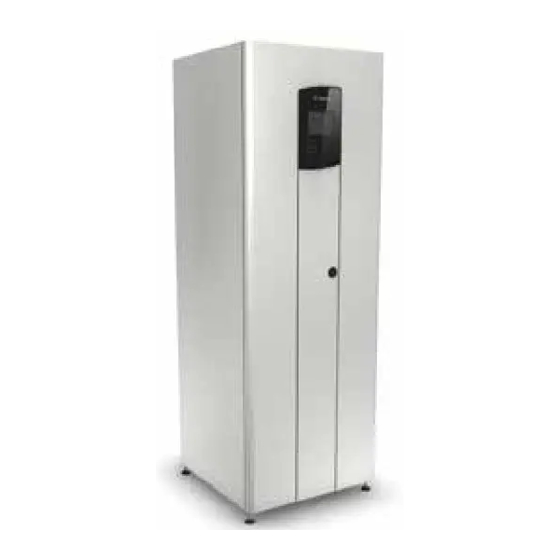
Speichersystems an das Hausnetz Zugentlastung Befestigung der Leitungen der externen Verbindung Schutzblech Dient der Feuerfestigkeit des Gerätes Außenansicht Das Gehäuse des Speichersystems bildet eine abgeschlossene Einheit. Gesichert wird das Gerät mit einem Kippschutz an der Wand. Speichersystem | Installationsanleitung Bosch Power Tec GmbH... - Page 39 Deutsch Technische Beschreibung | 39 3.7: Außenansicht Speichersystem Rückwand Mit integriertem Luftabzugsschacht, der für eine kontinuierliche Belüftung und Kühlung des Speichersystems sorgt Bosch Power Tec GmbH Speichersystem | Installationsanleitung...
-
Page 40: Komponenten
Teil des Gehäuses. Die Batterieabdeckung trennt als Sicherheitsbereich die Batterien von den anderen Komponenten. 3.6.2 Energiemanagementsystem (EMS) Das Energiemanagementsystem (EMS) ist die Bedieneinheit des Speichersystems. Das EMS finden Sie vormontiert im Frontteil des Speichersystems. Speichersystem | Installationsanleitung Bosch Power Tec GmbH... - Page 41 Sie von einem Inbetriebnahme-Assistenten geführt (siehe Kapitel Inbetriebnahme). Nach erfolgreicher Inbetriebnahme öffnet sich das Startfenster des Speichersystems. Wie Sie weitere Einstellungen im Speichersystem vornehmen oder Daten abfragen, entnehmen Sie bitte der separaten Bedienungsanleitung. Bosch Power Tec GmbH Speichersystem | Installationsanleitung...
- Page 42 42 | Technische Beschreibung Deutsch 3.8: Startfenster des EMS Speichersystem | Installationsanleitung Bosch Power Tec GmbH...
- Page 43 Systemstatus Passwortschutz Aktueller System abschalten System abschalten Aktueller Systemstatus Systemstatus 3.9: Menüstruktur des EMS Display und LED-Anzeigen EMS Die LED-Anzeigen geben Auskunft über den Status des Speichersystems und der im Gerät angeschlossenen Komponenten. Bosch Power Tec GmbH Speichersystem | Installationsanleitung...
-
Page 44: Ein/Aus-Schalter
LED: Grid Netzzuschaltung LED: Fault Störungsanzeige 3.6.3 Ein/Aus-Schalter Der Ein/ Aus-Schalter des Speichersystems befindet sich hinter der Gehäusetür des Frontteils im Gehäuse. Mit diesem Schalter schalten Sie die Komponenten des Speichersystems ein oder aus. Speichersystem | Installationsanleitung Bosch Power Tec GmbH... -
Page 45: Usb-Anschlüsse
Strangwechselrichter Der Strangwechselrichter des Speichersystems wandelt den Gleichstrom aus der PV-Anlage und/ oder den Batterien in Wechselstrom um liefert PV-Energie für den Eigenverbrauch oder für die Einspeisung in das öffentliche Stromnetz Bosch Power Tec GmbH Speichersystem | Installationsanleitung... -
Page 46: Batteriekonverter
Der Batteriekonverter im Speichersystem wandelt beim Laden der Batterie den Gleichstrom des Solargenerators in batteriekonformen Gleichstrom um wandelt bei der Stromentnahme aus der Batterie den Gleichstrom in Strangwechselrichter- konformen Gleichstrom um Speichersystem | Installationsanleitung Bosch Power Tec GmbH... -
Page 47: Lithium-Ionen-Batterie
Sie können bis zu 6 Batterien in dem Speichersystem einbauen. Je nach installierter Anzahl der Batterien kann eine Batteriekapazität von 4,4 kWh / 6,6 kWh / 8,8 kWh / 11 kWh oder 13,2 kWh erreicht werden. Bosch Power Tec GmbH Speichersystem | Installationsanleitung... -
Page 48: Batteriemanagementmodul (Bmm)
Batterie überwacht Be- und Entladung der Batterie kommuniziert mit den Batterien und dem EMS 3.16: Anschluss-Seite des Batteriemanagementmoduls Battery Power Gekennzeichnet mit rotem Punkt Battery Converter Gekennzeichnet mit gelbem Punkt Speichersystem | Installationsanleitung Bosch Power Tec GmbH... -
Page 49: Anschlussleiste
InverterSetup). Bei Auslieferung ist ein Abschlusswiderstand auf diesem Anschluss gesteckt. CAN Open Anschluss für den PV-Sensor (optional) Anschluss Ethernet-Netzwerk RS485 Anschluss für den Energiezähler Anschluss für USB Stick z. B. Update der Firmware Bosch Power Tec GmbH Speichersystem | Installationsanleitung... - Page 50 50 | Technische Beschreibung Deutsch Speichersystem | Installationsanleitung Bosch Power Tec GmbH...
-
Page 51: Ablaufplan
– Komponenten installieren und anschließen – Außenteile montieren – Abschirmblech demontieren Externe Externe Verkabelung, Verkabelung S. 103 – An das Hausnetz anschließen – Externe Komponenten anschließen – Abschirmblech montieren – Inbetriebnahme-Assistent Inbetriebnahme Inbetriebnahme, S. 115 Bosch Power Tec GmbH Speichersystem | Installationsanleitung... - Page 52 52 | Ablaufplan Deutsch Speichersystem | Installationsanleitung Bosch Power Tec GmbH...
-
Page 53: Anlieferung Und Aufstellung
Beim Einbau und Ausbau sowie beim Transport der Komponenten kann es aufgrund des hohen Eigengewichts der Komponenten zu Verletzungen kommen. Komponenten mit 2 Personen montieren und transportieren Vor den Transport an den Aufstellungsort Gehäuse demontieren Bosch Power Tec GmbH Speichersystem | Installationsanleitung... -
Page 54: Speichersystem Auspacken (Monteur)
Gerät mit mindestens 2 Personen transportieren 1. Speichersystem an den ausgewählten Aufstellungsort transportieren ■ Speichersystem ist durch den Transporteur angeliefert. Speichersystem auspacken (Monteur) ▶ Vorgehensweise 1. Verpackung vom Gehäuse und von den Komponenten entfernen und entsorgen. Speichersystem | Installationsanleitung Bosch Power Tec GmbH... -
Page 55: Gehäuse-Füße Montieren
1. Gehäuse auf die rechte Seite kippen 2. Rechte Seite: Beide Stutzen auf 63,5 mm herausziehen Auf diese Weise ergibt sich ein Abstand von 50 mm zwischen der Unterseite des Speichersystems und dem Schutzblech. Bosch Power Tec GmbH Speichersystem | Installationsanleitung... - Page 56 3. Jeweils einen Gehäuse-Fuß auf den vorderen und hinteren Stutzen des Gehäuses stecken 5.2: Gehäuse-Fuß auf Stutzen stecken 4. Gehäuse auf die linke Seite kippen 5. Schritte 2 und 3 für die linke Seite wiederholen ■ Gehäuse-Füße sind montiert. Speichersystem | Installationsanleitung Bosch Power Tec GmbH...
-
Page 57: Gehäuse Aufstellen
Abstand von 1,0 m ≥ 0,20 m ≤ 0,15 m ≥ 0,50 m ≥ 0,50 m 5.3: Ausrichtung des Speichersystems ■ Das Gehäuse ist aufgestellt und ausgerichtet. Bosch Power Tec GmbH Speichersystem | Installationsanleitung... - Page 58 58 | Anlieferung und Aufstellung Deutsch Speichersystem | Installationsanleitung Bosch Power Tec GmbH...
-
Page 59: Installation
Sicherheitshinweise beachten Verletzungsgefahr durch scharfe Kanten WARNUNG Die Komponenten verfügen über scharfe Kanten, die bei unvorsichtiger Handhabung zu Verletzungen der Hände führen können. Schutzhandschuhe tragen Komponenten mit 2 Personen montieren Bosch Power Tec GmbH Speichersystem | Installationsanleitung... -
Page 60: Gehäuseaußenteile Demontieren
Die vorderen und seitlichen Außenteile des Gehäuses (Verkleidungen) demontieren Zusätzlich müssen Sie das Lüftungsgitter und die Batterieabdeckung aus dem Gehäuse entfernen. 6.2.1 Gehäusedeckel demontieren ▶ Vorgehensweise 1. Oberseite des Gehäuses: 8 M6- Senkkopfschrauben mit 4er-Inbusschlüssel lösen Speichersystem | Installationsanleitung Bosch Power Tec GmbH... - Page 61 Deutsch Installation | 61 6.1: Verschraubungen des Gehäusedeckels 2. M5-Sechskantmutter der Erdungsleitung mit 8er- Schlüssel lösen 3. Erdungsleitung lösen 6.2: Verschraubung der Erdungsleitung Bosch Power Tec GmbH Speichersystem | Installationsanleitung...
-
Page 62: Seitenteile Demontieren
Seitenteile demontieren ▶ Vorgehensweise 1. Innenseite des Gehäuses: Oben die 3 M5- Sechskantmuttern mit 8er-Schlüssel lösen Muttern des Seitenteils (1) lösen 6.3: 2. Außenseite des Gehäuses: 2 M5- Linsenkopfschrauben und Unterlegscheiben mit 3er-Inbusschlüssel lösen Speichersystem | Installationsanleitung Bosch Power Tec GmbH... - Page 63 6.4: Verschraubungen lösen und Seitenteil herausheben 3. Seitenteil aus der unteren Halterung heben 4. Seitenteil kippsicher zur Seite stellen 5. Schritte 1 bis 4 für das andere Seitenteil wiederholen ■ Seitenteile sind demontiert. Bosch Power Tec GmbH Speichersystem | Installationsanleitung...
-
Page 64: Frontteil Demontieren
64 | Installation Deutsch 6.2.3 Frontteil demontieren ▶ Vorgehensweise 1. Innenseite des Gehäuse: Jeweils rechts und links die mittigen und unteren M5-Sechskantmuttern mit 8er-Schlüssel lösen 6.5: Im Gehäuse untere und mittige Verschraubungen lösen Speichersystem | Installationsanleitung Bosch Power Tec GmbH... - Page 65 2. Oben die 2 M6-Zylinderkopfschrauben mit einem 5er-Inbusschlüssel lösen 6.6: Obere Verschraubungen lösen 3. Unten im Türkanal: 2 M6-Zylinderkopfschrauben mit 5er-Inbusschlüssel lösen 4. Im Türkanal, unterhalb EMS: 2 M5- Zylinderkopfschrauben mit 4er-Inbusschlüssel lösen Bosch Power Tec GmbH Speichersystem | Installationsanleitung...
-
Page 66: Lüftungsgitter Demontieren
6. Frontteil kippsicher zur Seite stellen ■ Frontteil ist demontiert. 6.2.4 Lüftungsgitter demontieren ▶ Vorgehensweise 1. 11 M5-Zylinderkopfschraube des Lüftungsgitters mit 4er-Inbusschlüssel lösen 2. Lüftungsgitter aus dem Gehäuse nehmen 3. Lüftungsgitter zur Seite stellen Speichersystem | Installationsanleitung Bosch Power Tec GmbH... -
Page 67: Batterieabdeckung Demontieren
Deutsch Installation | 67 6.8: Lüftungsgitter demontieren ■ Das Lüftungsgitter ist demontiert. 6.2.5 Batterieabdeckung demontieren ▶ Vorgehensweise 1. Seitlich der Batterieabdeckung: 4 M6- Seckskantmuttern mit 10er-Schlüssel lösen Bosch Power Tec GmbH Speichersystem | Installationsanleitung... -
Page 68: Gehäuse Kippsicher Befestigen
2. Batterieabdeckung schräg nach oben und vorne aus dem Gehäuse ziehen ■ Batterieabdeckung ist demontiert. Gehäuse kippsicher befestigen Voraussetzung Kippschutz ist auf der Rückwand des Gehäuse montiert Abstände des Gerätes sind kontrolliert (Gehäuse aufstellen, S. 57) Speichersystem | Installationsanleitung Bosch Power Tec GmbH... -
Page 69: Batterien Einbauen Und Anschließen
■ Gehäuse ist kippsicher befestigt. Batterien einbauen und anschließen Beachten Sie die Informationen zu den Batterien in der separaten dem Speichersystem beigelegten Anleitung des Batterieherstellers Saft: Synerion®- Speichersystem 4,4 kWh bis 13,2 kWh Bosch Power Tec GmbH Speichersystem | Installationsanleitung... - Page 70 Batterietypen verwendet werden, können die Batterien explodieren. Nur vom Hersteller zugelassene Batterien verwenden Verletzungsgefahr durch unsachgemäße WARNUNG Handhabung der Batterien Augen- und Hautverletzung durch Öffnen oder Beschädigung der Batterien. Batterien nie öffnen oder beschädigen Speichersystem | Installationsanleitung Bosch Power Tec GmbH...
- Page 71 3. Die lange Flachbandleitung (1) an der obersten Batterie anschließen 4. Batterien mit den kurzen Flachbandleitungen (2) verbinden Leitungen jeweils unten und oben an der Vorderseite der Batterien anschließen 5. Abschlusswiderstand (3) am unteren Abschluss anschließen Bosch Power Tec GmbH Speichersystem | Installationsanleitung...
- Page 72 72 | Installation Deutsch 6.12: Flachbandleitungen und Abschlusswiderstand anschließen 6. Batterieleitung an jede Batterie anschließen Speichersystem | Installationsanleitung Bosch Power Tec GmbH...
-
Page 73: Batterieabdeckung Montieren
1. Batterieabdeckung so über die Batterien stülpen, dass die 4 Gewindebolzen der Rückwand des Gehäuses in die Bohrungen der Batterieabdeckung greifen. 2. Batteriekommunikationsleitung und Batterieleitung oben aus den Öffnungen der Batterieabdeckung (1) herausführen Bosch Power Tec GmbH Speichersystem | Installationsanleitung... - Page 74 Anziehdrehmomente, S. 145) 3. Batterieabdeckung mit den 4 M6- Sechskantmuttern und Unterlegscheiben mit 10er- Schlüssel festschrauben (Anziehdrehmoment 2,7 4. Batterieabdeckung mit einer Erdungsleitung erden Batterieabdeckung verschrauben (1) und (2) 6.14: ■ Batterieabdeckung ist montiert. Speichersystem | Installationsanleitung Bosch Power Tec GmbH...
-
Page 75: Lüftungsgitter Montieren
Die Federn des Gitters zeigen in den Innenraum des Speichersystems. 6.15: Lüftungsgitter verschrauben 2. Lüftungsgitter vorne und hinten mit den 11 M5- Zylinderkopfschrauben und Unterlegscheiben mit 4er-Inbusschlüssel verschrauben (Anziehdrehmoment 2,7 Nm) ■ Das Lüftungsgitter ist montiert. Bosch Power Tec GmbH Speichersystem | Installationsanleitung... -
Page 76: Batteriemanagementmodul (Bmm) Montieren
Anschlüsse des BMM zeigen nach oben ▶ Vorgehensweise 1. BMM mit 4 M4-Linsenkopfschrauben und Unterlegscheiben mit 2,5er Inbusschlüssel so an der Halterung der Batterieabdeckung schrauben, dass die Anschlüsse des Moduls nach oben zeigen. (Anziehdrehmoment 0,5 Nm) Speichersystem | Installationsanleitung Bosch Power Tec GmbH... - Page 77 Deutsch Installation | 77 6.16: BMM an Halterung der Batterieabdeckung schrauben ■ Batteriemanagementmodul (BMM) ist montiert. Bosch Power Tec GmbH Speichersystem | Installationsanleitung...
-
Page 78: Batteriekonverter
1. Im Gehäuse: Batteriekonverter schräg nach oben schieben und Batteriekonverter senkrecht vorsichtig herunterlassen. Linke und rechte Lasche am Batteriekonverter (1) in die Halterungen im Gehäuse (2) schieben. 2. Batteriekonverter unten: 2 M6- Zylinderkopfschrauben mit 5er-Inbusschlüssel festschrauben (Anziehdrehmoment 2,7 Nm) Speichersystem | Installationsanleitung Bosch Power Tec GmbH... -
Page 79: An Internen Verteilerkasten Anschließen
2. 2-adrige Backup Leitung (1) an die unteren Klemmen 5 und 6 des internen Verteilerkastens (M20) anschließen 3. 4-adrige Zwischenkreisleitung (DC Link) (2) an die unteren Klemmen 1-4 des internen Verteilerkastens (M25) anschließen Bosch Power Tec GmbH Speichersystem | Installationsanleitung... - Page 80 Klemmen 1-4; 2-adrige Leitung an Klemmen 5-6 Info Die Kupferfolie an den Leitungen muss zu gleichen Teilen an den Durchführungen oben und unten sichtbar sein (wichtig für EMV-Schutz). 4. EMV-Verschraubung festziehen ■ Batteriekonverter ist an internen Verteilerkasten angeschlossen. Speichersystem | Installationsanleitung Bosch Power Tec GmbH...
-
Page 81: Strangwechselrichter
Komponenten mit 2 Personen montieren 6.9.1 Montieren ▶ Vorgehensweise 1. Im Gehäuse oben links: Beide Zapfen des Strangwechselrichters einhängen 2. Strangwechselrichter unten: 1 M6- Zylinderkopfschraube und Unterlegscheibe mit 5er Inbusschlüssel festschrauben (Anziehdrehmoment 2,7 Nm) Bosch Power Tec GmbH Speichersystem | Installationsanleitung... -
Page 82: An Internen Verteilerkasten Anschließen
Anziehdrehmomente, S. 145) ▶ Vorgehensweise 1. 2-adrige Backup-Leitung (1) an die oberen Klemmen 5 und 6 des internen Verteilerkastens anschließen 2. 4-adrige Zwischenkreisleitung (DC Link) (2) an die oberen Klemmen 1-4 des internen Verteilerkastens anschließen Speichersystem | Installationsanleitung Bosch Power Tec GmbH... - Page 83 Klemmen 1-4; 2-adrige Leitung an Klemmen 5-6 Info Kupferfolie an den Leitungen muss zu gleichen Teilen an den Durchführungen oben und unten sichtbar sein (wichtig für EMV-Schutz). 3. EMV-Verschraubung festziehen 4. Verschaltung der Leitungen kontrollieren Bosch Power Tec GmbH Speichersystem | Installationsanleitung...
-
Page 84: Deckel Des Verteilerkastens Montieren
Sechskantmutter und Unterlegscheibe mit 8er- Schlüssel an der markierten Stelle des Gehäuses festschrauben 4. Frontteil auf der Innenseite des Gehäuses auf beiden Seiten unten und mittig mit je 2 M5- Sechskantmuttern und Unterlegscheibe mit 8er- Schlüssel festschrauben Speichersystem | Installationsanleitung Bosch Power Tec GmbH... - Page 85 Frontteil erden (2) und verschrauben (1) 6.23: 5. Unten im Türkanal (3): 2 M6- Zylinderkopfschrauben mit 5er-Inbusschlüssel festschrauben 6. Im Türkanal, unterhalb des EMS (4): 2 M5- Zylinderkopfschrauben und Unterlegscheiben mit 4er-Inbusschlüssel festschrauben (Anziehdrehmoment 2,7 Nm) Bosch Power Tec GmbH Speichersystem | Installationsanleitung...
- Page 86 86 | Installation Deutsch 6.24: Türkanal: Frontteil festschrauben 7. Frontteil oben mit 2 M6- Zylinderkopfschrauben mit 5er-Inbusschlüssel festschrauben (Anziehdrehmoment 2,7 Nm) Speichersystem | Installationsanleitung Bosch Power Tec GmbH...
-
Page 87: Batteriekonverter Und Strangwechselrichter Verbinden
6.11.1 Batteriekonverter und Strangwechselrichter verbinden ▶ Vorgehensweise 1. CAN-Leitung (im Lieferumfang enthalten) an CAN Out des Batteriekonverters und an CAN In des Strangwechselrichters anschließen CAN In Strangwechselrichter (1) und CAN Out 6.26: Batteriekonverter (2) Bosch Power Tec GmbH Speichersystem | Installationsanleitung... -
Page 88: Batteriekonverter An Kabelbaum Anschließen
24-V-Anschluss Nr. 3 Hilfsversorgung BAT+ Anschluss (blauer Punkt) BAT- Anschluss (blauer Punkt) [10] AC-Backupleitung ▶ Vorgehensweise 1. 24-V-Versorgung des BMM an den Anschluss (6) anschließen 2. 24-V-Versorgung des Batterieschalters an den Anschluss (5) anschließen Speichersystem | Installationsanleitung Bosch Power Tec GmbH... -
Page 89: Strangwechselrichter An Kabelbaum Anschließen
8. Kabel an den Anschluss BAT- (9) (blauer Anschlusspunkt auf dem Batteriekonverter) anschließen ■ Batteriekonverter ist an den Kabelbaum angeschlossen. 6.11.3 Strangwechselrichter an Kabelbaum anschließen (3) (4) (5) (1) (2) 6.28: Anschlüsse Strangwechselrichter DC + DC - Bosch Power Tec GmbH Speichersystem | Installationsanleitung... - Page 90 (grüner Punkt am Anschluss des Strangwechselrichters) 3. Leitung CAN In des Batteriekonverters an den CAN In Anschluss (3) des Strangwechselrichters anschließen 4. CAN Out anschließen 5. AC-Out anschließen ■ Strangwechselrichter ist am Kabelbaum angeschlossen. Speichersystem | Installationsanleitung Bosch Power Tec GmbH...
-
Page 91: Batteriemanagementsystem (Bmm) Anschließen
1. Leitung (Kabelbaum Frontteil) an DC Input anschließen 2. CAN Leitung des Anschlusses Extension am EMS an eine der beiden CAN anschließen 3. Leitung des PV-Sensors (optional) an den anderen CAN anschließen 4. Batteriekommunikationsleitung an Internal Battery Bus anschließen Bosch Power Tec GmbH Speichersystem | Installationsanleitung... -
Page 92: Übersicht Erdungsanschlüsse
– Erdungsleitung an der gekennzeichneten Stelle am schwarzen Abschirmblech im Türkanal befestigen Türkanal zur Tür Kabel 2W20 Gehäuse zur Montageplatte Kabel 2W19 (Anschlussleiste) Gerätedeckel zum Gehäuse Kabel 2W21 Rückwand zum Gehäuse Kabel 2W13 Speichersystem | Installationsanleitung Bosch Power Tec GmbH... -
Page 93: Batterieleitung Anschließen
Batterieleitung mit den Anschlüssen BAT+ und BAT- Battery Power des BMM verbinden BMM: Batterieleitung an BAT+(1) und BAT- (2) 6.30: Messungen gemäß DIN EN 62446 durchführen, um sicherzustellen, dass die Komponenten korrekt angeschlossen sind. Bosch Power Tec GmbH Speichersystem | Installationsanleitung... -
Page 94: Gehäuseaußenteile Montieren
Einbau an den dafür markierten Stellen erden 6.15.1 Erdungsleitungen Montageplatte / Türkanal montieren ▶ Vorgehensweise 1. Erdungsleitung Kabel 2W19 zwischen Montageplatte (Anschlussklemmen) und Gehäuse montieren 2. Erdungsleitung Kabel 2W15 zwischen Türkanal und Gehäuse montieren Speichersystem | Installationsanleitung Bosch Power Tec GmbH... -
Page 95: Seitenteile Montieren
Sechskantmutter mit 8er-Schlüssel mit dem Gehäuse verbinden (Anziehdrehmoment 2,5 Nm + 0,2 Nm max.) 3. Vor Anbringen der Seitenwände: prüfen, ob die werksseitig geerdete Rückwand mit einem Erdungskabel geerdet ist (siehe folgende Abbildung) Bosch Power Tec GmbH Speichersystem | Installationsanleitung... - Page 96 Gehäuse stellen, dass das jeweilige Zungenblech des Seitenteils in das Zargenblech des Gehäuses greift. 5. Gewindebolzen in die Bohrungen des Schließblechs greifen lassen 6. Seitenteile oben: 3 M5-Sechskantmuttern mit 8er- Schlüssel festschrauben (Anziehdrehmoment max. 2,7 Nm) Speichersystem | Installationsanleitung Bosch Power Tec GmbH...
- Page 97 Deutsch Installation | 97 6.33: Seitenteil oben festschrauben 7. Seitenteile außen: 2 M5-Linsenkopfschrauben und Unterlegscheiben mit 3er-Inbusschlüssel festschrauben (Anziehdrehmoment 0,5 Nm) 6.34: Seitenteil außen festschrauben Bosch Power Tec GmbH Speichersystem | Installationsanleitung...
-
Page 98: Gehäusedeckel Montieren
Nm max.) 6.35: Erdungsleitung festschrauben 2. Gehäusedeckel aufsetzen und die angesenkten Bohrungen über die Gewinde positionieren. 3. Deckel mit 8 M6-Senkkopfschrauben mit 4er- Inbusschlüssel festschrauben (Anziehdrehmoment: an den Ecken: 2,7 Nm, mittig: 0,1 Nm) Speichersystem | Installationsanleitung Bosch Power Tec GmbH... -
Page 99: Schutzblech Montieren
Gehäusedeckel ist montiert. 6.16 Schutzblech montieren Voraussetzung Speichersystem steht am endgültigen Aufstellungsort. ▶ Vorgehensweise 1. Hälften des Schutzbleches übereinander legen 2. Hälften des Schutzbleches mit 1 Positionierer (1) und 1 Schraube (2) verbinden Bosch Power Tec GmbH Speichersystem | Installationsanleitung... - Page 100 (Blech steht seitlich und vorne über) 5. Kontrollieren: Beim Auseinanderschieben der beiden Hälften muss der Positionierer am Ende des Bleches einrasten. 6. Beide Hälften des Schutzbleches mit M5 Zylinderkopfschraube und Unterlegscheibe mit 4er-Inbusschlüssel (3) verschrauben (Anziehdrehmoment 2,7 Nm) Speichersystem | Installationsanleitung Bosch Power Tec GmbH...
-
Page 101: Typenschild Batterien Aufkleben
Batterie die Angabe Battery Capacity Installed. 2 Batterien = 4,4 kWh 3 Batterien = 6,6 kWh 4 Batterien = 8,8 kWh 5 Batterien = 11 kWh 6 Batterien = 13,2 kWh Bosch Power Tec GmbH Speichersystem | Installationsanleitung... - Page 102 Barcode Serial No. Indoor use only! Made in Germany Battery Art No. V1-140-0 0 Barcode Art No. Battery Battery Capacity 8.8 kWh Installed Typenschild Speichersystem (1) und Typenschild 6.40: Batterien(2) ■ Typenschild Batterien ist aufgeklebt. Speichersystem | Installationsanleitung Bosch Power Tec GmbH...
-
Page 103: Externe Verkabelung
Anschluss an das Hausnetz finden Sie auch im Plan externe Verkabelung in dieser Anleitung. Abschirmblech entfernen ▶ Vorgehensweise 1. 4 M5-Linsenkopfschrauben und Unterlegscheiben mit 3er Inbusschlüssel lösen 2. Erdung abziehen 7.1: Abschirmblech 3. Abschirmblech entfernen ■ Abschirmblech ist entfernt. Bosch Power Tec GmbH Speichersystem | Installationsanleitung... -
Page 104: Speichersystem An Hausnetz Anschließen
Führen Sie zu diesem Zweck unbedingt Messungen des Isolationswiderstandes durch, bevor Sie den Generator anschließen. Hausnetz ist entsprechend der gültigen Richtlinie ausgeführt. Maximale Drehmomente für den Anschluss der Klemmen beachten (Übersicht Anziehdrehmomente, S. 145) Speichersystem | Installationsanleitung Bosch Power Tec GmbH... - Page 105 ausschließlich von autorisierten und geschulten Elektrofachkräften durchführen lassen 1. Hausnetz freischalten 2. Hausnetz gegen Wiedereinschaltung sichern 3. Solargenerator freischalten 4. Solargenerator gegen Wiedereinschaltung sichern 5. Leitungen an die Klemmen der Anschlussleiste anschließen Bosch Power Tec GmbH Speichersystem | Installationsanleitung...
- Page 106 Solargeneratorleitung Ø bis 16 mm² PE: Schutzleiter Ø bis 16 mm² Info: AC-Backup-N-Leitung mit PE verbinden AC Grid L Netzleitung zum Stromzähler bzw. Netz Ø bis 10 mm² Max. Kurzschlussstrom für I/O I < 22 A kmax Speichersystem | Installationsanleitung Bosch Power Tec GmbH...
- Page 107 Backup-Relaisleitung Ø bis 4 mm² Relaisumschaltung bei angezogener Backup-Leitung Max. Kurzschlussstrom für I/O I < 1,2 A kmax [11] AC Backup-Control GND Backup-Relaisleitung bis 4 mm² Erdungsklemme Max. Kurzschlussstrom für I/O I < 1,2 A kmax Bosch Power Tec GmbH Speichersystem | Installationsanleitung...
- Page 108 - (Anschluss A (23) am Energiezähler) 8. RS485-Leitung an den Energiezähler anschließen 9. Abschlusswiderstand an V-CAN des Speichersystemgehäuses anschließen (Bei Auslieferung des Speichersystems ist ein Abschlusswiderstand auf diesem Anschluss gesteckt.) ■ Die externe Verkabelung ist abgeschlossen. Speichersystem | Installationsanleitung Bosch Power Tec GmbH...
-
Page 109: Externe Komponenten Anschließen (Optional)
V-CAN Anschluss CAN-Bus für Analyse-Tools (z. B. InverterSetup). Bei Auslieferung des Speichersystems ist ein Abschlusswiderstand auf diesem Anschluss gesteckt. CAN Open Anschluss für den PV-Sensor (optional) Anschluss Ethernet-Netzwerk RS485 Anschluss für den Energiezähler Bosch Power Tec GmbH Speichersystem | Installationsanleitung... -
Page 110: Pv-Sensor Anschließen
PV-Sensor: Steckerbelegung Belegung CAN High CAN Low CAN Ground nicht belegt Sensor 24 V Sensor 0 V nicht belegt nicht belegt 5. Stecker wieder zusammenbauen 6. Stecker an CAN Open des Speichersystems anschließen Speichersystem | Installationsanleitung Bosch Power Tec GmbH... -
Page 111: Speichersystem Mit Ethernet-Netzwerk Verbinden
Komponenten an das Speichersystem angeschlossen. Sie können folgende Komponenten optional anschließen: PV-Sensor Computer oder LAN Info: Wenn Sie keinen PV-Sensor anschließen, einen Widerstand 120 Ω 0,25 W 1% in Anschluss CAN Open (2) stecken. Bosch Power Tec GmbH Speichersystem | Installationsanleitung... -
Page 112: Pv-Sensor Anschließen
Anschluss für den Energiezähler Anschluss für USB Stick z. B. Update der Firmware 7.4.1 PV-Sensor anschließen ▶ Vorgehensweise 1. Stecker vom CAN Open ziehen 2. Stecker öffnen 3. Widerstand entfernen 4. Stecker belegen Speichersystem | Installationsanleitung Bosch Power Tec GmbH... -
Page 113: Speichersystem Mit Ethernet-Netzwerk Verbinden
5. Stecker wieder zusammenbauen 6. Stecker an CAN Open des Speichersystems anschließen 7. CANopen-Leitung an den PV-Sensor anschließen (gemäß der Anleitung des PV-Sensors) ■ PV-Sensor ist angeschlossen. 7.4.2 Speichersystem mit Ethernet-Netzwerk verbinden Benötigtes Material Ethernet-Leitung Bosch Power Tec GmbH Speichersystem | Installationsanleitung... -
Page 114: Abschirmblech Montieren
2. Erdungskabel mit M5-Sechskantmutter und Unterlegscheibe mit 8er-Schlüssel am Abschirmblech festschrauben (an der Stelle mit dem Erdungszeichen) (Anziehdrehmoment 2,7 3. Abschirmblech mit 4 M5-Linsenkopfschrauben und Unterlegscheiben mit 3er-Inbusschlüssel festschrauben (Anziehdrehmoment 2,7 Nm) ■ Abschirmblech ist montiert. Speichersystem | Installationsanleitung Bosch Power Tec GmbH... -
Page 115: Inbetriebnahme
Elektrofachkräften durchführen lassen Speichersystem einschalten Voraussetzung Messungen sind entsprechend der Norm DIN EN 62446 durchgeführt. ▶ Vorgehensweise 1. Gehäusetür öffnen 2. Ein/Aus-Schalter auf On drehen Ein/Aus-Schalter (1) 8.1: Bosch Power Tec GmbH Speichersystem | Installationsanleitung... -
Page 116: Sprache Auswählen
Speichersystem ist eingeschaltet. Info Um die von der PV-Anlage erzeugte Energie nutzen, speichern oder einspeisen zu können, stellen Sie sicher, dass der DC-Freischalter eingeschaltet ist. Sprache auswählen Voraussetzung Fenster Sprache ist geöffnet. Speichersystem | Installationsanleitung Bosch Power Tec GmbH... -
Page 117: Informationsfenster Bestätigen
Das Speichersystem übernimmt die ausgewählte Sprache. 8.2: Fenster Sprache ■ Sprache ist ausgewählt. Informationsfenster bestätigen Das Gerät kontrolliert automatisch, ob die folgenden Komponenten angebunden sind: Energiezähler Batteriekonverter Strangwechselrichter Batteriemanagementmodul Wenn vorhanden: PV-Sensor Bosch Power Tec GmbH Speichersystem | Installationsanleitung... - Page 118 3. Seriennummer notieren, mit der Sie sich im WebPortal des Herstellers anmelden können. 4. Wenn hinter jeder Komponente verbunden steht (mit Ausnahme des PV-Sensors, da dieser optional ist), Weiter drücken. 8.3: Informationsfenster ■ Informationsfenster ist bestätigt. Speichersystem | Installationsanleitung Bosch Power Tec GmbH...
-
Page 119: Netznorm Auswählen
▶ Vorgehensweise 1. Über die Pfeile im Eingabefeld Netznorm die zutreffende Norm auswählen 2. Übernehmen drücken 8.4: Fenster Netznorm ■ Netznorm ist ausgewählt. Internetverbindung prüfen Voraussetzung Fenster Internetverbindung ist geöffnet. Bosch Power Tec GmbH Speichersystem | Installationsanleitung... -
Page 120: Zeit Und Datum Einstellen
Zeitsynchronisation aktiviert zu lassen, damit das Speichersystem stets über aktuelle Zeit und aktuelles Datum verfügt. Voraussetzung Fenster Zeit, Datum ist geöffnet. ▶ Vorgehensweise 1. Kontrollkästchen Automatisch mit dem Zeitserver synchronisieren aktivieren, um die Zeit automatisch zu synchronisieren Speichersystem | Installationsanleitung Bosch Power Tec GmbH... -
Page 121: Einspeisewirkleistung Begrenzen
4. Ja drücken, um die Einstellungen zu bestätigen. Das Speichersystem wird neu gestartet. Der Neustart kann einige Zeit dauern. ■ Zeit und Datum sind eingestellt. Einspeisewirkleistung begrenzen Voraussetzung Fenster Anlage ist geöffnet. Bosch Power Tec GmbH Speichersystem | Installationsanleitung... - Page 122 122 | Inbetriebnahme Deutsch ▶ Vorgehensweise 1. Rechts vom Eingabefeld Angeschlossene PV- Leistung Stiftsymbol drücken 8.7: Fenster Anlage Ein Fenster mit virtueller Tastatur öffnet sich. 8.8: Virtuelle Tastatur 2. Angeschlossene PV-Leistung eingeben 3. OK drücken Speichersystem | Installationsanleitung Bosch Power Tec GmbH...
-
Page 123: Inbetriebnahme Abschließen
Inbetriebnahme abschließen Voraussetzung Fenster Bestätigung ist geöffnet. ▶ Vorgehensweise 1. Ja drücken, um die Inbetriebnahme fortzusetzen. Ein Fenster öffnet sich mit der Mitteilung, dass die Einstellungen vom Speichersystem übernommen werden. 2. OK drücken Bosch Power Tec GmbH Speichersystem | Installationsanleitung... - Page 124 ■ Inbetriebnahme ist abgeschlossen. Nach erfolgreicher Inbetriebnahme öffnet sich das Startfenster des Speichersystems. Wie Sie weitere Einstellungen im Speichersystem vornehmen oder Daten abfragen, entnehmen Sie bitte der separaten Bedienungsanleitung. 8.10: Startfenster des Speichersystems Speichersystem | Installationsanleitung Bosch Power Tec GmbH...
-
Page 125: Fehlersuche
Deutsch Fehlersuche | 125 Fehlersuche Bedeutung der LED-Anzeigen Die 4 LED-Anzeigen des EMS geben Auskunft über den Status des Speichersystems. 9.1: LED-Anzeigen EMS Power Solar Generator Grid Fault Bosch Power Tec GmbH Speichersystem | Installationsanleitung... - Page 126 Wert. Grid Das Netz steht zur Das Netz steht nicht Verfügung. zur Verfügung. Fault Fehler im Keine Fehler oder Speichersystem Störungen Speichersystem | Installationsanleitung Bosch Power Tec GmbH...
-
Page 127: Fehlermeldungen
Sie mit dem Hersteller Kontakt auf (Kontaktdaten auf der Rückseite der Anleitung). Update Speichersystem durchführen Sie können ein gemeinsames Update für alle der folgenden Komponenten durchführen: Batteriekonverter Strangwechselrichter Energiemanagementsystem (EMS) Bosch Power Tec GmbH Speichersystem | Installationsanleitung... - Page 128 Vorgangs eine permanente Stromversorgung gegeben ist. ▶ Vorgehensweise 1. Zip-Datei mit den Updates von der Webseite des Herstellers in das Hauptverzeichnis des USB-Sticks laden 2. USB-Stick in USB auf der Anschlussleiste einstecken Speichersystem | Installationsanleitung Bosch Power Tec GmbH...
- Page 129 Nach dem Neustart öffnet sich wieder das Startfenster des EMS. Wenn das System nicht von selbst neu startet, werden Sie vom System aufgefordert von Hand neu zu starten (Ein-/ Ausschalter betätigen). ■ Update des Speichersystems ist durchgeführt. Bosch Power Tec GmbH Speichersystem | Installationsanleitung...
- Page 130 130 | Fehlersuche Deutsch Speichersystem | Installationsanleitung Bosch Power Tec GmbH...
-
Page 131: Wartung
Deutsch Wartung | 131 10 Wartung Das Gerät ist wartungsfrei. Bosch Power Tec GmbH Speichersystem | Installationsanleitung... - Page 132 132 | Wartung Deutsch Speichersystem | Installationsanleitung Bosch Power Tec GmbH...
-
Page 133: Außerbetriebnahme
Das Speichersystem immer erst über das Menü System des EMS herunterfahren Den Ein/Aus-Schalter erst betätigen, wenn das System komplett heruntergefahren ist. ▶ Vorgehensweise 1. Startfenster des EMS: System abschalten drücken Das Fenster System abschalten öffnet sich. Bosch Power Tec GmbH Speichersystem | Installationsanleitung... - Page 134 Die Verbindung zwischen dem Solargenerator und dem Speichersystem werden unterbrochen. 3. Hinter der Gehäusetür: Ein/Aus-Schalter auf Off drehen 11.2: Ein/Aus-Schalter des Systems 4. Batterieleitung vom BMM trennen 5. 13 Minuten warten, bis das Gerät spannungsfrei ist. Speichersystem | Installationsanleitung Bosch Power Tec GmbH...
- Page 135 Deutsch Außerbetriebnahme | 135 6. In der internen Verteilerbox: Spannung zwischen Klemme 1 und 3 prüfen ■ Das Speichersystem ist außer Betrieb. Bosch Power Tec GmbH Speichersystem | Installationsanleitung...
- Page 136 136 | Außerbetriebnahme Deutsch Speichersystem | Installationsanleitung Bosch Power Tec GmbH...
-
Page 137: Entsorgung
Wiederverwendung zugeführt werden (für die EU gilt Richtlinie 2008/12/EG). Zur Entsorgung der Akkus/Batterien wenden Sie sich an den Hersteller. Die Kontaktdaten finden Sie auf der Rückseite der Anleitung oder unter: www.bosch-power-tec.com Bosch Power Tec GmbH Speichersystem | Installationsanleitung... - Page 138 138 | Entsorgung Deutsch Speichersystem | Installationsanleitung Bosch Power Tec GmbH...
-
Page 139: Technische Daten
Nennfrequenz (f 50 Hz Max. / min. Frequenz (f ) / (f 51,5 Hz / 47,5 Hz Leistungsfaktor (cos phi) 0,7 übererregt / untererregt Art der Einspeisung 1-phasig Benötigte Netzform TN-Netz / TT-Netz Bosch Power Tec GmbH Speichersystem | Installationsanleitung... - Page 140 4,4 kWh 6,6 kWh 8,8 kWh 11 kWh 13,2 kWh Batterietyp Lithium-Ionen-Batterien Mittlere Entladungstiefe (DOD = depth of discharge) 70% (4,4 kWh-System) 70% (6,6 kWh-System) 80% (8,8 kWh-System) 80% (11 kWh-System) 80% (13,2 kWh-System) Speichersystem | Installationsanleitung Bosch Power Tec GmbH...
- Page 141 5 kW (11 kWh-System) 5 kW (13,2 kWh-System) Nennfrequenz (f 50 Hz Ansteuerung Notstromrelais 24 V DC / 0,5 A Nennstrom Ansteuerung Notstromrelais 0,5 A Ausführung des Anschlusses Schraubklemmen (Querschnitt 10 mm²) Art der Einspeisung 1-phasig Bosch Power Tec GmbH Speichersystem | Installationsanleitung...
- Page 142 Abschaltung nach < 5 s Verhalten bei Übertemperatur Derating Verhalten bei Übertemperatur im Notstrombetrieb Abschaltung Überspannungsableiter DC-Eingang Varistoren (Überspannungsschutz Typ 3) Überspannungsableiter DC-Ausgang Varistoren (Überspannungsschutz Typ 3) Allstromsensitiver Fehlstromschalter Typ B integriert. DC-Lasttrennschalter Ja, extern (Lieferumfang) Speichersystem | Installationsanleitung Bosch Power Tec GmbH...
- Page 143 Abmessungen in mm (B x H x T) 597 x 1693 x 706 Gewicht (inkl. Batterie) 222 kg (4,4 kWh-System) 224 kg (6,6 kWh-System) 262 kg (8,8 kWh-System) 280,5 kg (11 kWh-System) 299 kg (13,2 kWh-System) Bosch Power Tec GmbH Speichersystem | Installationsanleitung...
- Page 144 144 | Technische Daten Deutsch Speichersystem | Installationsanleitung Bosch Power Tec GmbH...
-
Page 145: Anhang
Modul / Bauteil Schraube / Mutter Anziehdrehmoment [Nm] Batteriekonverter Zylinderkopfschraube mit Unterlegscheibe Strangwechselrichter Zylinderkopfschraube mit Unterlegscheibe Batterieabdeckung Sechskantmutter mit Unterlegscheibe Lüftungsgitter Zylinderkopfschraube mit Unterlegscheibe Linsenkopfschraube mit Unterlegscheibe Batteriekonverter Zylinderkopfschraube mit Unterlegscheibe Zylinderkopfschraube mit Unterlegscheibe Bosch Power Tec GmbH Speichersystem | Installationsanleitung... - Page 146 Türkanal oben Zylinderkopfschraube mit Unterlegscheibe Türkanal unten Zylinderkopfschraube mit Unterlegscheibe Gerätedecke Sechskantmutter (Erdung) 2,5 + 0,2 max. Senkschrauben (an den Ecken) Senkschrauben (mittig) Bodenschutzblech Zylinderkopfschraube mit Unterlegscheibe Abschirmblech Sechskantmutter (Erdung) Linsenkopfschraube mit Unterlegscheibe Speichersystem | Installationsanleitung Bosch Power Tec GmbH...
- Page 147 Exterior view (housing door open) Exterior view Components 3.6.1 Housing 3.6.2 Energy management system (EMS) 3.6.3 String inverter capacitor 3.6.4 Battery converter 3.6.5 Lithium-ion battery 3.6.6 Battery management module (BMM) 3.6.7 Connector block Bosch Power Tec GmbH Storage system | Installation manual...
- Page 148 Connecting the battery management system (BMM) 6.13 Earthing connections overview 6.14 Connecting the battery cable 6.15 Installing the external housing parts 6.15.1 Install the earthing cables for the mounting plate/door channel 6.15.2 Installing the side panels Storage system | Installation manual Bosch Power Tec GmbH...
- Page 149 Setting time and date Limiting the input active power Completing commissioning Troubleshooting Meaning of the LED indicators Error messages Carry out a storage system update Maintenance Decommissioning Disposal 12.1 Storage system 12.2 Batteries Specifications Bosch Power Tec GmbH Storage system | Installation manual...
- Page 150 6 | Table of Contents English Appendix Storage system | Installation manual Bosch Power Tec GmbH...
-
Page 151: Introduction
English Introduction | 7 Introduction This instruction manual applies for the structurally identical BPT-S 5 Hybrid and VS 5 Hybrid storage systems. Brief description The storage system is a battery-supported inverter system for optimising own energy consumption. It forms the interface between the solar generator, the public power grid and the in-house grid. -
Page 152: Functions
(EMS) controls the energy flow of the power that is generated by the PV system. The EMS continuously requests information on the current energy flow at the connection point between the house and the public power grid. Storage system | Installation manual Bosch Power Tec GmbH... -
Page 153: Intended Use
(Requirements for the installation location, p. 16). Intended use also includes compliance with the specifications in this instruction manual as well as in the component instruction manuals supplied by third- party manufacturers. Bosch Power Tec GmbH Storage system | Installation manual... -
Page 154: Foreseeable Misuse
The standards and directives with which the product complies can be found in the Declaration of Conformity on the manufacturer's homepage (contact information can be found on the back of the manual). Storage system | Installation manual Bosch Power Tec GmbH... -
Page 155: About This Manual
This manual is intended to be used by qualified electricians appointed by the operator. Operating steps Operating steps are introduced by a triangle closed with a square to show the result of the action. Bosch Power Tec GmbH Storage system | Installation manual... -
Page 156: Abbreviations
Additional information or tips Italics LED displays, text on the display, cross- references Abbreviations Abbreviation Meaning Alternating current Battery management Battery converter Direct current Energy management system Photovoltaic Serial number of the respective component Storage system | Installation manual Bosch Power Tec GmbH... -
Page 157: Safety
assembly, installation and commissioning the instruction manual is stored in the document compartment on the device Bosch Power Tec GmbH Storage system | Installation manual... -
Page 158: Qualified Electrician
Administering first-aid to injured parties. Compliance with the local regulations, applicable standards and directives. Working with direct current, while noting: – The power source of photovoltaic systems is always active during daylight. Storage system | Installation manual Bosch Power Tec GmbH... -
Page 159: Responsibilities
This means that, where short circuits occur, there is no definite guarantee that circuit breakers will be tripped. Bosch Power Tec GmbH Storage system | Installation manual... -
Page 160: Requirements For The Installation Location
12 m³/h) – Rooms over 25 m³: no separate ventilation measures required – Min. base surface area of 2.00 m² – Min. height of 2.00 m – Min. depth of 2.00 m Storage system | Installation manual Bosch Power Tec GmbH... - Page 161 2 is defined as follows: Usually, only non- conductive pollution is produced; occasionally, however, temporary conductivity can be expected due to condensation. Protection type – IP20 Overvoltage category – Overvoltage category III Bosch Power Tec GmbH Storage system | Installation manual...
-
Page 162: Safety Signs On The Device
The position of the switch is shown in the wiring diagram. The emergency switch cuts off the energy flow between the storage system and the in-house grid. Storage system | Installation manual Bosch Power Tec GmbH... -
Page 163: Warnings
Observe the warning Denotes a risk of material damage NOTICE This warning symbol indicates a situation that could lead to material damage. Observe the warning Bosch Power Tec GmbH Storage system | Installation manual... -
Page 164: Basic Safety Information
Observe the safety instructions Note the sequence of steps for installation Storage system | Installation manual Bosch Power Tec GmbH... - Page 165 (earth faults), which in turn can have potentially life-threatening consequences. Clearly mark earthed solar generators Only implement the earthing using clearly labelled switching and safety devices Bosch Power Tec GmbH Storage system | Installation manual...
- Page 166 This means that, where short circuits occur, there is no definite guarantee that circuit breakers will be tripped. Insert the external DC disconnection device Always use components in accordance with the instructions in their respective manual Storage system | Installation manual Bosch Power Tec GmbH...
- Page 167 WARNING Installing and commissioning the storage system requires training, as well as established expertise in electrical engineering. Installation, cabling and commissioning must only be carried out by authorised, trained electricians Bosch Power Tec GmbH Storage system | Installation manual...
- Page 168 Risk of injury due to sharp edges WARNING The components have sharp edges, which can cause hand injuries if they are not handled carefully. Wear protective gloves Mount the components with two people Storage system | Installation manual Bosch Power Tec GmbH...
- Page 169 The device is designed exclusively for operation in accordance with the specifications. Use under other conditions may cause damage to the product and may lead to losses in electricity fed into the grid. Observe the specifications Bosch Power Tec GmbH Storage system | Installation manual...
- Page 170 26 | Safety English Storage system | Installation manual Bosch Power Tec GmbH...
-
Page 171: Technical Description
After unpacking the storage system, you must check the scope of delivery. If components are missing or damaged, contact the manufacturer immediately. The following components are included as standard in the scope of delivery: Bosch Power Tec GmbH Storage system | Installation manual... - Page 172 Rounded head screws (M5x10) for the connector block cover Halves of the ground guard plate Components in the accessories kit Quanti Components Battery capacity installed label 4.4 kWh Battery capacity installed label 6.6 kWh Storage system | Installation manual Bosch Power Tec GmbH...
- Page 173 Rounded head screws (M4x8) for the BMM M4 spring washers for the BMM Lithium-ion batteries Lithium-ion battery accessories: several flat cables, a power cable and a communication cable Battery management (BMM) Battery converter Inverter Bosch Power Tec GmbH Storage system | Installation manual...
-
Page 174: Type Plate
Depending on the number of batteries installed, the storage capacity of the storage system is: 4.4 kWh 6.6 kWh 8.8 kWh 11 kWh or 13.2 kWh Storage system | Installation manual Bosch Power Tec GmbH... - Page 175 DC input Input data for the solar generator connection: Maximum current, maximum voltage, MPP input range Battery voltage Battery capacity Battery type Output data for the grid connection AC backup control line Bosch Power Tec GmbH Storage system | Installation manual...
-
Page 176: System Overview
Morning The energy produced by the PV generator is used first and foremost to optimise your own consumption. Any surplus energy is used to charge the integrated lithium-ion batteries. Storage system | Installation manual Bosch Power Tec GmbH... - Page 177 English Technical description | 33 3.2: Morning: Energy for your own consumption and the batteries PV generator Storage system Lithium-ion batteries Distribution and counter Bosch Power Tec GmbH Storage system | Installation manual...
- Page 178 Surplus energy is fed into the public power grid. 3.3: Afternoon: Supply of surplus energy into the grid PV generator Storage system Lithium-ion batteries Distribution and counter Storage system | Installation manual Bosch Power Tec GmbH...
- Page 179 In this way, the storage system supports own consumption. 3.4: Evening: Energy from the batteries for your own consumption PV generator Storage system Lithium-ion batteries Distribution and counter Bosch Power Tec GmbH Storage system | Installation manual...
- Page 180 3.5: Night: Supply from the public power grid because the batteries are empty PV generator Storage system Lithium-ion batteries Distribution and counter Storage system | Installation manual Bosch Power Tec GmbH...
-
Page 181: Exterior View (Housing Door Open)
English Technical description | 37 Exterior view (housing door open) 3.6: Exterior view of the storage system with the housing door open Bosch Power Tec GmbH Storage system | Installation manual... -
Page 182: Exterior View
Fastens external connection cables Guard plate Supports the device's fire resistance Exterior view The storage system housing forms a closed unit. The device is secured to the wall using an anti-tilt device. Storage system | Installation manual Bosch Power Tec GmbH... - Page 183 English Technical description | 39 3.7: Exterior view of the storage system Rear panel With an integrated air escape vent, which ensures continuous ventilation and cooling of the storage system Bosch Power Tec GmbH Storage system | Installation manual...
-
Page 184: Components
The EMS regulates and secures the economical operation of the storage system through integrated software controls all energy flows within the system Storage system | Installation manual Bosch Power Tec GmbH... - Page 185 Please refer to the separate instruction manual for information on how to adjust further settings in the storage system or how to query data. 3.8: EMS start window Bosch Power Tec GmbH Storage system | Installation manual...
- Page 186 Shutdown Systemstatus Systemstatus 3.9: EMS menu structure Display and LED indicators EMS The LED indicators give information on the status of the storage system and the components connected inside the device. Storage system | Installation manual Bosch Power Tec GmbH...
-
Page 187: String Inverter Capacitor
PV system and/or the batteries into alternating current provides PV energy for your own consumption or for supplying to the public power grid Bosch Power Tec GmbH Storage system | Installation manual... -
Page 188: Battery Converter
into battery-compliant direct current when charging the batteries converts the direct current into string inverter- compliant direct current when drawing power from the batteries Storage system | Installation manual Bosch Power Tec GmbH... -
Page 189: Lithium-Ion Battery
You can install up to six batteries in the storage system. Depending on the number of batteries installed, a battery capacity of 4.4 kWh / 6.6 kWh / 8.8 kWh / 11 kWh or 13.2 kWh can be achieved. Bosch Power Tec GmbH Storage system | Installation manual... -
Page 190: Battery Management Module (Bmm)
battery communicates with the batteries and the EMS 3.14: Terminals on the battery management module Battery power Marked with a red dot. Storage system | Installation manual Bosch Power Tec GmbH... -
Page 191: Connector Block
InverterSetup). On delivery, a terminating resistor is fitted to this terminal. CAN Open Terminal for the PV sensor (optional) Ethernet network terminal RS485 Terminal for the energy meter USB ports, e.g. for updating firmware Bosch Power Tec GmbH Storage system | Installation manual... - Page 192 48 | Technical description English Storage system | Installation manual Bosch Power Tec GmbH...
-
Page 193: Flow Chart
– Remove the shielding plate External cabling External cabling, p. 101 – Connect to the in-house grid – Connecting external components – Install the shielding plate – Commissioning assistant Commissioning Commissioning, p. 111 Bosch Power Tec GmbH Storage system | Installation manual... - Page 194 50 | Flow chart English Storage system | Installation manual Bosch Power Tec GmbH...
-
Page 195: Delivery And Positioning
The heavy weight of the components may cause injury during installation, disassembly and transport. Transport and mount the components with two people Before transporting the device to the installation location, remove the housing Bosch Power Tec GmbH Storage system | Installation manual... -
Page 196: Unpack The Storage System (Fitter)
The storage system is delivered by the haulage contractor. Unpack the storage system (fitter) ▶ Procedure 1. Remove and dispose of the packaging from the housing and components. 2. Carefully lift the storage system off the pallet Storage system | Installation manual Bosch Power Tec GmbH... -
Page 197: Installing The Housing Feet
5.1: Distance of 50 mm between the storage system and guard plate 3. Install one foot each on both the front and rear housing stands Bosch Power Tec GmbH Storage system | Installation manual... -
Page 198: Positioning The Housing
To install the side panels (left and right), you may require a minimum distance of more than 0.5 m. In order to work comfortably, we recommend a distance of 1.0 m on both sides Storage system | Installation manual Bosch Power Tec GmbH... - Page 199 English Delivery and positioning | 55 ≥ 0,20 m ≤ 0,15 m ≥ 0,50 m ≥ 0,50 m 5.3: Storage system alignment ■ The housing is positioned and aligned. Bosch Power Tec GmbH Storage system | Installation manual...
- Page 200 56 | Delivery and positioning English Storage system | Installation manual Bosch Power Tec GmbH...
-
Page 201: Installation
Risk of injury due to sharp edges WARNING The components have sharp edges, which can cause hand injuries if they are not handled carefully. Wear protective gloves Mount the components with two people Bosch Power Tec GmbH Storage system | Installation manual... -
Page 202: Removing The External Housing Parts
6.2.1 Removing the housing cover ▶ Procedure 1. Top of the housing: Use the 4 mm Allen key to remove the eight M6 countersunk screws 6.1: Screws on the housing cover Storage system | Installation manual Bosch Power Tec GmbH... -
Page 203: Removing The Side Panels
The housing cover has been removed. 6.2.2 Removing the side panels ▶ Procedure 1. Inside the housing: At the top of the housing, use the 8 mm spanner to remove the three M5 hex nuts Bosch Power Tec GmbH Storage system | Installation manual... - Page 204 Remove the nuts for the side panels (1) 6.3: 2. On the exterior of the housing: Use the 3 mm Allen key to remove the two M5 rounded head screws and washers Storage system | Installation manual Bosch Power Tec GmbH...
- Page 205 3. Lift the side panel out of the bottom bracket 4. Place the side panel securely to one side 5. Repeat steps 1 to 4 for the other side panel ■ The side panels have been removed. Bosch Power Tec GmbH Storage system | Installation manual...
-
Page 206: Removing The Front Panel
M5 hex nuts located at the bottom and half way up the housing 6.5: Remove the screws at the bottom and half way up the inside edge of the housing Storage system | Installation manual Bosch Power Tec GmbH... - Page 207 3. At the bottom of the door channel: Use the 5 mm Allen key to remove the two M6 Allen screws 4. In the door channel, under the EMS: Use the 4 mm Allen key to remove the two M5 Allen screws Bosch Power Tec GmbH Storage system | Installation manual...
-
Page 208: Removing The Ventilation Grille
1. Use the 4 mm Allen key to remove the 11 M5 Allen screws on the ventilation grille 2. Remove the ventilation grille from the housing 3. Place the ventilation grille to one side Storage system | Installation manual Bosch Power Tec GmbH... -
Page 209: Removing The Battery Cover
The ventilation grille has been removed. 6.2.5 Removing the battery cover ▶ Procedure 1. On the side of the battery cover: Use the 10 mm spanner to remove the four M6 hex nuts Bosch Power Tec GmbH Storage system | Installation manual... -
Page 210: Securing The Housing Against Tipping Over
Securing the housing against tipping over Prerequisites The anti-tilt device is installed on the rear wall of the housing The correct distances around the device have been checked (Positioning the housing, p. 54) Storage system | Installation manual Bosch Power Tec GmbH... -
Page 211: Installing And Connecting The Batteries
Installing and connecting the batteries Observe the information on the batteries in the separate instruction manual provided with the storage system by the manufacturer Saft: Synerion® Storage System 4.4kWh to 13.2 kWh Bosch Power Tec GmbH Storage system | Installation manual... - Page 212 NOTICE installation If the batteries are installed differently to these instructions, this can cause material damage. Always install batteries with the connection pointing forwards (facing away from the rear wall) Storage system | Installation manual Bosch Power Tec GmbH...
- Page 213 4. Connect the batteries to the short flat cables (2) Connect the cables from the bottom to the top connection between each battery respectively 5. Connect the terminating resistor (3) to the bottom terminal Bosch Power Tec GmbH Storage system | Installation manual...
- Page 214 70 | Installation English 6.12: Connect the flat cables to the terminating resistor 6. Connect a battery cable to each battery Storage system | Installation manual Bosch Power Tec GmbH...
-
Page 215: Installing The Battery Cover
2. Direct the battery communication cable and battery cable out of the openings in the battery cover (1) Bosch Power Tec GmbH Storage system | Installation manual... - Page 216 M6 hex nuts and washers on the battery cover (tightening torque 2.7 Nm) 4. Earth the battery cover with an earthing cable Screw the battery cover in place (1) and (2) 6.14: ■ The battery cover is installed. Storage system | Installation manual Bosch Power Tec GmbH...
-
Page 217: Installing The Ventilation Grille
The heavy weight of the components may cause injury during installation, disassembly and transport. Transport and mount the components with two people Before transporting the device to the installation location, remove the housing Bosch Power Tec GmbH Storage system | Installation manual... - Page 218 1. Use the 2.5-mm Allen key to screw the BMM to the bracket on the battery cover with four M4 rounded head screws and washers so that the module terminals are facing upwards. (Tightening torque 0.5 Nm) Storage system | Installation manual Bosch Power Tec GmbH...
- Page 219 English Installation | 75 6.16: Screw the BMM to the bracket on the battery cover ■ The battery management module (BMM) is installed. Bosch Power Tec GmbH Storage system | Installation manual...
-
Page 220: Battery Converter
(2). 2. On the bottom of the battery converter: Use the 5 mm Allen key to screw in and tighten two M6 Allen screws (tightening torque 2.7 Nm) Storage system | Installation manual Bosch Power Tec GmbH... -
Page 221: Connecting To The Internal Distribution Box
5 and 6 on the internal distribution box (M20) 3. Connect the 4-core intermediate circuit cable (DC link) (2) to the bottom terminals 1-4 on the internal distribution box (M25) Bosch Power Tec GmbH Storage system | Installation manual... - Page 222 The copper foil on the cables must be visible in equal amounts on the feeds at the top and bottom (important for EMC protection). 4. Tighten the EMC screw connection ■ The battery converter is connected to the internal distribution box. Storage system | Installation manual Bosch Power Tec GmbH...
-
Page 223: String Inverter Capacitor
2. At the bottom of the string inverter: Use the 5 mm Allen key to screw in and tighten one M6 Allen screw and washer (tightening torque 2.7 Nm) Bosch Power Tec GmbH Storage system | Installation manual... -
Page 224: Connecting To The Internal Distribution Box
1. Connect the 2-core backup cable (1) to the upper terminals 5 and 6 on the internal distribution box 2. Connect the 4-core intermediate circuit cable (DC link) (2) to the upper terminals 1-4 on the internal distribution box Storage system | Installation manual Bosch Power Tec GmbH... - Page 225 The copper foil on the cables must be visible in equal amounts on the feeds at the top and bottom (important for EMC protection). 3. Tighten the EMC screw connection 4. Check the cable connections Bosch Power Tec GmbH Storage system | Installation manual...
-
Page 226: Installing The Distribution Box Cover
4. Use the 8 mm spanner to secure the front panel to the inside of the housing at the bottom and half way up on both sides, each with two M5 hex nuts and washers Storage system | Installation manual Bosch Power Tec GmbH... - Page 227 6. In the door channel, under the EMS (4): Use the 4 mm Allen key to screw in and tighten two M5 Allen screws and washers (tightening torque 2.7 Nm) Bosch Power Tec GmbH Storage system | Installation manual...
- Page 228 Door channel: Screw the front panel in place 7. At the top of the front panel, use the 5 mm Allen key to screw in and tighten two M6 Allen screws (tightening torque 2.7 Nm) Storage system | Installation manual Bosch Power Tec GmbH...
-
Page 229: Connecting The Battery Converter And The String Inverter
Procedure 1. Connect the CAN cable (included in the scope of delivery) to the CAN Out terminal on the battery converter and to the CAN In terminal on the string inverter Bosch Power Tec GmbH Storage system | Installation manual... -
Page 230: Connecting The Battery Converter To The Cable Harness
6.11.2 Connecting the battery converter to the cable harness (1) (2) (10) 6.27: Battery converter terminals CAN In CAN Out (connect after installing the string inverter) Terminal for the external fan 24 V terminal no. 1 Storage system | Installation manual Bosch Power Tec GmbH... - Page 231 (blue connection point on the battery converter) 8. Connect the BAT- cable to the BAT- terminal (9) (blue connection point on the battery converter) ■ The battery converter is connected to the cable harness. Bosch Power Tec GmbH Storage system | Installation manual...
-
Page 232: Connecting The String Inverter To The Cable Harness
3. Connect the battery converter CAN In cable to the CAN In terminal (3) on the string inverter 4. Connect the CAN Out cable 5. Connect the AC Out cable ■ The string inverter is connected to the cable harness. Storage system | Installation manual Bosch Power Tec GmbH... -
Page 233: Connecting The Battery Management System (Bmm)
EMS at one of the two CAN terminals 3. Connect the PV sensor cable (optional) to the other CAN terminal 4. Connect the battery communication cable to the Internal battery bus terminal Bosch Power Tec GmbH Storage system | Installation manual... -
Page 234: Earthing Connections Overview
Door channel to the door 2W20 cable Housing to the mounting plate (connector 2W19 cable block) Device cover to the housing 2W21 cable Rear wall to the housing 2W13 cable Storage system | Installation manual Bosch Power Tec GmbH... -
Page 235: Connecting The Battery Cable
BAT- (2) terminals Carry out measurements according to DIN EN 62446, in order to ensure that the components are connected correctly. ■ The battery cable is connected to the battery management module. Bosch Power Tec GmbH Storage system | Installation manual... -
Page 236: Installing The External Housing Parts
▶ Procedure 1. Install the 2W19 earthing cable between the mounting plate (connection terminals) and the housing 2. Install the 2W15 earthing cable between the door channel and the housing Storage system | Installation manual Bosch Power Tec GmbH... -
Page 237: Installing The Side Panels
(tightening torque 2.5 Nm + 0.2 Nm max.) 3. Before fitting the side panel: check whether the rear wall, which is earthed in the factory, is earthed with an earthing cable (see the figure below) Bosch Power Tec GmbH Storage system | Installation manual... - Page 238 5. Allow the threaded bolts to engage in the holes on the closing plate 6. At the top of the side panel: Use the 8 mm spanner to screw on and tighten three M5 hex nuts (tightening torque 2.7 Nm) Storage system | Installation manual Bosch Power Tec GmbH...
- Page 239 7. On the outside of the side panel: Use the 3 mm Allen key to screw in and tighten two M5 rounded head screws and washers (tightening torque 0.5 Bosch Power Tec GmbH Storage system | Installation manual...
-
Page 240: Fitting The Housing Cover
1. Use the 8 mm spanner to secure the earthing cable to the housing cover and the housing with an M5 hex nut (tightening torque 2.5 Nm + 0.2 Nm max.) Storage system | Installation manual Bosch Power Tec GmbH... - Page 241 3. Use the 4 mm Allen key to screw down the cover with eight M6 countersunk screws (tightening torque: on the corners: 2.7 Nm, in the centre: 0.1 6.36: Screw down the housing cover ■ The housing cover is installed. Bosch Power Tec GmbH Storage system | Installation manual...
-
Page 242: Installing The Guard Plate
3. Slide the guard plate under the storage system so that the screw on the guard plate is at the front and pointing upwards. 6.38: Slide the guard plate under the storage system Storage system | Installation manual Bosch Power Tec GmbH... -
Page 243: Attaching The Battery Type Plate
The battery capacity installed that is stated on the battery type plate depends on the number of batteries installed. 2 batteries = 4.4 kWh 3 batteries = 6.6 kWh Bosch Power Tec GmbH Storage system | Installation manual... - Page 244 Battery Art No. V1-140-0 0 Barcode Art No. Battery Battery Capacity 8.8 kWh Installed Storage system type plate (1) and battery type plate 6.40: ■ The battery type plate is attached. Storage system | Installation manual Bosch Power Tec GmbH...
-
Page 245: External Cabling
1. Use the 3 mm Allen key to remove the four M5 rounded head screws and washers 2. Remove the earthing 7.1: Shielding plate 3. Remove the shielding plate ■ The shielding plate has been removed. Bosch Power Tec GmbH Storage system | Installation manual... -
Page 246: Connecting The Storage System To The In-House Grid
To establish this, you must measure the insulation resistance before connecting the generator. The in-house grid complies with the applicable regulations. Observe the maximum tightening torques for connecting the terminals (Tightening torques overview, p. 139) Storage system | Installation manual Bosch Power Tec GmbH... - Page 247 3. Disconnect the solar generator 4. Ensure that the solar generator is secured against being switched back on 5. Connect the cables to the terminals on the connector block (Example for in-house connection, p. 141) Bosch Power Tec GmbH Storage system | Installation manual...
- Page 248 Info: Connect the AC backup N cable with the PE AC grid L Mains cable to the electricity meter and grid Dia. up to 10 mm² Max. short-circuit current for I/O I < 22 A kmax Storage system | Installation manual Bosch Power Tec GmbH...
- Page 249 Max. short-circuit current for I/O I < 1.2 A kmax [11] GND AC backup control Backup relay cable dia. up to 4 mm² Earth terminal Max. short-circuit current for I/O I < 1.2 A kmax Bosch Power Tec GmbH Storage system | Installation manual...
- Page 250 8. Connect the RS485 cable to the energy meter 9. Connect the terminating resistor to the V-CAN terminal on the storage system housing (on delivery of the storage system, a terminating resistor is inserted in this terminal.) Storage system | Installation manual Bosch Power Tec GmbH...
-
Page 251: Connecting External Components (Optional)
InverterSetup). On delivery of the storage system, a terminating resistor is fitted to this terminal. CAN Open Terminal for the PV sensor (optional) Ethernet network terminal RS485 Terminal for the energy meter Bosch Power Tec GmbH Storage system | Installation manual... -
Page 252: Connecting A Pv Sensor
4. Assign the connector pins 7.6: PV sensor: Pin assignment Assignment CAN high CAN low CAN ground not assigned Sensor 24 V Sensor 0 V not assigned not assigned 5. Reassemble the connector Storage system | Installation manual Bosch Power Tec GmbH... -
Page 253: Connecting The Storage System To The Ethernet Network
The storage system is connected to the Ethernet network. Install the shielding plate ▶ Procedure 7.7: Shielding plate 1. Feed the longest earthing cable through the opening in the door channel Bosch Power Tec GmbH Storage system | Installation manual... -
Page 254: Checking The Main Earthing
1. Check that the main earthing has been fitted in the door channel at the factory (2W24 cable). 2. Check that the earthed door has been earthed with an earthing cable in the factory. ■ The main earthing has been checked. Storage system | Installation manual Bosch Power Tec GmbH... -
Page 255: Commissioning
DIN EN 62446. ▶ Procedure 1. Open the housing door 2. Turn the On/Off switch to On On/Off switch (1) 8.1: 3. Close the housing door on the storage system Bosch Power Tec GmbH Storage system | Installation manual... -
Page 256: Select The Language
In order to be able to use, store or feed the energy that is generated by the photovoltaic system, you must ensure that the DC disconnecting switch is switched on. Select the language Prerequisites The Language window is open. Storage system | Installation manual Bosch Power Tec GmbH... -
Page 257: Confirming The Information Window
Energy meter Battery converter String inverter capacitor Battery management module If present: PV sensor Prerequisites The General information window is open with the storage system data. Bosch Power Tec GmbH Storage system | Installation manual... - Page 258 4. If Connected is displayed beside every component (with the exception of the PV sensor, as this is optional), press Next. 8.3: The information window ■ The information window is confirmed. Storage system | Installation manual Bosch Power Tec GmbH...
-
Page 259: Select The Grid Standard
▶ Procedure 1. Use the arrows in the Grid standard input field to select the appropriate standard 2. Press Apply 8.4: The grid standard window ■ The grid standard is set. Bosch Power Tec GmbH Storage system | Installation manual... -
Page 260: Checking The Internet Connection
If the storage system is connected to the Internet, we recommend that you leave the automatic synchronisation activated so that the storage system always has access to the current time and date. Storage system | Installation manual Bosch Power Tec GmbH... - Page 261 The "Time, Date" window A query window opens. 4. Press Yes to confirm the settings. The storage system restarts. The restart may take a few minutes. ■ Time and date are set. Bosch Power Tec GmbH Storage system | Installation manual...
-
Page 262: Limiting The Input Active Power
▶ Procedure 1. Press the pencil symbol to the right of the PV power connected input field 8.7: Example view of the "System" window A window with a virtual keyboard opens. Storage system | Installation manual Bosch Power Tec GmbH... -
Page 263: Completing Commissioning
5. Press Next ■ The input active power is limited. Completing commissioning Prerequisites The Confirmation window is open. Bosch Power Tec GmbH Storage system | Installation manual... - Page 264 Please refer to the separate instruction manual for information on how to adjust further settings in the storage system or how to query data. 8.9: Storage system start window Storage system | Installation manual Bosch Power Tec GmbH...
-
Page 265: Troubleshooting
Troubleshooting | 121 Troubleshooting Meaning of the LED indicators The four LED indicators give information on the status of the storage system. 9.1: LED indicators on the EMS Power Solar generator Grid Fault Bosch Power Tec GmbH Storage system | Installation manual... - Page 266 Grid The grid is available. The grid is unavailable. Fault Fault in the storage No faults or errors system Storage system | Installation manual Bosch Power Tec GmbH...
-
Page 267: Error Messages
The updates are available as zip files on the manufacturer's website. The zip file contains the updates for all three components. Only use an empty USB stick with metal shielding and FAT32 formatting to download the update. Bosch Power Tec GmbH Storage system | Installation manual... - Page 268 1. Load the zip file with the updates from the manufacturer's website into the root directory of the USB stick 2. Insert the USB stick into the USB port on the connector block Storage system | Installation manual Bosch Power Tec GmbH...
- Page 269 After restarting, the start page of the EMS opens again. If the system does not restart automatically, the system will ask you to restart it manually (press the On/Off button). ■ The storage system update is complete. Bosch Power Tec GmbH Storage system | Installation manual...
- Page 270 126 | Troubleshooting English Storage system | Installation manual Bosch Power Tec GmbH...
-
Page 271: Maintenance
English Maintenance | 127 10 Maintenance The device requires no maintenance. Bosch Power Tec GmbH Storage system | Installation manual... - Page 272 128 | Maintenance English Storage system | Installation manual Bosch Power Tec GmbH...
-
Page 273: Decommissioning
EMS system menu Only press the On/Off switch after the system has shut down completely. ▶ Procedure 1. EMS start window: Press System shutdown The System shutdown window opens. Bosch Power Tec GmbH Storage system | Installation manual... - Page 274 5. Wait 13 minutes until the device is fully de- energised. 6. In the internal distribution box: Check the voltage between terminals 1 and 3 ■ The storage system is decommissioned. Storage system | Installation manual Bosch Power Tec GmbH...
-
Page 275: Disposal
Faulty or used batteries must be sorted separately and recycled (directive 2008/12/EC applies to EU countries). To dispose of batteries, contact the manufacturer. Contact details can be found on the back of the instruction manual or at: www.bosch-power-tec.com Bosch Power Tec GmbH Storage system | Installation manual... - Page 276 132 | Disposal English Storage system | Installation manual Bosch Power Tec GmbH...
-
Page 277: Specifications
50 Hz Max./min. frequency (f ) / (f 51.5 Hz / 47.5 Hz Power factor (cos phi) 0.7 over-excited/under- excited Supply type Single phase Required grid type TN grid / TT grid Bosch Power Tec GmbH Storage system | Installation manual... - Page 278 13.2 kWh Battery type Lithium-ion batteries Average depth of discharge (DOD) 70% (4.4 kWh system) 70% (6.6 kWh system) 80% (8.8 kWh system) 80% (11 kWh system) 80% (13.2 kWh system) Storage system | Installation manual Bosch Power Tec GmbH...
- Page 279 50 Hz Emergency power relay control 24 V DC / 0.5 A Rated current control emergency power relay 0.5 A Connection design Screw terminals (10 mm² cross-section) Supply type Single phase Bosch Power Tec GmbH Storage system | Installation manual...
- Page 280 DC output surge diverter Varistors (type 3 overvoltage protection) Integrated type B residual current circuit breaker, sensitive to universal current. DC switch disconnector Yes, external (included in the scope of delivery) Storage system | Installation manual Bosch Power Tec GmbH...
- Page 281 597 x 1693 x 706 Weight (incl. battery) 222 kg (4.4 kWh system) 224 kg (6.6 kWh system) 262 kg (8.8 kWh system) 280.5 kg (11 kWh system) 299 kg (13.2 kWh system) Bosch Power Tec GmbH Storage system | Installation manual...
- Page 282 138 | Specifications English Storage system | Installation manual Bosch Power Tec GmbH...
- Page 283 Battery converter Allen screw with washer Allen screw with washer Left and right side Hex nut (earthing) Max. 2.5 + 0.2 panels Hex nut (inside, top) Rounded head screw with washer Bosch Power Tec GmbH Storage system | Installation manual...
- Page 284 Hex nut (earthing) Max. 2.5 + 0.2 Countersunk screws (on the corners) Countersunk screws (centre) Ground guard plate Allen screw with washer Shielding plate Hex nut (earthing) Rounded head screw with washer Storage system | Installation manual Bosch Power Tec GmbH...
- Page 285 Vista esterna Componenti 3.6.1 Contenitore 3.6.2 Sistema di gestione dell'energia (EMS) 3.6.3 Inverter di stringa 3.6.4 Convertitore della batteria 3.6.5 Batteria al litio 3.6.6 Modulo Battery Management (BMM) 3.6.7 Morsettiera Bosch Power Tec GmbH Sistema di accumulo | Manuale d'installazione...
- Page 286 6.11.3 Allacciamento del convertitore di stringa al cablaggio 6.12 Allacciamento del sistema di Battery Management (BMM) 6.13 Panoramica dei collegamenti di messa a terra 6.14 Allacciare il cavo batteria 6.15 Montaggio delle parti esterne dell'alloggiamento Sistema di accumulo | Manuale d'installazione Bosch Power Tec GmbH...
- Page 287 Conclusione della messa in funzione Ricerca errori Significato degli indicatori LED Messaggi di errore Esecuzione dell'aggiornamento del sistema di accumulo Manutenzione Messa fuori servizio Smaltimento 12.1 Sistema di immagazzinamento 12.2 Batterie Bosch Power Tec GmbH Sistema di accumulo | Manuale d'installazione...
- Page 288 6 | Indice Italiano Dati tecnici Appendice Sistema di accumulo | Manuale d'installazione Bosch Power Tec GmbH...
-
Page 289: Introduzione
Italiano Introduzione | 7 Introduzione Il presente manuale è valido per i sistemi di accumulo BPT-S 5 Hybrid e VS 5 Hybrid, costruttivamente identici. Breve descrizione Il sistema di accumulo è un sistema ad inverter supportato da batteria, destinato all'ottimizzazione del consumo energetico proprio. -
Page 290: Funzioni
FV viene comandato dall'Energy Management System (EMS) del sistema di accumulo. L'EMS interroga in modo continuo informazioni riguardo al flusso energetico attuale al punto di collegamento della casa alla rete elettrica pubblica. Sistema di accumulo | Manuale d'installazione Bosch Power Tec GmbH... -
Page 291: Uso Proprio
L'apparecchio va montato ed installato ed utilizzato solo nel rispetto dei dati tecnici ammessi (Dati tecnici, p. 139). Occorrerà rispettare i requisiti del luogo di installazione (Requisiti del luogo di installazione, p. 16). Bosch Power Tec GmbH Sistema di accumulo | Manuale d'installazione... -
Page 292: Utilizzi Errati Prevedibili
Norme e direttive Le norme e le direttive soddisfatte dall'apparecchio possono essere trovate nella dichiarazione di conformità sulla homepage del produttore (i dati relativi si trovano sul retro del manuale). Sistema di accumulo | Manuale d'installazione Bosch Power Tec GmbH... -
Page 293: Informazioni Riguardanti Questo Manuale
Il presente manuale è destinato agli elettricisti specializzati incaricati dal gestore. Fasi operative Le fasi operative sono precedute da un triangolo terminano con un quadrato , che indica il risultato dell'azione eseguita. Bosch Power Tec GmbH Sistema di accumulo | Manuale d'installazione... -
Page 294: Abbreviazioni
Indicatori LED, testi su display, riferimenti incrociati Abbreviazioni Abbreviazione Significato Alternating Current (corrente alternata) Battery Management Convertitore della batteria Direct Current (corrente continua) Sistema di gestione dell'energia Fotovoltaico Numero di serie del singolo componente Sistema di accumulo | Manuale d'installazione Bosch Power Tec GmbH... -
Page 295: Sicurezza
sicurezza vengano letti e compresi dal personale incaricato Bosch Power Tec GmbH Sistema di accumulo | Manuale d'installazione... -
Page 296: Elettricista
Le norme, le direttive e le prescrizioni e delle direttive locali pertinenti. Il lavoro con corrente continua osservando che: – con la luce diurna la sorgente di corrente dell'impianto FV è sempre attiva. Sistema di accumulo | Manuale d'installazione Bosch Power Tec GmbH... -
Page 297: Doveri
è solo leggermente maggiore della corrente di esercizio massima ed è sempre funzione dell'irradiazione corrente. Per questo motivo, nel caso di cortocircuiti, l'intervento dei fusibili esistenti non è sempre assicurato. Bosch Power Tec GmbH Sistema di accumulo | Manuale d'installazione... -
Page 298: Requisiti Del Luogo Di Installazione
12 m³/h) – Ambiente superiore ai 25 m³: non occorrono misure di aerazione specifiche – Superficie di base min. 2,00 m² – Altezza min. 2,00 m – Profondità min. 2,00 m Sistema di accumulo | Manuale d'installazione Bosch Power Tec GmbH... - Page 299 è conduttiva; andrà tuttavia prevista una conduttività occasionale, a causa della condensa. Tipo di protezione – IP20 Categoria di sovratensione – Categoria di sovratensione III Bosch Power Tec GmbH Sistema di accumulo | Manuale d'installazione...
-
Page 300: Simboli Di Sicurezza Sull'apparecchio
Avviso di possibile sversamento delle batterie Rischio di folgorazione Il tempo di scarica è di 13 minuti 13 min Leggere il manuale d’installazione ed il manuale d'uso Non praticare fori sull'alloggiamento, né sulle batterie Sistema di accumulo | Manuale d'installazione Bosch Power Tec GmbH... -
Page 301: Dispositivi Di Sicurezza
Indica una situazione di pericolo grave non comune PERICOLO Questa indicazione di avviso segnala un pericolo immediato che può comportare lesioni gravi o mortali. Osservare gli avvertimenti di pericolo Bosch Power Tec GmbH Sistema di accumulo | Manuale d'installazione... -
Page 302: Avvertenze Di Sicurezza Fondamentali
Pericolo di morte a causa di mancanza di soccorso PERICOLO Nel caso di un incidente una seconda persona può disinserire la corrente e prestare soccorso. Operare solo in presenza di una seconda persona. Sistema di accumulo | Manuale d'installazione Bosch Power Tec GmbH... - Page 303 Mettere fuori tensione Proteggere contro la riaccensione Verificare l'assenza di tensione Effettuare la messa a terra e cortocircuitare Coprire o isolare i componenti sotto tensione attigui all'apparecchio Bosch Power Tec GmbH Sistema di accumulo | Manuale d'installazione...
- Page 304 Dopo aver disinserito l'apparecchio, attendere e far trascorrere sempre un intervallo di 13 minuti Verificare l'assenza di tensione con uno strumento di misura idoneo e conforme alle direttive in vigore Sistema di accumulo | Manuale d'installazione Bosch Power Tec GmbH...
- Page 305 isolate Non deporre, né lasciare attrezzi o altri oggetti metallici sulle batterie Innanzitutto, rimuovere sempre le sorgenti di carica e scarica, dopodiché lavorare sui collegamenti delle batterie Bosch Power Tec GmbH Sistema di accumulo | Manuale d'installazione...
- Page 306 I componenti dell'apparecchio possono riscaldarsi fino a 100 °C e causare gravi ustioni. Dopo aver disinserito l'apparecchio, attendere e far trascorrere un intervallo di 13 minuti Non toccare i componenti surriscaldati Sistema di accumulo | Manuale d'installazione Bosch Power Tec GmbH...
- Page 307 Pericolo di lesioni a causa di manipolazione non AVVERTENZA corretta delle batterie Lesioni oculari e cutanee in caso di apertura, oppure danni alle batterie. Non aprire, né danneggiare in alcun caso le batterie Bosch Power Tec GmbH Sistema di accumulo | Manuale d'installazione...
- Page 308 L'apparecchio è concepito esclusivamente per l'impiego nel rispetto dei dati tecnici. In condizioni diverse, il prodotto è a rischio e possono aversi perdite nell'energia immessa. Rispettare i dati tecnici Sistema di accumulo | Manuale d'installazione Bosch Power Tec GmbH...
-
Page 309: Descrizione Tecnica
Viti ad esagono interno (M5 X 8) e rondelle di serraggio per griglia di aerazione Perni distanziali (M5 X 70) per coperchio morsettiera Rondelle di serraggio M5 per coperchio morsettiera Bosch Power Tec GmbH Sistema di accumulo | Manuale d'installazione... - Page 310 Viti ad esagono interno (M6 X 12) e rondelle da carrozzeria per inverter Viti ad esagono interno (M6 X 12) e rondelle di serraggio per convertitore batteria Viti con testa a calotta (M4 X 8) per BMM Sistema di accumulo | Manuale d'installazione Bosch Power Tec GmbH...
-
Page 311: Targhetta
In base al numero di batterie installate, la capacità del sistema di accumulo sarà di: 4,4 kWh 6,6 kWh 8,8 kWh 11 kWh oppure 13,2 kWh Bosch Power Tec GmbH Sistema di accumulo | Manuale d'installazione... - Page 312 Dati di ingresso del collegamento del generatore solare: Corrente massima, tensione massima, campo di ingresso MPP Tensione delle batterie Capacità di accumulo delle batterie Tipo di batterie Dati di uscita dell'allacciamento di rete Sistema di accumulo | Manuale d'installazione Bosch Power Tec GmbH...
-
Page 313: Schema Generale Del Sistema
FV. Esso è integrato fra l'impianto FV, la rete domestica e la rete elettrica pubblica. Panoramica del funzionamento Nei vari periodi della giornata, il sistema di accumulo funziona come illustrato nei seguenti esempi. Bosch Power Tec GmbH Sistema di accumulo | Manuale d'installazione... - Page 314 L'energia in eccesso viene utilizzata per caricare le batterie al litio integrate. 3.2: Mattina: Energia per il consumo proprio e per le batterie Generatore FV Sistema di immagazzinamento Batterie al litio Distribuzione e contatore Sistema di accumulo | Manuale d'installazione Bosch Power Tec GmbH...
- Page 315 L'energia in eccesso viene immessa nella rete elettrica pubblica. 3.3: Pomeriggio: Immissione dell'energia in eccesso nella rete Generatore FV Sistema di immagazzinamento Batterie al litio Distribuzione e contatore Bosch Power Tec GmbH Sistema di accumulo | Manuale d'installazione...
- Page 316 3.4: Sera: Energia dalla batteria per il consumo proprio Generatore FV Sistema di immagazzinamento Batterie al litio Distribuzione e contatore Sistema di accumulo | Manuale d'installazione Bosch Power Tec GmbH...
- Page 317 3.5: Notte: Alimentazione tramite rete pubblica, causa batteria scarica Generatore FV Sistema di immagazzinamento Batterie al litio Distribuzione e contatore Bosch Power Tec GmbH Sistema di accumulo | Manuale d'installazione...
-
Page 318: Vista Esterna (Porta Dell'alloggiamento Aperta)
36 | Descrizione tecnica Italiano Vista esterna (porta dell'alloggiamento aperta) 3.6: Vista esterna del sistema di accumulo, con porta dell'alloggiamento aperta Sistema di accumulo | Manuale d'installazione Bosch Power Tec GmbH... -
Page 319: Vista Esterna
Fissaggio delle linee di collegamento esterno Lamiera protettiva Con funzione di protezione antincendio dell'apparecchio Vista esterna L'alloggiamento del sistema di accumulo costituisce un'unità chiusa. L'apparecchio è assicurato da un apposito dispositivo antiribaltamento, applicato alla parete. Bosch Power Tec GmbH Sistema di accumulo | Manuale d'installazione... - Page 320 38 | Descrizione tecnica Italiano 3.7: Vista esterna del sistema di accumulo Pannello posteriore Con pozzetto di estrazione aria integrato, che assicura un'aerazione costante e la refrigerazione del sistema di accumulo Sistema di accumulo | Manuale d'installazione Bosch Power Tec GmbH...
-
Page 321: Componenti
3.6.2 Sistema di gestione dell'energia (EMS) L'Energy Management System (EMS) è l'unità di comando del sistema di accumulo. L'EMS è premontato nella parte frontale del sistema di accumulo. Bosch Power Tec GmbH Sistema di accumulo | Manuale d'installazione... - Page 322 Per il modo in cui eseguire ulteriori impostazioni nel sistema di accumulo o interrogare i dati, si prega di consultare il manuale d'uso specifico. Sistema di accumulo | Manuale d'installazione Bosch Power Tec GmbH...
- Page 323 Italiano Descrizione tecnica | 41 3.8: Finestra di avvio dell'EMS Bosch Power Tec GmbH Sistema di accumulo | Manuale d'installazione...
- Page 324 Systemstatus 3.9: Struttura di menu dell'EMS Display e Indicatori LED EMS Gli indicatori LED informano l'utente sullo stato del sistema di accumulo e dei componenti collegati all'interno dell'apparecchio. Sistema di accumulo | Manuale d'installazione Bosch Power Tec GmbH...
-
Page 325: Inverter Di Stringa
L'inverter di stringa del sistema di accumulo converte la corrente continua proveniente dall'impianto FV e/o dalle batterie in corrente alternata eroga energia FV per il consumo proprio o per l'immissione nella rete elettrica pubblica Bosch Power Tec GmbH Sistema di accumulo | Manuale d'installazione... -
Page 326: Convertitore Della Batteria
batteria, la corrente continua in corrente continua conforme all'inverter di stringa Sistema di accumulo | Manuale d'installazione Bosch Power Tec GmbH... -
Page 327: Batteria Al Litio
Nel sistema di accumulo è possibile installare fino a 6 batterie. In base al numero di batterie installate, la capacità batterie raggiungibile è pari a 4,4 kWh / 6,6 kWh / 8,8 kWh / 11 kWh o 13,2 kWh. Bosch Power Tec GmbH Sistema di accumulo | Manuale d'installazione... -
Page 328: Modulo Battery Management (Bmm)
comunica con le batterie e l'EMS 3.14: Lato collegamenti del modulo Battery Management Battery Power Identificato da un punto rosso. Battery Converter Identificato da un punto giallo. Sistema di accumulo | Manuale d'installazione Bosch Power Tec GmbH... -
Page 329: Morsettiera
InverterSetup). Alla consegna, su tale collegamento è innestata una resistenza terminale. CAN Open Collegamento sensore FV (opzionale) Collegamento rete Ethernet RS485 Collegamento contatore energia Collegamento per stick USB, ad es. per aggiornamento firmware Bosch Power Tec GmbH Sistema di accumulo | Manuale d'installazione... - Page 330 48 | Descrizione tecnica Italiano Sistema di accumulo | Manuale d'installazione Bosch Power Tec GmbH...
-
Page 331: Piano Di Svolgimento
– Allacciamento alla rete domestica – Allacciamento dei componenti esterni – Montaggio della lamiera di schermatura – Assistente alla messa in funzione Messa in Messa in funzione, p. 113 funzione Bosch Power Tec GmbH Sistema di accumulo | Manuale d'installazione... - Page 332 50 | Piano di svolgimento Italiano Sistema di accumulo | Manuale d'installazione Bosch Power Tec GmbH...
-
Page 333: Consegna E Sistemazione
Impiegare 2 persone per il montaggio e il trasporto dei componenti Prima di effettuare il trasporto sul luogo di installazione, smontare l'alloggiamento Bosch Power Tec GmbH Sistema di accumulo | Manuale d'installazione... - Page 334 Impiegare almeno 2 persone per il trasporto dell'apparecchio 1. Trasporto del sistema di accumulo sul luogo di installazione prescelto ■ Il sistema di accumulo viene consegnato a cura del trasportatore. Sistema di accumulo | Manuale d'installazione Bosch Power Tec GmbH...
-
Page 335: Apertura Dell'imballaggio Del Sistema Di Accumulo (A Cura Dell'addetto Al Montaggio)
1. Ribaltare l'alloggiamento sul lato destro 2. Lato destro: Estrarre entrambi i supporti a 63,5 Si otterrà così una distanza di 50 mm fra il lato inferiore del sistema di accumulo e la lamiera protettiva. Bosch Power Tec GmbH Sistema di accumulo | Manuale d'installazione... - Page 336 Innestare il piedino dell'alloggiamento sui supporti 4. Ribaltare l'alloggiamento sul lato sinistro 5. Ripetere le fasi 2 e 3 per il lato sinistro ■ I piedini dell'alloggiamento saranno ora montati. Sistema di accumulo | Manuale d'installazione Bosch Power Tec GmbH...
-
Page 337: Sistemazione Dell'alloggiamento
≥ 0,20 m ≤ 0,15 m ≥ 0,50 m ≥ 0,50 m 5.3: Allineamento del sistema di accumulo ■ L'alloggiamento sarà ora installato ed allineato. Bosch Power Tec GmbH Sistema di accumulo | Manuale d'installazione... - Page 338 56 | Consegna e sistemazione Italiano Sistema di accumulo | Manuale d'installazione Bosch Power Tec GmbH...
-
Page 339: Installazione
In fase di installazione dei componenti, la mancata osservanza della sequenza prescritta nel manuale può comportare lesioni o danni materiali. Attenersi alla sequenza prescritta Rispettare le avvertenze di sicurezza Bosch Power Tec GmbH Sistema di accumulo | Manuale d'installazione... -
Page 340: Smontaggio Delle Parti Esterne Dell'alloggiamento
6.2.1 Smontaggio del coperchio alloggiamento ▶ Procedura 1. Lato superiore dell'alloggiamento: Allentare le 8 viti a testa svasata M6 con chiave a brugola misura Sistema di accumulo | Manuale d'installazione Bosch Power Tec GmbH... - Page 341 2. Allentare i dadi esagonali M5 del conduttore di messa a terra con chiave misura 8 3. Allentare il conduttore di messa a terra 6.2: Collegamento filettato del conduttore di messa a terra Bosch Power Tec GmbH Sistema di accumulo | Manuale d'installazione...
-
Page 342: Smontare Le Parti Laterali
Allentare i dadi della parte laterale (1) 6.3: 2. Lato esterno dell'alloggiamento: Allentare le 2 viti con testa a calotta M5 e le rondelle di registro con chiave a brugola misura 3 Sistema di accumulo | Manuale d'installazione Bosch Power Tec GmbH... - Page 343 3. Sollevare la parte laterale dal sostegno inferiore 4. Riporre la parte laterale, evitando che possa ribaltarsi 5. Ripetere le fasi da 1 a 4 per l'altra parte laterale ■ Le parti laterali saranno ora smontate. Bosch Power Tec GmbH Sistema di accumulo | Manuale d'installazione...
-
Page 344: Smontare La Parte Frontale
1. Lato interno dell'alloggiamento: Sul lato destro e sinistro, allentare i dadi esagonali M5 centrali ed inferiori con chiave misura 8 6.5: Nell'alloggiamento, allentare i collegamenti filettati inferiori e centrali Sistema di accumulo | Manuale d'installazione Bosch Power Tec GmbH... - Page 345 M6 con chiave a brugola misura 5 4. Nel canale porta, sotto l'EMS: Allentare le 2 viti a testa cilindrica M5 con chiave a brugola misura 4 Bosch Power Tec GmbH Sistema di accumulo | Manuale d'installazione...
-
Page 346: Smontaggio Della Griglia Di Aerazione
1. Allentare le 11 viti a testa cilindrica M5 della griglia di aerazione con chiave a brugola misura 4 2. Prelevare la griglia di aerazione dall'alloggiamento 3. Riporre la griglia di aerazione Sistema di accumulo | Manuale d'installazione Bosch Power Tec GmbH... -
Page 347: Smontaggio Del Coperchio Batterie
La griglia di aerazione sarà ora smontata. 6.2.5 Smontaggio del coperchio batterie ▶ Procedura 1. A lato del coperchio batterie: Allentare i 4 dadi esagonali M6 con chiave misura 10 Bosch Power Tec GmbH Sistema di accumulo | Manuale d'installazione... -
Page 348: Fissaggio Dell'alloggiamento Per Evitarne Il Ribaltamento
Il coperchio batterie sarà ora smontato. Fissaggio dell'alloggiamento per evitarne il ribaltamento Presupposto Il dispositivo antiribaltamento è montato sulla parete posteriore dell'alloggiamento Le distanze dell'apparecchio saranno ora controllate (Sistemazione dell'alloggiamento, p. 55) Sistema di accumulo | Manuale d'installazione Bosch Power Tec GmbH... -
Page 349: Montaggio Ed Allacciamento Delle Batterie
Attenersi alle informazioni sulle batterie riportate nel manuale specifico del produttore batterie Saft, accluso al sistema di accumulo: Sistemi di accumulo di energia Synerion® da 4,4 kWh a 13,2 kWh Bosch Power Tec GmbH Sistema di accumulo | Manuale d'installazione... - Page 350 Pericolo di lesioni a causa di manipolazione non AVVERTENZA corretta delle batterie Lesioni oculari e cutanee in caso di apertura, oppure danni alle batterie. Non aprire, né danneggiare in alcun caso le batterie Sistema di accumulo | Manuale d'installazione Bosch Power Tec GmbH...
- Page 351 4. Collegare le batterie con i cavi piatti corti (2) Allacciare ciascuna linea, in alto e in basso, al lato anteriore delle batterie 5. Allacciare la resistenza terminale (3) alla terminazione inferiore Bosch Power Tec GmbH Sistema di accumulo | Manuale d'installazione...
- Page 352 70 | Installazione Italiano 6.12: Allacciare i cavi piatti e la resistenza terminale 6. Allacciare il cavo batteria a ciascuna batteria Sistema di accumulo | Manuale d'installazione Bosch Power Tec GmbH...
-
Page 353: Montaggio Del Coperchio Batterie
4 perni filettati della parete posteriore dell'alloggiamento innestino nei fori del coperchio batterie. 2. Nella parte superiore, estrarre il cavo comunicazione batteria ed il cavo batteria dalle aperture del coperchio batterie (1) Bosch Power Tec GmbH Sistema di accumulo | Manuale d'installazione... - Page 354 10 (coppia di serraggio 2,7 Nm) 4. Collegare a terra il coperchio batterie con un apposito conduttore Avvitare il coperchio batterie (1) e (2) 6.14: ■ Il coperchio batterie sarà ora montato. Sistema di accumulo | Manuale d'installazione Bosch Power Tec GmbH...
-
Page 355: Montaggio Della Griglia Di Aerazione
11 viti a testa cilindrica M5 e le rondelle di registro con chiave a brugola misura 4 (coppia di serraggio 2,7 Nm) ■ La griglia di aerazione sarà ora montata. Bosch Power Tec GmbH Sistema di accumulo | Manuale d'installazione... -
Page 356: Montaggio Del Modulo Battery Management (Bmm)
4 viti con testa a calotta M4 e le rondelle di registro con chiave a brugola misura 2,5, in modo che i collegamenti del modulo siano rivolti in alto. (Coppia di serraggio 0,5 Nm) Sistema di accumulo | Manuale d'installazione Bosch Power Tec GmbH... - Page 357 Italiano Installazione | 75 6.16: Avvitare il BMM al sostegno del coperchio batterie ■ Il modulo Battery Management (BMM) sarà ora montato. Bosch Power Tec GmbH Sistema di accumulo | Manuale d'installazione...
-
Page 358: Convertitore Della Batteria
(1) nei sostegni all'interno dell'alloggiamento (2). 2. Convertitore batteria in basso: Avvitare saldamente le 2 viti a testa cilindrica M6 con chiave a brugola misura 5 (coppia di serraggio 2,7 Nm) Sistema di accumulo | Manuale d'installazione Bosch Power Tec GmbH... -
Page 359: Allacciamento Alla Scatola Di Distribuzione Interna
2 fili (1) ai morsetti inferiori 5 e 6 della scatola di distribuzione interna (M20) 3. Allacciare la linea circuito intermedio (DC Link) a 4 fili (2) ai morsetti inferiori 1-4 della scatola di distribuzione interna (M25) Bosch Power Tec GmbH Sistema di accumulo | Manuale d'installazione... - Page 360 (importante per protezione EMC). 4. Serrare il collegamento a vite CEM ■ Il convertitore batteria sarà ora collegato alla scatola di distribuzione interna. Sistema di accumulo | Manuale d'installazione Bosch Power Tec GmbH...
-
Page 361: Inverter Di Stringa
2. Inverter di stringa in basso: Avvitare saldamente 1 vite a testa cilindrica M6 e la rondella di registro con chiave a brugola misura 5 (coppia di serraggio 2,7 Nm) Bosch Power Tec GmbH Sistema di accumulo | Manuale d'installazione... -
Page 362: Allacciamento Alla Scatola Di Distribuzione Interna
2 fili (1) ai morsetti superiori 5 e 6 della scatola di distribuzione interna 2. Allacciare la linea circuito intermedio a 4 fili (DC Link) (2) ai morsetti superiori 1-4 della scatola di distribuzione interna Sistema di accumulo | Manuale d'installazione Bosch Power Tec GmbH... - Page 363 La lamina in rame sulle linee dovrà essere visibile in parti eguali sui passacavi superiore ed inferiore (importante per protezione EMC). 3. Serrare il collegamento a vite CEM 4. Controllare il collegamento delle linee Bosch Power Tec GmbH Sistema di accumulo | Manuale d'installazione...
-
Page 364: Montaggio Del Coperchio Della Scatola Di Distribuzione
4. Avvitare saldamente su entrambi i lati, in basso e al centro, la parte frontale sul lato interno dell'alloggiamento, ciascuno con 2 dadi esagonali M5 e una rondella di registro, con chiave misura 8 Sistema di accumulo | Manuale d'installazione Bosch Power Tec GmbH... - Page 365 6. Nel canale porta, sotto l'EMS (4): Avvitare saldamente le 2 viti a testa cilindrica M5 e le rondelle di registro con chiave a brugola misura 4 (coppia di serraggio 2,7 Nm) Bosch Power Tec GmbH Sistema di accumulo | Manuale d'installazione...
- Page 366 Canale porta: Avvitare saldamente la parte frontale 7. Avvitare saldamente la parte frontale in alto con 2 viti a testa cilindrica M6 con chiave a brugola misura 5 (coppia di serraggio 2,7 Nm) Sistema di accumulo | Manuale d'installazione Bosch Power Tec GmbH...
-
Page 367: Collegamento Del Convertitore Batteria E Dell'inverter Di Stringa
1. Allacciare la linea CAN (compresa in dotazione) al collegamento CAN Out del convertitore batteria e al collegamento CAN In dell'inverter di stringa CAN In inverter di stringa (1) e CAN Out 6.26: convertitore batteria (2) Bosch Power Tec GmbH Sistema di accumulo | Manuale d'installazione... -
Page 368: Allacciamento Del Convertitore Batteria Al Cablaggio
Collegamento BAT- (punto blu) [10] Linea alimentazione di emergenza AC ▶ Procedura 1. Allacciare l'alimentazione 24 V del BMM al collegamento (6) 2. Allacciare l'alimentazione 24 V dell'interruttore batterie al collegamento (5) Sistema di accumulo | Manuale d'installazione Bosch Power Tec GmbH... -
Page 369: Allacciamento Del Convertitore Di Stringa Al Cablaggio
■ Il convertitore batteria sarà ora allacciato al cablaggio. 6.11.3 Allacciamento del convertitore di stringa al cablaggio (3) (4) (5) (1) (2) 6.28: Collegamenti inverter di stringa CC– CAN In Bosch Power Tec GmbH Sistema di accumulo | Manuale d'installazione... -
Page 370: Allacciamento Del Sistema Di Battery Management (Bmm)
Quando il cavo batteria sarà allacciato al BMM, l'apparecchio sarà sotto tensione. Non allacciare ancora i cavi batterie Allacciare i cavi batterie soltanto al termine dell'installazione 6.29: Collegamenti BMM Sistema di accumulo | Manuale d'installazione Bosch Power Tec GmbH... - Page 371 Battery Bus 5. Allacciare la linea del convertitore batteria (punto di collegamento giallo sul BMM) a Battery Converter ■ Il sistema di Battery Management sarà ora allacciato. (L'interfaccia DIAG resterà libera) Bosch Power Tec GmbH Sistema di accumulo | Manuale d'installazione...
-
Page 372: Panoramica Dei Collegamenti Di Messa A Terra
Da canale porta verso porta Cavo 2W20 Da alloggiamento verso pannello di Cavo 2W19 montaggio (morsettiera) Da coperchio apparecchio verso Cavo 2W21 alloggiamento Sistema di accumulo | Manuale d'installazione Bosch Power Tec GmbH... -
Page 373: Allacciare Il Cavo Batteria
BAT+ e BAT- Battery Power del BMM BMM: Cavo batteria su BAT+(1) e BAT- (2) 6.30: Eseguire le misurazioni secondo la norma DIN EN 62446, per accertarsi che i componenti siano correttamente allacciati. Bosch Power Tec GmbH Sistema di accumulo | Manuale d'installazione... -
Page 374: Montaggio Delle Parti Esterne Dell'alloggiamento
1. Montare il conduttore di messa a terra cavo 2W19 fra pannello di montaggio (morsetti di collegamento) e alloggiamento 2. Montare il conduttore di messa a terra cavo 2W15 fra canale porta e alloggiamento Sistema di accumulo | Manuale d'installazione Bosch Power Tec GmbH... -
Page 375: Montaggio Delle Parti Laterali
0,2 Nm max.) 3. Prima di applicare le pareti laterali: Verificare che la parete posteriore, collegata a terra in fabbrica, sia effettivamente collegata a terra con apposito cavo (vedi illustrazione seguente) Bosch Power Tec GmbH Sistema di accumulo | Manuale d'installazione... - Page 376 5. Far innestare i perni filettati nei fori della lamiera di chiusura Sistema di accumulo | Manuale d'installazione Bosch Power Tec GmbH...
- Page 377 Avvitare saldamente la parte laterale in alto 7. Parti laterali esterne: Avvitare saldamente le 2 viti con testa a calotta M5 e le rondelle di registro con chiave a brugola misura 3 (coppia di serraggio 0,5 Bosch Power Tec GmbH Sistema di accumulo | Manuale d'installazione...
-
Page 378: Montaggio Del Coperchio Alloggiamento
1. Avvitare saldamente il conduttore di messa a terra sul coperchio alloggiamento e sull'alloggiamento, con dadi esagonali M5 con chiave misura 8 (coppia di serraggio 2,5 Nm + 0,2 Nm max.) Sistema di accumulo | Manuale d'installazione Bosch Power Tec GmbH... - Page 379 M6 con chiave a brugola misura 4 (coppia di serraggio: sugli angoli: 2,7 Nm; al centro: 0,1 6.36: Avvitare saldamente il coperchio alloggiamento ■ Il coperchio alloggiamento sarà ora montato. Bosch Power Tec GmbH Sistema di accumulo | Manuale d'installazione...
-
Page 380: Montaggio Della Lamiera Protettiva
3. Spingere la lamiera protettiva sotto il sistema di accumulo in modo che la vite sulla lamiera protettiva sia rivolta in avanti e verso l'alto. 6.38: Spingere al di sotto la lamiera protettiva Sistema di accumulo | Manuale d'installazione Bosch Power Tec GmbH... -
Page 381: Applicazione Della Targhetta Identificativa Batterie
■ La lamiera protettiva sarà ora montata. 6.17 Applicazione della targhetta identificativa batterie ▶ Procedura 1. Applicare la targhetta identificativa per le batterie installate nell'apposito campo della targhetta identificativa generale. Bosch Power Tec GmbH Sistema di accumulo | Manuale d'installazione... - Page 382 V1-140-0 0 Barcode Art No. Battery Battery Capacity 8.8 kWh Installed Targhetta identificativa sistema di accumulo (1) e 6.40: targhetta identificativa batterie (2) ■ La targhetta identificativa batterie sarà ora applicata. Sistema di accumulo | Manuale d'installazione Bosch Power Tec GmbH...
-
Page 383: Cablaggio Esterno
1. Allentare le 4 viti con testa a calotta M5 e le rondelle di registro con chiave a brugola misura 3 2. Estrarre la messa a terra 7.1: Lamiera di schermatura 3. Rimuovere la lamiera di schermatura Bosch Power Tec GmbH Sistema di accumulo | Manuale d'installazione... -
Page 384: Allacciamento Del Sistema Di Accumulo Alla Rete Domestica
La rete domestica è eseguita conformemente alla direttiva in vigore. Attenersi alle coppie di serraggio massime per il collegamento dei morsetti (Panoramica delle coppie di serraggio, p. 145) Sistema di accumulo | Manuale d'installazione Bosch Power Tec GmbH... - Page 385 2. Assicurare la rete domestica per impedirne il reinserimento 3. Abilitare il generatore solare 4. Assicurare il generatore solare per impedirne il reinserimento 5. Allacciare le linee ai morsetti della morsettiera Bosch Power Tec GmbH Sistema di accumulo | Manuale d'installazione...
- Page 386 Info: Collegare a PE la linea N alimentazione di emergenza AC AC Grid L Linea di rete verso contatore elettricità o rete Ø max. 10 mm² Corrente di cortocircuito max. per I/O I < 22 A kmax Sistema di accumulo | Manuale d'installazione Bosch Power Tec GmbH...
- Page 387 AC Backup-Control Line 24 V Linea relè alimentazione di emergenza Ø max. 4 mm² Commutazione relè con linea di alimentazione di emergenza estratta Corrente di cortocircuito max. per I/O I < 1,2 kmax Bosch Power Tec GmbH Sistema di accumulo | Manuale d'installazione...
- Page 388 + (collegamento B (24) sul contatore energia) 120 Ω fra A e B sul contatore energia - (collegamento A (23) sul contatore energia) 8. Allacciare la linea RS485 al contatore energia Sistema di accumulo | Manuale d'installazione Bosch Power Tec GmbH...
-
Page 389: Allacciamento Dei Componenti Esterni (Opzionale)
Morsettiera, dietro la porta dell'alloggiamento V-CAN Collegamento bus CAN per tool di analisi (ad es. InverterSetup). Alla consegna del sistema di accumulo, su tale collegamento è innestata una resistenza terminale. Bosch Power Tec GmbH Sistema di accumulo | Manuale d'installazione... -
Page 390: Collegamento Di Un Sensore Fv
1. Estrarre il connettore da CAN Open 2. Aprire il connettore 3. Rimuovere la resistenza 4. Configurare il connettore 7.6: Sensore FV: Piedinatura Segnale CAN High CAN Low CAN Ground non usato Sensore 24 V Sistema di accumulo | Manuale d'installazione Bosch Power Tec GmbH... -
Page 391: Collegare Il Sistema Di Accumulo Alla Rete Ethernet
1. Allacciare la linea Ethernet alla presa LAN del sistema di accumulo 2. Allacciare la linea Ethernet al router ■ Il sistema di accumulo sarà ora collegato alla rete Ethernet. Bosch Power Tec GmbH Sistema di accumulo | Manuale d'installazione... -
Page 392: Montaggio Della Lamiera Di Schermatura
La lamiera di schermatura sarà ora montata. Verifica della messa a terra principale ▶ Procedura 1. Verificare che la messa a terra principale nel canale porta sia stata effettivamente allacciata in fabbrica (cavo 2W24). Sistema di accumulo | Manuale d'installazione Bosch Power Tec GmbH... - Page 393 Cablaggio esterno | 111 2. Verificare che la porta, collegata a terra in fabbrica, sia effettivamente collegata a terra con apposito cavo. ■ La messa a terra principale sarà ora stata verificata. Bosch Power Tec GmbH Sistema di accumulo | Manuale d'installazione...
- Page 394 112 | Cablaggio esterno Italiano Sistema di accumulo | Manuale d'installazione Bosch Power Tec GmbH...
-
Page 395: Messa In Funzione
Accensione del sistema di accumulo Presupposto Misurazioni effettuate secondo la norma DIN EN 62446. ▶ Procedura 1. Aprire la porta dell'alloggiamento 2. Ruotare l'interruttore di accensione/spegnimento su On Bosch Power Tec GmbH Sistema di accumulo | Manuale d'installazione... -
Page 396: Scegliere La Lingua
Il sistema di accumulo sarà ora attivo. Info Per utilizzare, immagazzinare o immettere nella rete l'energia generata dall'impianto FV, accertarsi che il sezionatore CC sia inserito. Scegliere la lingua Presupposto Sarà aperta la finestra Lingua. Sistema di accumulo | Manuale d'installazione Bosch Power Tec GmbH... -
Page 397: Confermare La Finestra Informativa
L'apparecchio controllerà automaticamente che i seguenti componenti siano collegati: Contatore di energia Convertitore della batteria Inverter di stringa Modulo Battery Management Se presente: Sensore FV Bosch Power Tec GmbH Sistema di accumulo | Manuale d'installazione... - Page 398 4. Se accanto ad ogni componente comparirà la scritta Collegato (eccetto il sensore FV, essendo tale componente opzionale), premere Avanti. 8.3: Finestra informativa Sistema di accumulo | Manuale d'installazione Bosch Power Tec GmbH...
-
Page 399: Selezione Della Norma Di Rete
1. Mediante i tasti di direzione nel campo di inserimento Norma di rete, selezionare la norma appropriata 2. Premere Applica 8.4: Finestra Norma di rete ■ La norma di rete sarà ora selezionata. Bosch Power Tec GmbH Sistema di accumulo | Manuale d'installazione... -
Page 400: Verifica Della Connessione Internet
Se il sistema di accumulo è collegato ad Internet, si consiglia di lasciare attivata la sincronizzazione automatica dell'ora, affinché il sistema di accumulo disponga sempre della data e dell'ora attuali. Sistema di accumulo | Manuale d'installazione Bosch Power Tec GmbH... - Page 401 Mediante i tasti di direzione nei campi data e ora, impostare i valori desiderati 3. Premere Avanti 8.6: Finestra Ora, data Si aprirà una finestra di interrogazione. Bosch Power Tec GmbH Sistema di accumulo | Manuale d'installazione...
-
Page 402: Limitazione Della Potenza Attiva Immessa
Sarà aperta la finestra Impianto. ▶ Procedura 1. A destra del campo di inserimento Potenza FV collegata, premere sull'icona della matita 8.7: Finestra Impianto Si aprirà una finestra con tastiera virtuale. Sistema di accumulo | Manuale d'installazione Bosch Power Tec GmbH... -
Page 403: Conclusione Della Messa In Funzione
5. Premere Avanti ■ La potenza attiva immessa sarà ora limitata. Conclusione della messa in funzione Presupposto Sarà aperta la finestra Conferma. Bosch Power Tec GmbH Sistema di accumulo | Manuale d'installazione... - Page 404 Per il modo in cui eseguire ulteriori impostazioni nel sistema di accumulo o interrogare i dati, si prega di consultare il manuale d'uso specifico. Sistema di accumulo | Manuale d'installazione Bosch Power Tec GmbH...
- Page 405 Italiano Messa in funzione | 123 8.10: Finestra di avvio del sistema di accumulo Bosch Power Tec GmbH Sistema di accumulo | Manuale d'installazione...
- Page 406 124 | Messa in funzione Italiano Sistema di accumulo | Manuale d'installazione Bosch Power Tec GmbH...
-
Page 407: Ricerca Errori
Ricerca errori | 125 Ricerca errori Significato degli indicatori LED I 4 indicatori LED dell'EMS informano l'utente sullo stato del sistema di accumulo. 9.1: Indicatori LED dell'EMS Power Solar Generator Grid Fault Bosch Power Tec GmbH Sistema di accumulo | Manuale d'installazione... - Page 408 è collegato, oppure non corrisponde al valore stabilito. Grid La rete è disponibile. La rete non è disponibile. Fault Errore nel sistema di Nessun errore / accumulo Nessuna anomalia Sistema di accumulo | Manuale d'installazione Bosch Power Tec GmbH...
-
Page 409: Messaggi Di Errore
Esecuzione dell'aggiornamento del sistema di accumulo È possibile eseguire un aggiornamento generale per tutti i seguenti componenti: Convertitore della batteria Inverter di stringa Sistema di gestione dell'energia (EMS) Bosch Power Tec GmbH Sistema di accumulo | Manuale d'installazione... - Page 410 1. Caricare il file .zip, con i relativi aggiornamenti, dalla pagina web del produttore alla directory principale dello stick USB 2. Innestare lo stick USB nella presa USB della morsettiera Sistema di accumulo | Manuale d'installazione Bosch Power Tec GmbH...
- Page 411 Qualora il sistema non si riavvii automaticamente, all'utente verrà richiesto di eseguire il riavvio manuale (azionare l'interruttore di accensione/spegnimento). ■ L'aggiornamento del sistema di accumulo sarà ora stato eseguito. Bosch Power Tec GmbH Sistema di accumulo | Manuale d'installazione...
- Page 412 130 | Ricerca errori Italiano Sistema di accumulo | Manuale d'installazione Bosch Power Tec GmbH...
-
Page 413: Manutenzione
Italiano Manutenzione | 131 10 Manutenzione L'apparecchio è esente da manutenzione. Bosch Power Tec GmbH Sistema di accumulo | Manuale d'installazione... - Page 414 132 | Manutenzione Italiano Sistema di accumulo | Manuale d'installazione Bosch Power Tec GmbH...
-
Page 415: Messa Fuori Servizio
Azionare l'interruttore di accensione/spegnimento soltanto quando il sistema è completamente spento. ▶ Procedura 1. Finestra di avvio dell'EMS: Premere Disattivare sistema Si apre la finestra Disattivare sistema. Bosch Power Tec GmbH Sistema di accumulo | Manuale d'installazione... - Page 416 4. Scollegare il cavo batteria dal BMM 5. Attendere 13 minuti, affinché l'apparecchio non sia più sotto tensione. 6. Nella scatola di distribuzione interna: Verificare la tensione fra i morsetti 1 e 3 Sistema di accumulo | Manuale d'installazione Bosch Power Tec GmbH...
- Page 417 Italiano Messa fuori servizio | 135 ■ Il sistema di accumulo sarà ora fuori servizio. Bosch Power Tec GmbH Sistema di accumulo | Manuale d'installazione...
- Page 418 136 | Messa fuori servizio Italiano Sistema di accumulo | Manuale d'installazione Bosch Power Tec GmbH...
-
Page 419: Smaltimento
(per i paesi dell'UE vale la direttiva europea 2008/12/EG). Riguardo allo smaltimento delle batterie/pile, si prega di rivolgersi al produttore. I relativi dati di contatto si trovano sul retro del manuale. www.bosch-power-tec.com Bosch Power Tec GmbH Sistema di accumulo | Manuale d'installazione... - Page 420 138 | Smaltimento Italiano Sistema di accumulo | Manuale d'installazione Bosch Power Tec GmbH...
-
Page 421: Dati Tecnici
) / (f 51,5 Hz / 47,5 Hz Fattore di potenza (cos phi) 0,7 sovraeccitato / sottoeccitato Tipo di immissione Monofase Tipo di rete necessaria Rete TN / rete TT Bosch Power Tec GmbH Sistema di accumulo | Manuale d'installazione... - Page 422 Profondità di scarica media (DOD = Depth of Discharge) 70% (sistema da 4,4 kWh) 70% (sistema da 6,6 kWh) 80% (sistema da 8,8 kWh) 80% (sistema da 11 kWh) 80% (sistema da 13,2 kWh) Sistema di accumulo | Manuale d'installazione Bosch Power Tec GmbH...
- Page 423 5 kW (sistema da 13,2 kWh) Frequenza nominale (f 50 Hz Comando relè alimentazione di emergenza 24 V CC / 0,5 A Corrente nominale comando relè alimentazione di emergenza 0,5 A Bosch Power Tec GmbH Sistema di accumulo | Manuale d'installazione...
- Page 424 Spegnimento dopo < 5 s emergenza Comportamento con sovratemperatura Derating Comportamento con sovratemperatura in modalità Spegnimento alimentazione di emergenza Scaricatore di sovratensione ingresso CC Varistori (protezione contro le sovratensioni, tipo 3) Sistema di accumulo | Manuale d'installazione Bosch Power Tec GmbH...
- Page 425 Sì Marchio di controllo BG Sì Altro Display Visualizzazione grafica con display touch Interfacce di comunicazione CAN, USB, RS 485, LAN, V-CAN Topologia Senza trasformatore Garanzia 5 anni, eventualmente prorogabile Bosch Power Tec GmbH Sistema di accumulo | Manuale d'installazione...
- Page 426 222 kg (sistema da 4,4 kWh) 224 kg (sistema da 6,6 kWh) 262 kg (sistema da 8,8 kWh) 280,5 kg (sistema da 11 kWh) 299 kg (sistema da 13,2 kWh) Sistema di accumulo | Manuale d'installazione Bosch Power Tec GmbH...
- Page 427 Vite a testa cilindrica con rondella di registro Vite con testa a calotta con rondella di registro Convertitore della Vite a testa cilindrica con rondella di batteria registro Vite a testa cilindrica con rondella di registro Bosch Power Tec GmbH Sistema di accumulo | Manuale d'installazione...
- Page 428 Vite a testa cilindrica con rondella di fondo registro – Dadi esagonali (messa a terra) – 2,7 Lamiera di schermatura – Vite con testa a calotta con rondella di – 2,7 registro Sistema di accumulo | Manuale d'installazione Bosch Power Tec GmbH...
- Page 429 Bosch Power Tec GmbH Sachsenkamp 5 20097 Hamburg Germany Tel. +49 (0)1801 2783 04 Service.BoschPowerTec@de.bosch.com www.bosch-power-tec.com DO_IA_2013_HYB_A_3INT_BBo...
Need help?
Do you have a question about the BPT-S 5 Hybrid and is the answer not in the manual?
Questions and answers