IBM System x3850 X5 Implementation Manual
Redbooks
Hide thumbs
Also See for System x3850 X5:
- Datasheet (4 pages) ,
- Installation and user manual (136 pages)
Table of Contents
Advertisement
Quick Links
IBM eX5
Implementation Guide
Covers the IBM System x3950 X5, x3850 X5,
x3690 X5, and the IBM BladeCenter HX5
Details technical information
about each server and option
Describes how to implement
two-node configurations
ibm.com/redbooks
Front cover
Click here to check for updates
David Watts
Aaron Belisle
Duncan Furniss
Scott Haddow
Michael Hurman
Jeneea Jervay
Eric Kern
Cynthia Knight
Miroslav Peic
Tom Sorcic
Evans Tanurdin
Advertisement
Table of Contents
Troubleshooting

Related Manuals for IBM System x3850 X5


Summary of Contents for IBM System x3850 X5
-
Page 1: Front Cover
Front cover IBM eX5 Implementation Guide Covers the IBM System x3950 X5, x3850 X5, x3690 X5, and the IBM BladeCenter HX5 Details technical information about each server and option Describes how to implement two-node configurations David Watts Aaron Belisle Duncan Furniss... - Page 3 International Technical Support Organization IBM eX5 Implementation Guide May 2011 SG24-7909-00...
- Page 4 First Edition (May 2011) This edition applies to the following servers: IBM System x3850 X5, machine type 7145 IBM System x3950 X5, machine type 7145 IBM System x3690 X5, machine type 7148 IBM BladeCenter HX5, machine type 7872 ©...
-
Page 5: Table Of Contents
1.3.1 IBM System x3850 X5 and x3950 X5 ....... . . - Page 6 3.1.1 IBM System x3850 X5 product features ....... . 56...
- Page 7 4.1.2 IBM MAX5 memory expansion unit........
- Page 8 Chapter 6. IBM System x3850 X5 and x3950 X5 ......219...
- Page 9 Chapter 7. IBM System x3690 X5 ........
- Page 10 Chapter 8. IBM BladeCenter HX5 ........
- Page 11 9.9 IBM ServerGuide Scripting Toolkit ........
- Page 12 IBM Redbooks publications ........
-
Page 13: Notices
IBM representative for information on the products and services currently available in your area. Any reference to an IBM product, program, or service is not intended to state or imply that only that IBM product, program, or service may be used. Any functionally equivalent product, program, or service that does not infringe any IBM intellectual property right may be used instead. -
Page 14: Trademarks
IBM at the time this information was published. Such trademarks may also be registered or common law trademarks in other countries. A current list of IBM trademarks is available on the Web at http://www.ibm.com/legal/copytrade.shtml... -
Page 15: Preface
He has authored over 80 books, papers, and web documents. He holds a Bachelor of Engineering degree from the University of Queensland (Australia) and has worked for IBM both in the US and Australia since 1989. David is an IBM Certified IT Specialist and a member of the IT Specialist Certification Review Board. - Page 16 Rack, Power and Cooling. He is an IBM Certified IT Specialist and member of the IT Specialist Certification Review Board. Scott Haddow is a Presales Technical Support Specialist for IBM in the UK. He has 12 years of experience working with servers and storage. He has worked at IBM for six years, his experience spanning IBM Netfinity®, xSeries®, and now the System x brand.
- Page 17 Microsoft, Red Hat, and Juniper. The authors of this book were divided into two teams, Part 1 of the book is based on the IBM Redpaper™ IBM eX5 Portfolio Overview: IBM System x3850 X5, x3950 X5, x3690 X5, and BladeCenter HX5, REDP-4650, and written by one team of subject matter experts.
-
Page 18: Now You Can Become A Published Author, Too
Matt Weber From the IBM Redbooks organization: Mary Comianos Linda Robinson Stephen Smith From other IBM employees throughout the world: Randall Davis, IBM Australia John Encizo, IBM U.S. Shannon Meier, IBM U.S. Keith Ott, IBM U.S. Andrew Spurgeon, IBM New Zealand... -
Page 19: Comments Welcome
Find us on Facebook: http://www.facebook.com/IBMRedbooks Follow us on Twitter: http://twitter.com/ibmredbooks Look for us on LinkedIn: http://www.linkedin.com/groups?home=&gid=2130806 Explore new Redbooks publications, residencies, and workshops with the IBM Redbooks weekly newsletter: https://www.redbooks.ibm.com/Redbooks.nsf/subscribe?OpenForm Stay current on recent Redbooks publications with RSS Feeds: http://www.redbooks.ibm.com/rss.html xvii... - Page 20 IBM eX5 Implementation Guide...
-
Page 21: Chapter 1. Introduction
Introduction Chapter 1. The IBM eX5 product portfolio represents the fifth generation of servers built upon Enterprise X-Architecture. Enterprise X-Architecture is the culmination of bringing generations of IBM technology and innovation derived from our experience in high-end enterprise servers. Now with eX5, IBM scalable systems technology for Intel processor-based servers has also been delivered to blades. -
Page 22: Ex5 Systems
(application and database) servers. Each system can scale with additional memory by adding an IBM MAX5 memory expansion unit to the server, and the x3850 X5, x3950 X5, and HX5 can also be scaled by connecting two systems to form a 2-node scale. -
Page 23: Model Summary
1.2 Model summary This section summarizes the models that are available for each of the eX5 systems. 1.2.1 IBM System x3850 X5 models Table 1-1 lists the standard x3850 X5 models. Table 1-1 Base models of the x3850 X5: Four socket-scalable server... -
Page 24: X3850 X5 Models With Max5
Any model using the E7520 or E7530 CPU cannot scale beyond single-node 4-way, even with the addition of MAX5. 1.2.4 Base x3690 X5 models Table 1-4 on page 5 provides the standard models of the x3690 X5. The MAX5 memory expansion unit is standard on specific models as indicated. IBM eX5 Implementation Guide... -
Page 25: Workload-Optimized X3690 X5 Models
Table 1-4 x3690 X5 models Intel Xeon Power Drive processors Memory Standard supplies bays Model (two maximum) speed MAX5 memory std/max std/max 1x E7520 4C, 7148-ARx 800 MHz Server: 2x 4GB None 1.86 GHz, 95W 1x E7520 4C, 7148-1Rx 800 MHz Server: 2x 4GB 4x 2.5”/16 1.86 GHz, 95W... -
Page 26: Bladecenter Hx5 Models
This column lists worldwide, generally available variant (GAV) model numbers. They are not orderable as listed and must be modified by country. The US GAV model numbers use the following nomenclature: xxU. For example, the US orderable part number for 7870-A2x is 7870-A2U. See the product-specific official IBM announcement letter for other country-specific GAV model numbers. -
Page 27: Positioning
Also available is a virtualization workload-optimized model of these HX5s. This is a pre-configured, pre-tested model targeted at large-scale consolidation. Table 1-7 shows the model. Table 1-7 Workload-optimized models of the HX5 Model Intel Xeon Clock HX5 max MAX5 Scalable 10GbE Standard model and... -
Page 28: Ibm System X3850 X5 And X3950 X5
For the x3690 X5 and x3850 X5, additional backplanes might be needed to support these numbers of drives. d. Depends on the model. See Table 3-2 on page 64 for the IBM System x3850 X5. 1.3.1 IBM System x3850 X5 and x3950 X5 The System x3850 X5 and the workload-optimized x3950 X5 are the logical successors to the x3850 M2 and x3950 M2. -
Page 29: Ibm System X3690 X5
You must install two processors and the memory mezzazine to use the full memory capacity. 1.3.3 IBM BladeCenter HX5 The IBM Blade Center HX5, as shown in Figure 1-4 on page 10 with the second node attached, is a blade that exceeds the capabilities of the previous system HS22. The HS22V has more memory in a single-wide blade, but the HX5 can be scaled by adding another HX5 or by adding a MAX5 memory expansion blade. -
Page 30: Energy Efficiency
1.5V DDR3 DIMMs consume 10-15% less energy than the DDR2 DIMMs that were used in older servers. SSDs consume up to 80% less energy than 2.5-inch HDDs and up to 88% less energy than 3.5-inch HDDs. IBM eX5 Implementation Guide... -
Page 31: Services Offerings
1.5 Services offerings The eX5 systems fit into the services offerings that are already available from IBM Global Technology Services for System x and BladeCenter. More information about these services is available at the following website: http://www.ibm.com/systems/services/gts/systemxbcis.html... - Page 32 IBM eX5 Implementation Guide...
-
Page 33: Part 1. Product Overview
This part consists of the following chapters: Chapter 2, “IBM eX5 technology” on page 15 Chapter 3, “IBM System x3850 X5 and x3950 X5” on page 55 Chapter 4, “IBM System x3690 X5” on page 117 Chapter 5, “IBM BladeCenter HX5” on page 177... - Page 34 IBM eX5 Implementation Guide...
-
Page 35: Chapter 2. Ibm Ex5 Technology
IBM eX5 technology Chapter 2. This chapter describes the technology that IBM brings to the IBM eX5 portfolio of servers. The chapter describes the fifth generation of IBM Enterprise X-Architecture (EXA) chip sets, called . This chip set is the enabling technology for IBM to expand the memory subsystem independently of the remainder of the x86 system. -
Page 36: Ex5 Chip Set
2.1 eX5 chip set The members of the eX5 server family are defined by their ability to use IBM fifth-generation chip sets for Intel x86 server processors. IBM engineering, under the banner of Enterprise X-Architecture (EXA), brings advanced system features to the Intel server marketplace. -
Page 37: Intel Virtualization Technology
For more information about processor options and the installation order of the processors, see the following links: IBM System x3850 X5: 3.7, “Processor options” on page 74 IBM System x3690 X5: 4.7, “Processor options” on page 130 IBM BladeCenter HX5: 5.9, “Processor options” on page 192 2.2.1 Intel Virtualization Technology... -
Page 38: Turbo Boost Technology
I/O subsystems, as shown in Figure 2-1 on page 19. Servers that implemented this design include the IBM eServer™ xSeries 440 and the xSeries 445. IBM eX5 Implementation Guide... - Page 39 Core Chip set Figure 2-1 Shared front-side bus, in the IBM x360 and x440; with snoop filter in the x365 and x445 The front-side bus carries all reads and writes to the I/O devices, and all reads and writes to memory.
- Page 40 Instead of a parallel bus connecting the processors to a core chip set, which functions as both a memory and I/O controller, the Xeon 6500 and 7500 family processors implemented in IBM eX5 servers include a separate memory controller to each processor. Processor-to-processor...
-
Page 41: Processor Performance In A Green World
Operating Modes Choose Operating Mode. Figure 2-5 shows the available options and the selection to choose to configure the server for Performance Mode. System Settings Operating Modes to set Performance Mode Figure 2-5 Setup (F1) Chapter 2. IBM eX5 technology... -
Page 42: Memory
The processor controls the maximum speed of the memory bus. Even if the memory dual inline memory modules (DIMMs) are rated at 1066 MHz, if the processor supports only 800 MHz, the memory bus speed is 800 MHz. IBM eX5 Implementation Guide... -
Page 43: Memory Dimm Placement
DIMMs are still supported, they can operate at a maximum speed of 1066 MHz. Memory performance test on various memory speeds Based on benchmarks using an IBM internal load generator run on an x3850 X5 system configured with four X7560 processors and 64x 4 GB quad-rank DIMMs, the following results were observed: Peak throughput per processor observed at 1066 MHz: 27.1 gigabytes per second (GBps) -
Page 44: Memory Ranking
Performance test between ranks With the Xeon 7500 and 6500 processors, having more ranks gives better performance. The better performance is the result of the addressing scheme. The addressing scheme can IBM eX5 Implementation Guide... - Page 45 DIMMs per processor. These results also emphasize the same effect that is shown in 3.8.3, “Maximizing memory performance” on page 84 for the x3850 X5, where performance drops away dramatically when all eight memory channels per CPU are not used. Chapter 2. IBM eX5 technology...
-
Page 46: Nonuniform Memory Architecture (Numa)
For more information about NUMA installation options, see the following sections: IBM System x3850 X5: 3.8.2, “DIMM population sequence” on page 79 IBM System x3690 X5: “Two processors with memory mezzanine installed” on page 135 IBM BladeCenter HX5: 5.10.2, “DIMM population order” on page 196 2.3.5 Hemisphere Mode... - Page 47 For more information about Hemisphere Mode installation options, see the following sections: IBM System x3850 X5: 3.8.2, “DIMM population sequence” on page 79 IBM System x3690 X5: “Two processors with memory mezzanine installed” on page 135 IBM BladeCenter HX5: 5.10.2, “DIMM population order” on page 196...
-
Page 48: Reliability, Availability, And Serviceability (Ras) Features
For more information about memory RAS features and platform-specific requirements, see the following sections: System x3850 X5: 6.9, “UEFI settings” on page 259 System x3690 X5: 7.8, “UEFI settings” on page 337 BladeCenter HX5: 8.5, “UEFI settings” on page 396 The following sections provide a brief description of each memory RAS setting. - Page 49 Chipkill memory technology, an advanced form of error checking and correcting (ECC) from IBM, is available for the eX5 blade. Chipkill protects the memory in the system from any single memory chip failure. It also protects against multi-bit errors from any portion of a single memory chip.
-
Page 50: I/O Hubs
Lock step IBM eX5 memory operates in lock step mode. Lock step is a memory protection feature that involves the pairing of two memory DIMMs. The paired DIMMs can perform the same operations and the results are compared. If any discrepancies exist between the results, a memory error is signaled. -
Page 51: Max5
For more information regarding each of the eX5 systems and the available I/O adapters, see the following sections: IBM System x3850 X5: 3.12, “I/O cards” on page 104. IBM System x3690 X5: 4.10.4, “I/O adapters” on page 168. IBM BladeCenter HX5: 5.13, “I/O expansion cards” on page 209. - Page 52 Figure 2-10 shows the x3850 X5 with the MAX5 attached. Figure 2-10 IBM System x3850 X5 with MAX5 (the MAX5 is the 1U unit beneath the main system) Figure 2-11 shows the MAX5 removed from the housing. Figure 2-11 IBM MAX5 for the x3850 X5 and x3690 X5 MAX5 connects to these systems through QPI links and provides the EXA scalability interfaces.
-
Page 53: Scalability
For more information about system-specific MAX5 installation options, see the following sections: IBM System x3850 X5: “MAX5 memory” on page 79 IBM System x3690 X5: 4.8.3, “MAX5 memory” on page 136 IBM BladeCenter HX5: “MAX5 memory population order” on page 198 2.5 Scalability... -
Page 54: Partitioning
This capability is called partitioning and is referred to as IBM FlexNode technology. You partition by using the Advanced Management Module (AMM) in the IBM BladeCenter chassis for the HX5. - Page 55 Before a 2-node HX5 solution can be used, you must create a partition. When the scalability card is added, the two blades still act as single nodes until a partition is made. For more information about creating a scalable complex, see 8.6, “Creating an HX5 scalable complex” on page 402. Chapter 2. IBM eX5 technology...
-
Page 56: Uefi System Settings
Access the UEFI page by pressing F1 during the system initialization process, as shown in Figure 2-16. Figure 2-16 UEFI panel on system start-up Figure 2-17 on page 37 shows the UEFI System Configuration and Boot Management window. IBM eX5 Implementation Guide... - Page 57 Figure 2-17 UEFI settings main panel Choose System Settings to access the system settings options that we will describe here, as shown in Figure 2-18 on page 38. Chapter 2. IBM eX5 technology...
-
Page 58: System Power Operating Modes
IBM BladeCenter HX5: 8.5, “UEFI settings” on page 396 2.7.1 System power operating modes IBM eX5 servers are designed to provide optimal performance with reasonable power consumption, which depends on the operating frequency and voltage of the processors and memory subsystem. The operating frequency and voltage of the processors and memory subsystem affect the system fan speed that adjusts to the current cooling requirement of the server. - Page 59 Figure 2-21 on page 40 shows the Efficiency Mode predetermined values. This operating mode provides the best balance between server performance and power consumption. In short, Efficiency Mode gives the highest performance per watt ratio. Chapter 2. IBM eX5 technology...
- Page 60 Each virtualized guest operating system reports to a single cluster controller about the resources usage and demand on that physical server. The cluster IBM eX5 Implementation Guide...
- Page 61 Figure 2-23 Custom Mode factory default values Table 2-5 shows comparisons of the available operating modes of IBM eX5 servers. Using the Custom Mode, it is possible to run the system using properties that are in-between the predetermined operating modes.
-
Page 62: System Power Settings
One of its features is to set caps for how much power the server can draw. Learn more about IBM Systems Director Active Energy Manager at the following website: http://www.ibm.com/systems/software/director/aem/ Power Restore Policy (Default: Restore) This option defines system behavior after a power loss. -
Page 63: Performance-Related Individual System Settings
Other operating modes are also available to meet various power and performance requirements. However, individual system settings enable users to fine-tune the desired characteristics of the IBM eX5 servers. This section describes the UEFI settings that are related to system performance. Remember that, in most cases, increasing system performance increases the power consumption of the system. - Page 64 This option enables dynamic processor frequency and voltage changes in the idle state, providing potentially better power savings. C1 Enhanced Mode (Default: Enable This option enables processor cores to enter an enhanced halt state to lower the voltage requirement, and it provides better power savings. IBM eX5 Implementation Guide...
- Page 65 The QPI link operates at the rated frequency, that is, 6.4 GT/s for processors rated at 6.4 GT/s. Memory The Memory settings window provides the available memory operation options, as shown in Figure 2-26 on page 46. Chapter 2. IBM eX5 technology...
- Page 66 The memory operates at the rated frequency, that is, 1066 MHz for DIMMs rated at 1066 MHz or higher. Tip: Although memory DIMMs rated at 1333MHz are supported on eX5 servers, the currently supported maximum memory operating frequency is 1066 MHz. IBM eX5 Implementation Guide...
-
Page 67: Ibm Exflash
2.8 IBM eXFlash IBM eXFlash is the name given to the eight 1.8-inch solid-state drives (SSDs), the backplanes, SSD hot-swap carriers, and indicator lights that are available for the x3690 X5, x3850 X5, and x3950 X5. - Page 68 IBM eXFlash is optimized for a heavy mix of read and write operations, such as transaction processing, media streaming, surveillance, file copy, logging, backup and recovery, and business intelligence.
-
Page 69: Ibm Exflash Price-Performance
For more information about system-specific memory eXFlash options, see the following sections: IBM System x3850 X5: 3.9.3, “IBM eXFlash and 1.8-inch SSD support” on page 93 IBM System x3690 X5: 4.9.2, “IBM eXFlash and SSD disk support” on page 149. -
Page 70: Integrated Virtualization
RHEL 5.4 and later. All hardware components that have been tested with RHEL 5.x are also supported running RHEL 5.4 (and later), and they are supported to run RHEV-H (KVM). IBM Support Line and Remote Technical Support (RTS) for Linux support RHEV-H (KVM). -
Page 71: Windows 2008 R2 Hyper-V
This section introduces new implementation concepts that are now available due to the new technology that has been made available in the IBM eX5 servers. 2.10.1 Using swap files With the introduction of large amounts of addressable memory, when using an UEFI-aware 64-bit operating system, the question that comes to mind with a non-virtualized operating system is, “Do I continue to use a swap file to increase the amount of usable memory that an... -
Page 72: Ssd Drives And Battery Backup Cache On Raid Controllers
ServeRAID-5xxx controller with the IBM ServeRAID 5000 Performance Accelerator Key. We describe this topic in detail in the following sections: IBM System x3690 X5: 4.9.1, “2.5-inch SAS drive support” on page 145 IBM System x3850 X5: “ServeRAID M5000 Series Performance Accelerator Key” on page 95 2.10.3 Increased resources for virtualization... - Page 73 SSD drives. The number of virtual servers can be dynamically adjusted to fit the demands of the database or web content server. Chapter 2. IBM eX5 technology...
- Page 74 IBM eX5 Implementation Guide...
-
Page 75: Chapter 3. Ibm System X3850 X5 And X3950 X5
IBM System x3850 X5 and x3950 X5 Chapter 3. In this chapter, we introduce the IBM System x3850 X5 and the IBM System x3950 X5. The x3850 X5 and x3950 X5 are the follow-on products to the eX4-based x3850 M2, and like their predecessor, are 4-socket systems. -
Page 76: Product Features
3.1.1 IBM System x3850 X5 product features IBM System x3850 X5, machine type 7145, is the follow-on product to the IBM System x3850 M2 and x3950 M2. It is a 4U 4-socket Intel 7500-based (Nehalem-EX) platform with 64 DIMM sockets. - Page 77 Figure 3-2 on page 58 shows the major components inside the server and on the front panel of the server. Chapter 3. IBM System x3850 X5 and x3950 X5...
- Page 78 220V power) Serial port Four USB ports QPI ports 1 & 2 Gigabit Systems Video port QPI ports 3 & 4 (behind cover) Ethernet ports management (behind cover) port Figure 3-3 Rear of the x3850 X5 IBM eX5 Implementation Guide...
-
Page 79: Ibm System X3950 X5 Product Features
3.1.3 IBM MAX5 memory expansion unit The IBM MAX5 for System x (MAX5) memory expansion unit has 32 DDR3 dual inline memory module (DIMM) sockets, one or two 675-watt power supplies, and five 40 mm hot-swap speed-controlled fans. It provides added memory and multinode scaling support for the x3850 X5 server. - Page 80 The MAX5 has the following specifications: IBM EXA5 chip set. Intel memory controller with eight memory ports (four DIMMs on each port). Intel QuickPath Interconnect (QPI) architecture technology to connect the MAX5 to the x3850 X5. Four QPI links operate at up to 6.4 gigatransfers per second (GT/s).
-
Page 81: Comparing The X3850 X5 To The X3850 M2
(error) LED error link Figure 3-5 MAX5 connectors and LEDs Figure 3-6 shows the internals of the MAX5 including the IBM EXA chip, which acts as the interface to the QPI links from the x3850 X5. IBM EXA chip Intel Scalable... - Page 82 64 DIMMs per chassis, maximum With the MAX5, 96 DIMMs per chassis PCIe subsystem Intel 7500 “Boxboro” chip set IBM CalIOC2 2.0 chip set All slots PCIe 2.0 All slots PCIe 1.1 Seven slots total at 5 Gb, 5 GHz, Seven slots total at 2.5 GHz, 2.5 Gb,...
-
Page 83: Target Workloads
IBM predefined database models use 8-core CPUs and use the power of eXFlash (high-IOPS SSDs). For more information about eXFlash, see 3.9.3, “IBM eXFlash and 1.8-inch SSD support” on page 93. -
Page 84: Models
“Storage” on page 90. Model 4Dx Model 4Dx is designed for virtualization and is fully populated with 4 GB memory DIMMs, including in an attached MAX5 memory expansion unit, for a total of 384 GB of memory. IBM eX5 Implementation Guide... - Page 85 For example, U indicates US, and G indicates EMEA. b. The Emulex 10Gb Ethernet Adapter is installed in PCIe slot 7. c. Any model using the E7520 or E7530 CPU cannot scale beyond single node 4-way. Chapter 3. IBM System x3850 X5 and x3950 X5...
-
Page 86: System Architecture
2-node system. They are also used to connect the system to a MAX5 memory expansion drawer. In a single-node x3850 X5, the QPI links connect in a full mesh between all CPUs. To complete this mesh, the QPI Wrap Card is used. IBM eX5 Implementation Guide... - Page 87 Intel Xeon Xeon CPU 3 CPU 4 links Intel Intel Xeon Xeon CPU 1 CPU 2 External QPI ports QPI Wrap Card connection ports Figure 3-9 Location of QPI Wrap Cards Chapter 3. IBM System x3850 X5 and x3950 X5...
-
Page 88: Max5
Figure 3-10 Rear of the x3850 X5 3.5 MAX5 As introduced in 3.1.3, “IBM MAX5 memory expansion unit” on page 59, the MAX5 memory expansion drawer is available for both the x3850 X5 and the x3950 X5. Models of the x3850 X5 and x3950 X5 are available that include the MAX5, as described in 3.3, “Models”... - Page 89 IBM MAX5 to x3850 X5 Cable Kit The eX5 chip set in the MAX5 is an IBM unique design that attaches to the QPI links as a node controller, giving it direct access to all CPU bus transactions. It increases the number of DIMMs supported in a system by a total of 32, and it also adds another 16 channels of memory bandwidth, boosting overall throughput.
-
Page 90: Scalability
The MAX5 is connected to the x3850 X5 using four cables, connecting the QPI ports on the server to the four QPI ports on the MAX5. Figure 3-12 shows architecturally how a single-node x3850 X5 connects to a MAX5. External QPI cables System x3850 X5 MAX5 links Intel Intel... -
Page 91: Memory Scalability With Max5
Rack rear Figure 3-13 Connecting the MAX5 to a single-node x3850 X5 Connecting the MAX5 to a single-node x3850 X5 requires one IBM MAX5 to x3850 X5 Cable Kit, which consists of four QPI cables. See Table 3-7. Table 3-7 Ordering information for the IBM MAX5 to x3850 X5 Cable Kit... - Page 92 Figure 3-14 Cabling diagram for two node x3850 X5 Connecting the two x3850 X5 servers to form a 2-node system requires one IBM x3850 X5 and x3950 X5 QPI Scalability Kit, which consists of four QPI cables. See Table 3-8.
- Page 93 See 9.10, “Firmware update tools and methods” on page 509 for ways to check and update the firmware. Partitioning: The x3850 X5 currently does not support partitioning. Chapter 3. IBM System x3850 X5 and x3950 X5...
-
Page 94: Processor Options
Either CPU 3 or CPU 4 is required for the operation of PCIe Slots 1-4. All CPUs are also required to access all memory cards on the x3850 X5 but they are not required to access memory on the MAX5, as explained in 3.8, “Memory” on page 76. IBM eX5 Implementation Guide... - Page 95 Having four processors enables all memory channels and maximizes memory bandwidth. We describe this situation in 3.8, “Memory” on page 76. Chapter 3. IBM System x3850 X5 and x3950 X5...
-
Page 96: Memory
The x3850 X5, like its predecessor the x3850 M2, uses memory cards to which the memory DIMMs are attached, as shown in Figure 3-16. DIMM 1 Two scalable memory buffers DIMM 8 Figure 3-16 x3850 x5 memory card IBM eX5 Implementation Guide... - Page 97 Standard models contain two or more memory cards. You can configure additional cards, as listed in Table 3-10. Table 3-10 IBM System x3850 X5 and x3950 X5 memory card Part number Feature code Description 46M0071 5102 IBM x3850 X5 and x3950 X5 Memory Expansion Card The memory cards are installed in the server, as shown in Figure 3-17.
- Page 98 5.86 GT/s QPI link speed capable of running memory speeds up to 978 MHz 4.8 GT/s QPI link speed capable of running memory speeds up to 800 MHz To see more information about how memory speed is calculated with QPI, see 2.3.1, “Memory speed” on page 22. IBM eX5 Implementation Guide...
-
Page 99: Dimm Population Sequence
RBS is automatically enabled in the MAX5 memory port, if all DIMMs installed to that memory port are x4 DIMMs. 3.8.2 DIMM population sequence This section describes the order in which to install the memory DIMMs in the x3850 X5 and MAX5. Chapter 3. IBM System x3850 X5 and x3950 X5... - Page 100 Tip: The tables in this section list only memory configurations that are considered the best practices in obtaining the optimal memory and processor performance. For a full list of supported memory configurations, see the IBM System x3850 X5 Installation and User’s Guide or the IBM System x3850 X5 Problem Determination and Service Guide.
- Page 101 Table 3-15 NUMA-compliant DIMM installation (four processors): x3850 X5 Processor 1 Processor 4 Processor 2 Processor 3 Card 1 Card 2 Card 7 Card 8 Card 3 Card 4 Card 5 Card 6 Chapter 3. IBM System x3850 X5 and x3950 X5...
- Page 102 DIMMs in the MAX5. As DIMMs are added in pairs, they must be matched on a memory port (as shown by using the colors). For example, DIMM1 is matched to DIMM 8, DIMM 2 to DIMM 7, DIMM 20 to DIMM 21, and so on. IBM eX5 Implementation Guide...
- Page 103 DIMM installation sequence in the MAX5 DIMM pair DIMM slots 28 and 29 9 and 16 1 and 8 20 and 21 26 and 31 11 and 14 3 and 6 18 and 23 Chapter 3. IBM System x3850 X5 and x3950 X5...
-
Page 104: Maximizing Memory Performance
The x3850 X5 supports a variety of ways to install memory DIMMs in the eight memory cards. However, it is important to understand that because of the layout of the SMI links, memory buffers, and memory channels, you must install the DIMMs in the correct locations to maximize performance. IBM eX5 Implementation Guide... - Page 105 Each memory card requires at least two DIMMs. Each processor and memory card must have identical amounts of RAM. Install and populate two memory cards per processor or you can lose memory bandwidth. Chapter 3. IBM System x3850 X5 and x3950 X5...
- Page 106 Configuration D: Four DIMMs of one capacity (4 GB) are populated across four memory channels, and four DIMMs of another capacity (2 GB) are populated on the other four memory channels, with configurations balanced across the memory buffers, so that Hemisphere Mode is maintained. IBM eX5 Implementation Guide...
-
Page 107: Memory Mirroring
For a detailed understanding of memory mirroring, see “Memory mirroring” on page 28. population order x3850 X5 memory mirroring Table 3-17 on page 88 shows DIMM placements for each solution. Chapter 3. IBM System x3850 X5 and x3950 X5... - Page 108 Memory card 4 Memory card 3 Memory card 6 Memory card 5 Memory card 8 Memory card 7 population order MAX5 memory mirroring Table 3-19 on page 89 shows the installation guide for MAX5 memory mirroring. IBM eX5 Implementation Guide...
-
Page 109: Memory Sparing
DIMMs. Figure 3-21 on page 90 shows the peak system-level memory throughput for various memory modes measured using an IBM-internal memory load generation tool. There is a 50% decrease in peak memory throughput when going from a normal (non-mirrored) memory configuration to a mirrored memory configuration. -
Page 110: Storage
3.9.1, “Internal disks” on page 90 3.9.2, “SAS and SSD 2.5-inch disk support” on page 91 3.9.3, “IBM eXFlash and 1.8-inch SSD support” on page 93 3.9.4, “SAS and SSD controllers” on page 96 3.9.6, “External storage connectivity” on page 101 3.9.1 Internal disks... -
Page 111: Sas And Ssd 2.5-Inch Disk Support
Description 59Y6135 3873 IBM Hot Swap SAS Hard Disk Drive Backplane (one standard, one optional); includes 250 mm SAS cable, supports four 2.5-inch drives The SAS backplane uses a short SAS cable (included with the part number 59Y6135), and it is always controlled by the RAID adapter in the dedicated slot behind the disk cage, never from an adapter in the PCIe slots. - Page 112 Table 3-22 Supported 2.5-inch SAS drives and 2.5-inch SSDs Part number Feature code Description 42D0632 5537 IBM 146 GB 10K 6 Gbps SAS 2.5-inch SFF Slim-HS HDD 42D0637 5599 IBM 300 GB 10K 6 Gbps SAS 2.5-inch SFF Slim-HS HDD 42D0672 5522 IBM 73 GB 15K 6 Gbps SAS 2.5-inch SFF Slim-HS HDD...
-
Page 113: Ibm Exflash And 1.8-Inch Ssd Support
SSDs. You can add a second eXFlash backplane to increase the supported number of SSDs to 16 (using part number 59Y6213, as listed in Table 3-24). See 3.9.3, “IBM eXFlash and 1.8-inch SSD support” on page 93 for more information. - Page 114 Table 3-25 Controllers supported with the eXFlash SSD backplane option Part number Feature code Description 46M0914 3876 IBM 6Gb SSD Host Bus Adapter (No RAID support) 46M0831 0095 ServeRAID M1015 SAS/SATA Controller 46M0829 0093 ServeRAID M5015 SAS/SATA Controller 46M0916 3877...
- Page 115 We cover these controllers in detail in 3.9.4, “SAS and SSD controllers” on page 96. 1.8-inch hard drive options Table 3-26 lists the supported 1.8-inch SSDs. Table 3-26 IBM 1.8-inch SSD for use in the IBM eXFlash backplanes Option number Feature code...
-
Page 116: Sas And Ssd Controllers
Order feature code 5744 if you want to include the battery in the server configuration. f. The IBM 6Gb SSD Host Bus Adapter is currently not available as a separately orderable option. Use the feature code to add the adapter to a customized order, using the configure-to-order (CTO) process. Part number 46M0914 is the L1 manufacturing part number. - Page 117 – RAID levels 6 and 60 – LSI SafeStore: Support for self-encrypting drive services, such as instant secure erase and local key management (which requires the use of self-encrypting drives) Chapter 3. IBM System x3850 X5 and x3950 X5...
- Page 118 Performance Key Accelerator: Performance Accelerator Key uses the same features as the Advanced Feature Key, but it also includes performance enhancements to enable SSD support in a mixed HDD environment. For more information, see ServeRAID M5015 and M5014 SAS/SATA Controllers for IBM System x, TIPS0738, at the following website: http://www.redbooks.ibm.com/abstracts/tips0738.html?Open...
- Page 119 IBM 6Gb SSD Host Bus Adapter The IBM 6Gb SSD Host Bus Adapter is an ideal host bus adapter (HBA) to connect to high-performance SSDs. With two x4 SFF-8087 connectors and a high performance PowerPC I/O processor, this HBA can support the bandwidth that SSDs can generate.
-
Page 120: Dedicated Controller Slot
Important: Two variants of the 6Gb Host Bus Adapter exist. The SSD variant has no external port and is part number 46M0914. Do not confuse it with the IBM 6Gb SAS HBA, part number 46M0907, which is not supported for use with eXFlash. -
Page 121: External Storage Connectivity
46M0830 0094 IBM 6Gb ServeRAID M5025 External RAID 39R6531 3707 IBM 3m SAS External Cable for ServeRAID M5025 to an EXP2512 (1747-HC1) or EXP2524 (1747-HC2) 39R6529 3708 IBM 1m SAS External Cable for interconnection between multiple EXP2512 (1747-HC1) or EXP2524 (1747-HC2) -
Page 122: Optical Drives
(which requires the use of self-encrypting drives). For more information, see the IBM Redbooks at-a-glance guide ServeRAID M5025 SAS/SATA Controller for IBM System x, TIPS0739, which is available at this website: http://www.redbooks.ibm.com/abstracts/tips0739.html?Open The x3850 X5 is qualified with a wide range of external storage options. To view the available solutions, see the Configuration and Options Guide, which is available at this website: http://ibm.com/systems/xbc/cog/x3850x5_7145/x3850x5_7145io.html... -
Page 123: Pcie Slots
PCI Express x8, x4, and x1 standard adapters. It is the only slot that is compatible with the extended edge connector on the Emulex 10Gb Ethernet Adapter, which is standard with most models. Chapter 3. IBM System x3850 X5 and x3950 X5... -
Page 124: I/O Cards
If there is a requirement to use an x16 PCIe card that is not shown as supported in ServerProven, initiate the SPORE process. To determine whether a vendor has qualified any x16 cards with the x3850 X5, see IBM ServerProven at the following website: http://www.ibm.com/servers/eserver/serverproven/compat/us/serverproven... - Page 125 (for example, under warranty), order the CRU number, as shown in Table 3-32 on page 106. The table also shows the regular Emulex 10Gb Virtual Fabric Adapter (VFA) for IBM System x option, which differs only in the connector type (standard x8) and color of the circuit board (green).
- Page 126 49Y4250 5749 Not applicable General details about this card are in Emulex 10Gb Virtual Fabric Adapter for IBM System x, TIPS0762, which is available at the following website: http://www.redbooks.ibm.com/abstracts/tips0762.html Important: Although these cards are functionally identical, the availability of iSCSI and Fibre Channel over Ethernet (FCoE) upgrades for one card does not automatically mean availability for both cards.
-
Page 127: Optional Adapters
PRO/1000 PT Quad Port Server Adapter 39Y6129 2944 PRO/1000 PT Dual Port Server Adapter Storage 42D0486 3580 Emulex 8Gb FC Single-port HBA 42D0495 3581 Emulex 8Gb FC Dual-port HBA 42D0502 3578 QLogic 8Gb FC Single-port HBA Chapter 3. IBM System x3850 X5 and x3950 X5... - Page 128 In any circumstance where this list of options differs from the options that are shown in ServerProven, use ServerProven as the definitive resource. The main function of ServerProven is to show the options that have been successfully tested by IBM with a System x server.
-
Page 129: Standard Onboard Features
Tip: To see the tested hardware, click the logo of the vendor. Clicking the About link under the logo takes you to a separate About page. Although IBM supports the rest of the System x server, technical issues traced to the vendor card are, in most circumstances, directed to the vendor for resolution. -
Page 130: Integrated Management Module (Imm)
3.13.3 Integrated Management Module (IMM) The System x3850 X5 includes an IMM that provides industry-standard Intelligent Platform Management Interface (IPMI) 2.0-compliant systems management. You access the IMM through software that is compatible with IPMI 2.0 (xCAT, for example). You implement the IMM using industry-leading firmware from OSA and applications in conjunction with the Integrated Management Module. -
Page 131: Integrated Trusted Platform Module (Tpm)
Using all of the features of UEFI requires an UEFI-aware operating system and adapters. UEFI is fully backward-compatible with BIOS. For more information about UEFI, see the IBM white paper, Introducing UEFI-Compliant Firmware on IBM System x and BladeCenter Servers, which is available at the following website: http://www.ibm.com/support/docview.wss?uid=psg1MIGR-5083207 For UEFI menu setup, see 6.9, “UEFI settings”... -
Page 132: Power Supplies And Fans Of The X3850 X5 And Max5
Figure 3-29 Light path diagnostics panel on the x3850 X5 Full details about the functionality and operation of the light path diagnostics in this system are in the IBM System x3850 X5 and x3950 X5 Problem Determination and Service Guide, which is available at the following website: http://www.ibm.com/support/docview.wss?uid=psg1MIGR-5083418... -
Page 133: Max5 Power Supplies And Fans
Figure 3-30 Cooling zones in the x3850 X5 Six strategically located hot-swap/redundant fans, combined with efficient airflow paths, provide highly effective system cooling for the eX5 systems. This technology is known as IBM Calibrated Vectored Cooling™ technology. The fans are arranged to cool three separate zones, with one pair of redundant fans per zone. -
Page 134: Integrated Virtualization
VMware ESX 4.0 Update 1 VMware ESX 4.1 VMware ESXi 4.0 Update 1 VMware ESXi 4.1 VMware ESXi 4.0 support: The use of MAX5 requires VMware ESXi 4.1. Version 4.0 is currently not supported with MAX5. IBM eX5 Implementation Guide... -
Page 135: Rack Considerations
5U flange kit that ships standard with the MAX5. If using a non-IBM rack, the cabinet must meet the EIA-310-D standards with a depth of at least 71.1 cm (28 in). Adequate space must be maintained from the slide assembly to the... - Page 136 IBM eX5 Implementation Guide...
-
Page 137: Chapter 4. Ibm System X3690 X5
The x3690 X5 servers are powerful 2-socket rack-mount servers with 4-core, 6-core, and 8-core Intel Xeon EX processors. You can combine certain models of the x3690 X5 servers with the IBM MAX5 memory expansion for up to 1 TB of memory in a powerful 2-socket system. MAX5 is additionally available as an option for all of the other x3690 X5 models. -
Page 138: Product Features
SAS controller card. New eXFlash high-I/O operations per second (IOPS) solid-state storage technology for larger, faster databases. See 2.8, “IBM eXFlash” on page 47 for more information. A maximum of five PCIe 2.0 slots, depending on the option order for Peripheral Component Interconnect (PCI) riser card 1: –... -
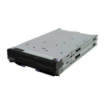
Page 139: System Components
Figure 4-1 IBM System x3690 X5 Figure 4-1 shows the x3690 X5 server with 16 hot-swap 2.5-inch SAS disk drives installed. The x3690 server has these physical specifications: Height: 86 mm (3.5 inches, 2U) Depth: 698 mm (27.4 inches) Width: 429 mm (16.8 inches) Maximum weight: 31.3 kg (69 lb) when fully configured... - Page 140 A further 16 DIMMs are on the memory mezzanine) system planar underneath (not visible). Bays for four Five hot-swap fans Drive bays hot-swap power (accessible through supplies door in top cover) Figure 4-4 The x3690 X5 internals IBM eX5 Implementation Guide...
-
Page 141: Ibm Max5 Memory Expansion Unit
If the top cover is removed, the server powers off immediately. 4.1.2 IBM MAX5 memory expansion unit The IBM MAX5 for System x (MAX5) memory expansion unit has 32 DDR3 DIMM sockets, one or two 675-watt power supplies, and five 40 mm hot-swap speed-controlled fans. It provides added memory and multinode scaling support for host servers. - Page 142 Figure 4-6 MAX5 connectors and LEDs Figure 4-7 on page 123 shows the internals of the MAX5, including the IBM EXA chip that acts as the interface to the QPI links from the x3690 X5. IBM eX5 Implementation Guide...
-
Page 143: Target Workloads
The result can lead to client savings on hardware and also on software licensing. Database The larger memory capacity of the x3690 X5 also offers leadership database performance. The x3690 X5 features the IBM eXFlash internal storage using SSDs to maximize the number of IOPS. Chapter 4. IBM System x3690 X5... -
Page 144: Models
Up to 64 DIMM sockets: Each server has 16 DIMM sockets standard or 32 sockets with the addition of the internal memory tray (mezzanine). With the addition of the MAX5 memory expansion unit, 64 DIMM sockets total are available. b. Emulex 10Gb Ethernet Adapter IBM eX5 Implementation Guide... - Page 145 Up to 64 DIMM sockets: Each server has 16 DIMM sockets standard or 32 sockets with the addition of the internal memory tray (mezzanine). With the addition of the MAX5 memory expansion unit, 64 DIMM sockets total are available. b. Emulex 10Gb Ethernet Adapter. Chapter 4. IBM System x3690 X5...
-
Page 146: System Architecture
MAX5. The EXA ports and other two QPI are unused in this configuration. External connectors Memory Memory buffer buffer IBM EXA Memory Memory chip buffer buffer Memory Memory buffer buffer links links Memory Memory buffer buffer Figure 4-9 MAX5 block diagram IBM eX5 Implementation Guide... -
Page 147: Max5
IBM MAX5 to x3690 X5 Cable Kit (two cables) The eX5 chip set in the MAX5 is an IBM unique design that attaches to the QPI links as a node controller, giving it direct access to all CPU bus transactions. It increases the number of DIMMs supported in a system by a total of 32, and also adds another 16 channels of memory bandwidth, boosting overall throughput. -
Page 148: Scalability
For memory configuration information, see 4.8.3, “MAX5 memory” on page 136. For a description of the power and fans, see 4.12, “Power supplies” on page 173. 4.6 Scalability In this section, we describe how the x3690 X5 can be expanded to increase the number of memory DIMMs. IBM eX5 Implementation Guide... - Page 149 Rack rear Figure 4-12 Connecting the MAX5 to a single-node x3690 X5 Connecting the MAX5 to a single-node x3690 X5 requires one IBM MAX5 to x3690 X5 Cable Kit, which consists of two QPI cables. See Table 4-4. Table 4-4 Ordering information for the IBM MAX5 to x3690 X5 Cable Kit...
-
Page 150: Processor Options
See 2.2.3, “Turbo Boost Technology” on page 18 for more information. With the exception of the X7542, all CPUs that are listed support Intel Hyper-Threading Technology. Hyper-Threading Technology (HT) is an Intel technology that is used to improve IBM eX5 Implementation Guide... -
Page 151: Memory
Tip: The memory mezzanine is referred to in the announcement letter as the memory expansion card memory tray . It is referred to as the , in the Installation and User’s Guide - IBM System x3690 X5. Chapter 4. IBM System x3690 X5... - Page 152 The memory mezzanine is an optional component and orderable as listed in Table 4-6. Table 4-6 x3690 X5 memory mezzanine option part number Option Feature code Description 60Y0323 9278 IBM x3690 X5 16-DIMM Internal Memory Expansion Figure 4-13 shows the memory mezzanine and DIMMs. Memory mezzanine Memory mezzanine Installing the...
-
Page 153: Memory Dimm Options
4.8.2 x3690 X5 memory population order Memory DIMM installation is key to maximizing system performance. In this section, we specify how to install DIMMs. Figure 4-14 on page 134 shows the slot numbering for DIMM installation. Chapter 4. IBM System x3690 X5... - Page 154 When the memory mezzanine is not installed, install the DIMMs in the order that is listed in Table 4-8 on page 135. Only certain DIMM combinations result in Hemisphere Mode being enabled. Hemisphere Mode improves memory performance, as described in 2.3.5, “Hemisphere Mode” on page 26. IBM eX5 Implementation Guide...
- Page 155 Install the memory in the order that is listed in Table 4-9 on page 136. You are required to install a minimum of four DIMMs. Figure 4-15 on page 136 shows the DIMM numbering on the memory mezzanine. Chapter 4. IBM System x3690 X5...
-
Page 156: Max5 Memory
For a full list of supported memory configurations, see the IBM System x3690 X5 Installation and User Guide or the IBM System x3690 X5 Problem Determination and Service Guide. You can obtain both of these documents at the following website: http://www.ibm.com/support... - Page 157 SMI link speed, which in turn dictates the memory speed. 4.7, “Processor options” on page 130, summarizes the memory speeds for all of the models of Intel Xeon 7500 series CPUs. Chapter 4. IBM System x3690 X5...
- Page 158 The colors in Table 4-11 match the colors in Figure 4-16. Table 4-11 DIMM installation sequence in the MAX5 DIMM pair DIMM slot 28 and 29 9 and 16 1 and 8 IBM eX5 Implementation Guide...
-
Page 159: Memory Balance
Looking at Figure 4-17 on page 140 as an example, Processor 0 has DIMMs populated, but no DIMMs are populated that are connected to Processor 1. In this case, Processor 0 has access to low latency local memory and high memory bandwidth. However, Processor 1 has Chapter 4. IBM System x3690 X5... -
Page 160: Mixing Dimms And The Performance Effect
Hemisphere Mode is maintained. Configuration D: Four DIMMs of one capacity (4 GB) are populated across four memory channels, and four DIMMs of another capacity (2 GB) are populated on the other four IBM eX5 Implementation Guide... -
Page 161: Memory Mirroring
DIMM installation for 3690 X5 Table 4-12 lists the DIMM installation sequence for memory-mirroring mode when one or two processors are installed in the server and no memory mezzanine tray is installed in the server. Chapter 4. IBM System x3690 X5... - Page 162 IBM eX5 Implementation Guide...
-
Page 163: Memory Sparing
DIMM that we are sparing. The size of the two unused ranks for sparing is subtracted from the usable capacity presented to the operating system. Rank sparing is applied on all memory cards in the system. Chapter 4. IBM System x3690 X5... -
Page 164: Effect On Performance Of Using Mirroring Or Sparing
DIMMs. Figure 4-19 shows the peak system-level memory throughput for various memory modes measured using an IBM-internal memory load generation tool. As shown, there is a 50% decrease in peak memory throughput when going from a normal (non-mirrored) configuration to a mirrored memory configuration. -
Page 165: Storage
60Y0369 for a 4x backplane). The database model 7148-3Dx has two IBM eXFlash 8x 1.8-inch HS SAS SSD backplanes as standard. See 4.3, “Models” on page 124 for details. The standard backplanes are installed in the leftmost sections. - Page 166 Drives supported SAS cables number code included 60Y0339 9287 IBM 4x 2.5” HS SAS HDD Backplane Four 2.5” SAS drives 1 short, 1 long 60Y0381 1790 IBM 8x 2.5” HS SAS HDD Backplane Eight 2.5” SAS drives 2 short, 2 long a.
- Page 167 Table 4-19 The 2.5-inch disk drive options for the x3690 X5 Part number Feature code Description Backplane used 42D0672 5522 IBM 73GB 15K 6Gbps SAS 2.5-inch SFF Slim-HS HDD 4x/8x SAS HDD 42D0632 5537 IBM 146GB 10K 6Gbps SAS 2.5-inch SFF Slim-HS HDD 4x/8x SAS HDD 42D0677 5536 IBM 146GB 15K 6Gbps SAS 2.5-inch SFF Slim-HS HDD...
- Page 168 Single 500 GB SATA drive The x3690 X5 optionally supports the IBM x3690 X5 Single SATA HDD Bay, which contains a single 500 GB SATA drive with mounting hardware. You can use the single SATA drive as a boot drive when the system is populated with eXFlash SSDs.
-
Page 169: Ibm Exflash And Ssd Disk Support
SSD. 4.9.2 IBM eXFlash and SSD disk support IBM eXFlash is the name of the feature of the x3690 X5 that offers high-performance 1.8-inch SSDs via optimized eXFlash SSD backplanes and SSD controllers. - Page 170 SSDs to 24. The IBM eXFlash 8x 1.8-inch HS SAS SSD Backplane, part number 60Y0360, supports eight 1.8-inch High IOPS SSDs, as shown in Table 4-23. The eight drive bays require the same physical space as four SAS hard disk bays.
- Page 171 Table 4-25 Controllers supported with the eXFlash SSD backplane option Part number Feature code Description 46M0914 3876 IBM 6Gb SSD Host Bus Adapter (No RAID support) 46M0829 0093 ServeRAID M5015 SAS/SATA Controller 46M0916 3877 ServeRAID M5014 SAS/SATA Controller 46M0969 3889...
-
Page 172: Sas And Ssd Controller Summary
Ability to enable SED support for encryption-equipped devices. Convenient upgrade with easy-to-use pluggable key. For more information, see the IBM Redbooks at-a-glance guide ServeRAID M5000 Series Performance Accelerator Key for IBM System x, which is available at this website: http://www.ibm.com/redbooks/abstracts/tips0799.html 4.9.3 SAS and SSD controller summary In this section, we provide details for the features of each controller card and what they offer. - Page 173 The IBM 6Gb SSD Host Bus Adapter is currently not available as a separately orderable option. Use the feature code to add the adapter to a customized order, using the CTO process. Part number 46M0914 is the L1 manufacturing part number. Part number 46M0983 is the pseudo option number, which is also used in manufacturing.
- Page 174 Advanced Feature Key but also includes performance enhancements to enable SSD support in a mixed HDD environment. For more information, see ServeRAID M5015 and M5014 SAS/SATA Controllers for IBM System x, TIPS0738, which is available at the following website: http://www.redbooks.ibm.com/abstracts/tips0738.html?Open...
-
Page 175: Battery Backup Placement
Important: Two variants of the 6 Gb Host Bus Adapter exist. The SSD variant has no external port and is part number 46M0914. Do not confuse it with the IBM 6 Gb SAS HBA, part number 46M0907, which is not supported for use with eXFlash. - Page 176 Figure 4-26 shows how the battery trays are installed in the memory mezzanine. Each battery tray can hold two batteries. RAID battery trays Memory mezzanine Figure 4-26 RAID battery trays on the memory mezzanine IBM eX5 Implementation Guide...
-
Page 177: Serveraid Expansion Adapter
4.9.5 ServeRAID Expansion Adapter The ServeRAID Expansion Adapter, which is also known as the IBM x3690 X5 RAID Expansion Adapter or IBM 4x4 Drive Backplane ServeRAID Expansion adapter, is a SAS expander. It allows you to create RAID arrays of up to 16 drives and across up to four backplanes. -
Page 178: Drive Combinations
Figure 4-28 shows a four-drive configuration that uses one 4x HDD backplane. This configuration uses one SAS cable. Figure 4-28 x3690 with one IBM 4x 2.5-inch HS SAS HDD backplane Configurations with eight drives Figure 4-29 shows two 4x HDD backplanes in use. This configuration requires two SAS cables. - Page 179 Figure 4-30 x3690 X5 with one IBM 8x 2.5-inch HS SAS HDD backplane Figure 4-31 illustrates the IBM eXFlash 8x SAS SSD backplane, which requires two SAS cables. With the eXFlash, eight drives can be used in the same space as four 2.5-inch drives.
- Page 180 Figure 4-35 and Figure 4-36 both show the full sixteen 2.5-inch drive configuration. Both configurations require four SAS cables. Figure 4-35 x3690 with four IBM 4x 2.5-inch HS SAS HDD backplanes Figure 4-36 x3690 with two IBM 8x 2.5-inch HS SAS HDD backplanes Figure 4-37 illustrates another 16-drive configuration with one 8x and two 4x backplanes.
- Page 181 Figure 4-39 shows two 8x eXFlash backplanes. Using these two backplanes requires four SAS cables. Figure 4-39 also shows the use of a single SATA drive. Figure 4-39 x3690 X5 with two IBM eXFlash 8x 1.8-inch SSD backplanes and a single SATA drive Configurations with 20 drives Figure 4-40 shows a full complement of drives using three 4x backplanes and one 8x eXFlash backplane.
-
Page 182: External Sas Storage
4x backplanes. Six SAS cables are required. Figure 4-42 x3690 X5 with two 4x 2.5-inch backplanes and two IBM eXFlash 8x 1.8” SSD backplanes Figure 4-43 shows the maximum number of 8x eXFlash backplanes supported in an x3690 X5. -
Page 183: Optical Drives
– LSI SafeStore: Support for self-encrypting drive services, such as instant secure erase and local key management (which requires the use of self-encrypting drives). For more information, see ServeRAID M5025 SAS/SATA Controller for IBM System x, TIPS0739, which is available at the following website: http://www.redbooks.ibm.com/abstracts/tips0739.html?Open... -
Page 184: Pcie Slots
Figure 4-45 on page 164 shows the locations of the two riser cards in the server. Adapters PCIe riser 1 with slots 1 and 2 PCIe riser 2 with slots 3, 4 and 5 PCI slots on planar Figure 4-45 Location of the PCIe riser cards in the server IBM eX5 Implementation Guide... -
Page 185: Riser 1
9285 IBM System x3690 X5 PCI-Express (2x8) Riser Card 60Y0331 9282 IBM System x3690 X5 PCI-Express (1x16) Riser Card - 3/4 length 60Y0337 9283 IBM System x3690 X5 PCI-Express (1x16) Riser Card - full length a. The 2x8 riser card is standard in all x3690 X5 models, including 7148-ARx. -
Page 186: Emulex 10Gb Ethernet Adapter
(for example, under warranty), order the CRU number, as shown in Table 4-33. The table also shows the regular Emulex 10Gb Virtual Fabric Adapter (VFA) for IBM System x option, which differs only in the connector type (standard x8) and the color of the circuit board (green). - Page 187 49Y4250 5749 Not applicable General details about this card are in Emulex 10Gb Virtual Fabric Adapter for IBM System x, TIPS0762, which is available at the following website: http://www.redbooks.ibm.com/abstracts/tips0762.html Important: Although these cards are functionally identical, the availability of iSCSI and Fibre Channel over Ethernet (FCoE) upgrades for one card does not automatically mean availability for both cards.
-
Page 188: I/O Adapters
Storage 42D0486 3580 Emulex 8Gb FC Single-port HBA 42D0495 3581 Emulex 8Gb FC Dual-port HBA 42D0502 3578 QLogic 8Gb FC Single-port HBA 42D0511 3579 QLogic 8Gb FC Dual-port HBA 46M6051 3589 Brocade 8Gb FC Single-port HBA IBM eX5 Implementation Guide... -
Page 189: Standard Features
System event log Automatic CPU disable on failure restart in the two-CPU configuration, when one CPU signals an internal error Intelligent Platform Management Interface Specification (IPMI) V2.0 and Intelligent Platform Management Bus (IPMB) support Chapter 4. IBM System x3690 X5... -
Page 190: Ethernet Subsystem
Light path diagnostics is a system of LEDs used to indicate failed components or system errors. When an error occurs, LEDs are lit on the light path diagnostics panel. Figure 4-47 on page 171 shows the location of the light path diagnostics panel on the x3690 X5. IBM eX5 Implementation Guide... -
Page 191: Cooling
Power supply failures PCI errors You can obtain the full details about the functions and operation of light path diagnostics in this system in the Installation and User’s Guide - IBM System x3690 X5 at the following website: http://www.ibm.com/support/docview.wss?uid=psg1MIGR-5085206 4.11.6 Cooling... - Page 192 Figure 4-48 x3690 X5 fans Figure 4-49 shows the top of the server and the hot-swap fan access panel. Figure 4-49 Hot-swap fan access panel The following conditions affect system fan-speed adjustments: Inlet Ambient temperature CPU temperatures IBM eX5 Implementation Guide...
-
Page 193: Power Supplies
See 4.3, “Models” on page 124 for details. One power supply is sufficient when the total power budget is less than 675W. Use the IBM System x and BladeCenter Power Configurator to determine the power requirements of your configuration: http://www.ibm.com/systems/bladecenter/resources/powerconfig.html... -
Page 194: Max5 Power Subsystem
Most standard models of MAX5 have one power supply installed in power supply bay 1, as listed in 4.3, “Models” on page 124. For redundancy, install the second power supply, as listed in Table 4-38. Table 4-38 Ordering information for the IBM MAX5 for System x Part number Feature code... -
Page 195: Supported Operating Systems
Figure 4-50 Low profile x8 riser card with hypervisor flash USB connector The IBM USB Memory Key for virtualization is included in the virtualization-optimized models that are listed in 4.3, “Models” on page 124, but it can be added to any x3690 X5 system. -
Page 196: Rack Mounting
Table 4-41 Cable management arms Part Feature Name Use with number code rail kit 69Y2347 6473 IBM System x3690 X5 Cable Management Arm for Ball Bearing Slides 69Y2345 69Y2344 6474 IBM System x3690 X5 2U Cable Management Arm 69Y4403 69Y4390 6458 Friction CMA 69Y4389... -
Page 197: Chapter 5. Ibm Bladecenter Hx5
IBM BladeCenter HX5 Chapter 5. The IBM BladeCenter HX5 blade server showcases the eX5 architecture and technology in a blade form factor. This chapter introduces the server and describes its features and options. This chapter contains the following topics: 5.1, “Introduction” on page 178 5.2, “Target workloads”... -
Page 198: Introduction
5.1 Introduction The IBM BladeCenter HX5 supports up to two processors using Intel Xeon 6500 (Nehalem EX) 4-core, 6-core, or 8-core processors or four processors using the Intel Xeon 7500 Nehalem EX 4-core, 6-core, or 8-core processors. The HX5 supports up to 40 dual inline memory modules (DIMMs) with the addition of the MAX5 memory expansion blade when using Xeon 7500 Nehalem EX. - Page 199 Figure 5-2 Layout of HX5 (showing a 2-node 4-socket configuration) The MAX5 memory expansion blade, which is shown in Figure 5-3 on page 180, is a device with the same dimensions as the HX5. When the MAX5 is attached to the HX5, the combined Chapter 5. IBM BladeCenter HX5...
-
Page 200: Comparison To The Hs22 And Hs22V
12 MB, 18 MB, or 24 MB (shared between cores) Memory Speed Up to 1333 MHz Up to 1333 MHz 978 or 800 MHz HX5: Up to 978 MHz (scalable memory MAX5: Up to 1066MHz interconnects (SMI) (SMI link-speed link-speed dependent) dependent) IBM eX5 Implementation Guide... -
Page 201: Target Workloads
The multicore processors, large memory capacity, and I/O options make the HX5 proficient at taking on database workloads that are being transferred to the blade form factor. Chapter 5. IBM BladeCenter HX5... -
Page 202: Chassis Support
HX5 1-socket + MAX5 (60 mm) 130W a. IBM BladeCenter H 2980W AC Power Modules, 68Y6601 (standard in 4Tx, optional with all other BC-H chassis models) b. IBM BladeCenter H Enhanced Cooling Modules, 68Y6650 (standard in 4Tx, optional with all other BC-H chassis models) c. -
Page 203: Models
This column lists worldwide, generally available variant (GAV) model numbers. They are not orderable as listed and must be modified by country. The US GAV model numbers use the following nomenclature: xxU. For example, the US orderable part number for 7870-A2x is 7870-A2U. See the product-specific official IBM announcement letter for other country-specific GAV model numbers. -
Page 204: System Architecture
One PCI Express x16 CFFh I/O expansion connector One PCI Express x16 CFFh-style connector for use with the SSD Expansion Card and one or two solid-state drives One CIOv I/O expansion connector Scalability connector One internal USB port for embedded virtualization IBM eX5 Implementation Guide... -
Page 205: Speed Burst Card
To increase performance in a 2-socket HX5 server (that is, with two processors installed), install the IBM HX5 1-Node Speed Burst Card. The 1-Node Speed Burst Card takes the QPI links that typically are used for scaling two HX5 2-socket blades and routes them back to the processors on the same blade. -
Page 206: Ibm Max5 For Bladecenter
Figure 5-6 Installing the Speed Burst Card 5.7 IBM MAX5 for BladeCenter IBM MAX5 for BladeCenter, which is shown in Figure 5-3 on page 180, is a memory expansion blade that attaches to HX5 2-socket blade servers. It has the following system... - Page 207 Attachment to a single HX5 using the IBM HX5 MAX5 1-node Scalability kit, part number 59Y5877, as described in 5.8.3, “HX5 with MAX5” on page 190 Communication with the processors on the HX5 using high-speed QPI links MAX5 is standard with certain models, as listed in 5.4, “Models” on page 183. For other models, MAX5 is available as an option, as listed in Table 5-8.
-
Page 208: Scalability
The two servers are connected using a 2-node scalability card, as shown in Figure 5-8 on page 189. The scalability card is immediately adjacent to the processors and provides a direct connection between the processors in the two nodes. IBM eX5 Implementation Guide... - Page 209 Feature code Description 46M6975 1737 IBM HX5 2-Node Scalability Kit The IBM HX5 2-Node Scalability Kit contains the 2-node scalability card, plus the necessary hardware to physically attach the two HX5 servers to each other. Chapter 5. IBM BladeCenter HX5...
-
Page 210: Hx5 With Max5
“Creating an HX5 scalable complex” on page 402 for more information. 5.8.3 HX5 with MAX5 In the HX5 and MAX5 configuration, the HX5 and MAX5 units connect through a 1-node MAX5 scalability card, which provides QPI scaling. See Figure 5-10 on page 191. IBM eX5 Implementation Guide... - Page 211 Figure 5-10 Single-node HX5 + MAX5 The card that is used to connect the MAX5 to the HX5 is the IBM HX5 MAX5 1-Node Scalability Kit, which is extremely similar in physical appearance to the 2-Node Scalability Kit that was shown in Figure 5-8 on page 189. Table 5-10 lists the ordering information.
-
Page 212: Processor Options
800 MHz Xeon E7530 6C 1.86 GHz Yes +2 12 MB 105 W 5.86 GT/s 978 MHz 978 MHz Xeon E7540 6C 2.0 GHz Yes +2 18 MB 105 W 6.4 GT/s 978 MHz 1066 MHz IBM eX5 Implementation Guide... - Page 213 If a MAX5 memory expansion blade is installed, the memory in the MAX5 can operate as high as 1066 MHz, depending on the DIMMs installed. The MAX5 memory speed is independent of the HX5 memory speed. For more information about calculating memory speed, see 2.3.1, “Memory speed” on page 22. Chapter 5. IBM BladeCenter HX5...
-
Page 214: Memory
Two GB DIMM option: The 2 GB DIMM option that is listed in Table 5-13 is not supported in the MAX5, because the MAX5 does not support mixing DIMMs with various DRAM technologies, such as 1 Gb versus 2 Gb. IBM eX5 Implementation Guide... - Page 215 The MAX5 memory expansion blade has 24 memory DIMM sockets, as shown in Figure 5-14 on page 196. The MAX5, which must be connected to an HX5 system (only the 1-node HX5 supports the MAX5), has one memory controller and six SMI-connected memory buffers. Chapter 5. IBM BladeCenter HX5...
-
Page 216: Dimm Population Order
This sequence spreads the DIMMs across as many memory buffers as possible. Installation methods: These configurations use the most optimized method for performance. For optional installation methods, see the BladeCenter HX5 Problem Determination and Service Guide at the following website: http://ibm.com/support/entry/portal/docdisplay?lndocid=MIGR-5084529 IBM eX5 Implementation Guide... - Page 217 Every memory bus operates at this speed. Table 5-15 NUMA-compliant DIMM installation for a 2-node HX5 Processor 1 Processor 2 Buffer Buffer Buffer Buffer Buffer Buffer Buffer Buffer Chapter 5. IBM BladeCenter HX5...
- Page 218 16 15 IBM EXA chip 20 19 Memory Memory buffer buffer 18 17 23 24 Memory Memory links buffer buffer 21 22 Power domain C Figure 5-15 Power domains in the MAX5 memory expansion blade IBM eX5 Implementation Guide...
-
Page 219: Memory Balance
For the best memory performance, install the DIMMs by spreading them among all six memory buffers and all three power domains. Table 5-16 shows the installation order. Table 5-16 DIMM installation for the MAX5 for IBM BladeCenter Power domain A Domain C (½) -
Page 220: Memory Mirroring
This section contains DIMM placements for each solution. Important: If using memory mirroring, all DIMMs must be identical in size and rank. DIMM placement: HX5 Table 5-17 on page 201 lists the DIMM installation sequence for memory-mirroring mode when one processor is installed. IBM eX5 Implementation Guide... - Page 221 DIMM placement: MAX5 Table 5-19 lists the DIMM installation sequence in the MAX5 for memory-mirroring mode. Only power domains A and B are populated. Table 5-19 DIMM installation for the MAX5 memory mirroring for IBM BladeCenter Power domain A Domain C (½) Power domain B Domain C (½)
-
Page 222: Memory Sparing
As shown in Table 5-13 on page 194, the 8 GB DIMM, part number 49Y1554, uses x4 DRAM technology. RBS is automatically enabled in the MAX5 memory port, if all DIMMs installed to that memory port are x4 DIMMs. IBM eX5 Implementation Guide... -
Page 223: Storage
1.8-inch solid-state drives (SSDs). If two SSDs are installed, the HX5 supports RAID-0 or RAID-1 capability. Installation of the SSDs in the HX5 requires the SSD Expansion Card for IBM BladeCenter HX5. Only one SSD Expansion Card is needed for either one or two SSDs. Table 5-22 lists the ordering details. -
Page 224: Solid-State Drives (Ssds)
SCSI (SAS) drive, approximately 0.5 W (SSD) versus 11 W (SAS). Target applications for SSDs include video surveillance, transaction-based database (DB), and other applications that have high performance but moderate space requirements. Table 5-23 on page 205 lists the supported SSDs. IBM eX5 Implementation Guide... -
Page 225: Lsi Configuration Utility
43W7734 5314 IBM 50GB SATA 1.8-inch NHS SSD For more information about SSD drives and their advantages, see 2.8.1, “IBM eXFlash price-performance” on page 49. 5.11.2 LSI configuration utility Figure 5-20 shows the LSI SAS Configuration Utility window running on a 2-node HX5 with one controller in each node. - Page 226 The stripe size is 64 Kb and cannot be altered. We provide the instructions to create an array in 8.4, “Local storage considerations and array setup” on page 385. IBM eX5 Implementation Guide...
-
Page 227: Determining Which Ssd Raid Configuration To Choose
We ran these tests on an HX5 2-node system running four 2 GHz Intel Xeon 7500 series 6-core processors and 16 GB of memory. The SSDs were IBM 50 GB SATA 1.8-inch NHS SSDs. Results might vary depending on the size and type of installed drives. -
Page 228: Bladecenter Pci Express Gen 2 Expansion Blade
Figure 5-24 Connecting SAS Connectivity Card and external SAS solution 5.12 BladeCenter PCI Express Gen 2 Expansion Blade The IBM BladeCenter PCI Express Gen 2 Expansion Blade provides the capability to attach selected PCI Express cards to the HX5. This capability is ideal for many applications that require special telecommunications network interfaces or hardware acceleration using a PCI Express card. -
Page 229: I/O Expansion Cards
BladeCenter S, H, or HT chassis. For details about the supported PCI Express adapter cards, see the IBM Redbooks at-a-glance guide, IBM BladeCenter PCI Express Gen 2 Expansion Blade, TIPS0783, which is available at this website: http://www.ibm.com/redbooks/abstracts/tips0783.html... -
Page 230: Cffh
44W4475 5477 Ethernet Expansion Card (CIOv) See the IBM ServerProven compatibility website for the latest information about the expansion cards that are supported by the HX5: http://ibm.com/servers/eserver/serverproven/compat/us/ CIOv expansion cards are installed in the CIOv slot in the HX5 2-socket, as shown in Figure 5-25. - Page 231 0056 2-port 40Gb InfiniBand Expansion Card (CFFh) a. IBM System x has withdrawn this card from marketing. See the IBM ServerProven compatibility website for the latest information about the expansion cards that are supported by the HX5: http://ibm.com/servers/eserver/serverproven/compat/us/ CFFh expansion cards are installed in the CFFh slot in the HX5, as shown in Figure 5-26.
-
Page 232: Standard Onboard Features
Using all of the features of UEFI requires an UEFI-aware operating system and adapters. UEFI is fully backward-compatible with BIOS. For more information about UEFI, see the IBM white paper, Introducing UEFI-Compliant Firmware on IBM System x and BladeCenter Servers, which is available at the following website: http://www.ibm.com/support/docview.wss?uid=psg1MIGR-5083207 For the UEFI menu setup, see 8.5, “UEFI settings”... -
Page 233: Integrated Management Module (Imm)
Remote Supervisor Adapter (RSA) in System x servers, and also remote control and remote media. For more information about the IMM, see the IBM white paper, Transitioning to UEFI and IMM, which is available at the following website: http://www.ibm.com/support/docview.wss?uid=psg1MIGR-5079769... -
Page 234: Integrated Virtualization
5.15 Integrated virtualization The HX5 offers an IBM 2 GB USB flash drive option that is preloaded with either VMware ESXi 4.0 Update 1 or VMware ESXi 4.1: ESXi 4.0 is for 1-node HX5 configurations only. ESXi 4.1 is required for configurations with the MAX5 memory expansion blade or for 2-node HX5 configurations. -
Page 235: Operating System Support
Red Hat Enterprise Linux 5 Server with Xen x64 Edition Red Hat Enterprise Linux 6 Server x64 Edition SUSE Linux Enterprise Server 10 for AMD64/EM64T SUSE Linux Enterprise Server 10 with Xen for AMD64/EM64T SUSE Linux Enterprise Server 11 for AMD64/EM64T Chapter 5. IBM BladeCenter HX5... - Page 236 Key information regarding VMware ESX: ESXi 4.0 support is single-node HX5 only. ESX 4.0 supports single-node and 2-node HX5. ESXi 4.1 and ESX 4.1 are required for MAX5 support. See the ServerProven website for the most recent information: http://ibm.com/systems/info/x86servers/serverproven/compat/us/nos/ematrix.shtml IBM eX5 Implementation Guide...
-
Page 237: Part 2. Implementing Scalability
2-node configurations of the x3850 X5 and HX5. This part consists of the following chapters: Chapter 6, “IBM System x3850 X5 and x3950 X5” on page 219 Chapter 7, “IBM System x3690 X5” on page 301 Chapter 8, “IBM BladeCenter HX5”... - Page 238 IBM eX5 Implementation Guide...
-
Page 239: Chapter 6. Ibm System X3850 X5 And X3950 X5
IBM System x3850 X5 and x3950 X5 Chapter 6. The System x3850 X5 and x3950 X5 are enterprise-class Intel processor-based servers for mission-critical applications. Scaling two of these servers together and virtualizing the resources allow this server to replace an entire rack of conventional servers. -
Page 240: Before You Apply Power For The First Time After Shipping
For all you know, it might have been parked next to a large magnet or electric motor and everything in the server that stores information magnetically, including CMOS memory, has been altered. IBM does not indicate on the shipping carton that magnetic material is enclosed because the information is readily recoverable. -
Page 241: Verify That The Server Completes Post Before Adding Options
As a matter of standard manufacturing, the producing vendor might alter the method of manufacturing the processor, which results in separate stepping levels, but does not affect the overall functionality of the processor in its ability to communicate with other processors in the Chapter 6. IBM System x3850 X5 and x3950 X5... -
Page 242: Minimum Processors Required
DIMMs on memory card 1. Processing threads assigned to processor 4 always have a significant drop in performance for memory-intensive tasks. This configuration is not an operational configuration for operating systems, such as VMware. IBM eX5 Implementation Guide... - Page 243 QPI slot 3 and 4 has failed or is not installed. Failure of a QPI wrap card will be represented in the hardware event log as a loss of a redundant QPI lane for two of the processors. Chapter 6. IBM System x3850 X5 and x3950 X5...
-
Page 244: Processor Installation Order
Redundant QPI link failures between two processors, between a processor and the I/O hub, or between a processor and the MAX5 Figure 6-2 on page 225 shows the processor tool that is used to install a processor in this system safely or remove a processor from this system. IBM eX5 Implementation Guide... -
Page 245: Local Memory Configuration
Section 3.8, “Memory” on page 76 covers all of the various technical considerations regarding memory configuration for the System x3850 X5. You have a great deal of flexibility when configuring the memory for this server. However, as a result, you might configure a less than optimal memory environment. -
Page 246: Testing The Memory Dimms
The following reasons describe why memory might not be functional: Wrong DIMM for the type of server that you have. Ensure that only IBM-approved DIMMs are installed in your server. The DIMM is not fully installed. Ensure that the DIMM clips are in the locked position to prevent the DIMM from pulling out of its slot. - Page 247 1. During POST, at the IBM System x splash panel, press F2-Diagnostics, as shown in Figure 6-3. Figure 6-3 How to access diagnostics in POST 2.
- Page 248 Figure 6-5. Figure 6-5 Quick Memory Test progress panel You can terminate the diagnostics at any point by pressing Esc. IBM eX5 Implementation Guide...
-
Page 249: Memory Fault Tolerance
1. Boot the server into F1-Setup by pressing F1. 2. From the System Configuration panel, select System Settings Memory. See Figure 6-6. Figure 6-6 The memory configuration panel in F1-Setup Chapter 6. IBM System x3850 X5 and x3950 X5... -
Page 250: Attaching The Max5 Memory Expansion Unit
6.4 Attaching the MAX5 memory expansion unit On top of the 1 terabyte (TB) of memory that you can configure on System x3850 X5, you can also configure an additional half of a TB of memory in the MAX5 memory expansion unit and attach the MAX5 to the server to increase the overall memory access performance and capacity. -
Page 251: Installing In A Rack
MAX5 to be mounted to the x3850 through a series of brackets and rail kits. For cabling instructions, see the product publication IBM eX5 MAX5 to x3850 X5 and x3950 X5 QPI Cable Kit and IBM eX5 MAX5 2-Node EXA Scalability Kit Installation Instructions, which is available at this website: http://ibm.com/support/entry/portal/docdisplay?lndocid=MIGR-5084861... - Page 252 You must install QPI cables for each of the processors installed to ensure full memory access to the MAX5. Table 6-3 on page 233 describes the QPI port on the back of the server with the corresponding processor socket in the server. IBM eX5 Implementation Guide...
-
Page 253: Accessing The Dimms In The Max5
1. Remove ac power from all of the server’s power supplies and from the two MAX5 power supplies. Because the QPI cables are already held in alignment by the memory expansion Chapter 6. IBM System x3850 X5 and x3950 X5... - Page 254 FPGA components exist on both the server and the MAX5. Removing the memory board with the ac power still active damages the FPGA components of both the server and the MAX5. For memory population order, see 4.9, “Storage” on page 145. IBM eX5 Implementation Guide...
-
Page 255: Forming A 2-Node X3850 X5 Complex
When all of the prerequisites of scaling to X3850 X5 servers have been met and the servers are scaled, you can apply all of the updates that are provided by IBM for the stand-alone chassis to the scale chassis as if it were a single unit. The only exception to this rule is the replacement of either the I/O shuttle or the processor board on either node. -
Page 256: Processor Requirements
Figure 6-12. It is a good idea to keep a set of these plastic boots if you want to remove the QPI cables for the movement of equipment from rack to rack or for servicing the unit. Figure 6-12 Reusable QPI cable connector protective boot IBM eX5 Implementation Guide... - Page 257 Neither server can power on if the cables are not consistent in their orientation. Figure 6-14 shows how the cable ends are labeled. Figure 6-14 QPI cable end labels: J1 and J2 attach to the primary node Chapter 6. IBM System x3850 X5 and x3950 X5...
-
Page 258: Pcie Adapters And Riser Card Options
This section describes considerations to remember for determining how to use your PCIe slots, depending on the types of PCIe riser cards that you have installed. The x3850 X5 is an enterprise server that is designed to function in a high availability cluster or powerful IBM eX5 Implementation Guide... -
Page 259: Generation 2 And Generation 1 Pcie Adapters
(GT/s). You can also adjust the QPI link speed to conserve power by booting into F1-Setup, selecting System Settings Operating Modes, and setting QPI Link Frequency to values other than the default Max Performance, as shown in Figure 6-15 on page 240. Chapter 6. IBM System x3850 X5 and x3950 X5... - Page 260 Figure 6-15 QPI Link Frequency setting PCie adapter compatibility IBM ServerProven tests IBM and non-IBM adapters that have been proven to function correctly in the System x3850 X5 server. See the following page for specifics: http://ibm.com/systems/info/x86servers/serverproven/compat/us/xseries/7148.html Backward compatibility of Gen2 PCie slots to Gen1 adapters All Gen2 PCIe slots are backward-compatible to Gen1 adapters;...
- Page 261 4 GB. If you have previously disabled Thunking, you can re-enable it by using F1-Setup and selecting System Settings Legacy Support. Figure 6-17 on page 242 shows the Legacy Support panel. Chapter 6. IBM System x3850 X5 and x3950 X5...
- Page 262 Legacy Only when it is displayed in the list of options. Figure 6-18 on page 243 shows where Legacy Only is located in the list of available boot options. If Legacy Only is not listed, it has already been added to the Boot Manager. IBM eX5 Implementation Guide...
- Page 263 Enter and then selecting the item to move by using the arrow keys. When Legacy Only is selected, use the plus (+) key to move it up the panel. Figure 6-19 Change Boot Order panel Chapter 6. IBM System x3850 X5 and x3950 X5...
-
Page 264: Pcie Adapters: Slot Selection
QPI link to the I/O hub is capable of a maximum throughput of 26 GBs, depending on the processors installed on the server. With only one processor installed, the maximum combined bandwidth of all the PCIe lanes is reduced to the maximum bandwidth of a single IBM eX5 Implementation Guide... -
Page 265: Cleaning Up The Boot Sequence
I/O Ports Enable / Disable Legacy Option ROM(s). Figure 6-20 on page 246 shows the available options. You need to know the specific PCIe slots that were used for each adapter, so that you will know which slot to leave enabled. Chapter 6. IBM System x3850 X5 and x3950 X5... - Page 266 PXE boot. Figure 6-21 on page 247 shows the panel that you will see to disable PXE boot on one of the two onboard network ports. IBM eX5 Implementation Guide...
- Page 267 To access individual adapter configuration panels from F1-Setup, select System Settings Adapters and UEFI Drivers and press Enter. Figure 6-22 shows the selections that are presented by this panel when accessed. Figure 6-22 Accessing adapter-specific configuration information Chapter 6. IBM System x3850 X5 and x3950 X5...
- Page 268 BIOS and firmware remain intact. Option ROM execution order Regardless of when you boot in Legacy Only mode or UEFI mode, you can control from which device you want to boot. This function is important when multiple storage adapters are IBM eX5 Implementation Guide...
-
Page 269: Power Supply Considerations
Figure 6-25 Set Option ROM Execution Order maintenance panel 6.7 Power supply considerations Most models of the System x3850 X5 ship with two power supplies that will support the entire server with redundant power regardless of the configuration. When the server loses one of the two power supplies, the server will report the following warning in the system event log: “Non-redundant: Sufficient Resources for Redundancy Degraded”... -
Page 270: Using The Integrated Management Module
Tip: If you have a server but you do not know the logon credentials, you can reset it by going to the panel that is shown in Figure 6-26, from F1-Setup, and then restore the IMM configuration to the factory defaults by selecting Reset IMM to Defaults. IBM eX5 Implementation Guide... -
Page 271: Imm Network Access
As shown in Figure 6-28, the port is located from the rear of the server on the left side of the video port. Using this port allows for easier separation of public and Chapter 6. IBM System x3850 X5 and x3950 X5... - Page 272 UEFI is not as tolerant. For this reason (maintaining secured access), the IMM must be kept on a separate management network. IBM eX5 Implementation Guide...
-
Page 273: Imm Communications Troubleshooting
You will need to refer to the system event log from within the operating system or the switch logs of the network and fibre switches to which the server is connected to resolve connectivity issues. Chapter 6. IBM System x3850 X5 and x3950 X5... - Page 274 When an actual hardware error is detected in the server, the system status is represented by a red X. The System Health Summary will provide information about the errors presently unresolved in the server, as shown in Figure 6-31 on page 255. IBM eX5 Implementation Guide...
- Page 275 Pulling out the front operator panel reveals the second tier of light path diagnostics (as shown in Figure 6-32) that indicates the hardware subsystem that is experiencing the error. Figure 6-32 Tier 2 of light path diagnostics Chapter 6. IBM System x3850 X5 and x3950 X5...
-
Page 276: Hardware Event Log
The event log can be saved to a text file to be sent to IBM support. Figure 6-34 on page 257 shows the IMM Event Log for the hard drive failure. - Page 277 For remotely managed servers, you can use the Remote Control feature of the Integrated Management Module. Figure 6-35 shows the options available for starting a remote control session. Figure 6-35 Integrated Management Module Remote Control session start-up panel Chapter 6. IBM System x3850 X5 and x3950 X5...
- Page 278 Fix this problem in the Video Viewer by selecting Tools Single Cursor, as shown in Figure 6-36. Figure 6-36 Fixing the mouse pointer in the Remote Control Video Viewer IBM eX5 Implementation Guide...
-
Page 279: Uefi Settings
UEFI is effectively the replacement for BIOS. BIOS has been around for many years but was not designed to handle the amount of hardware that can be added to a server today. New IBM System x models and BladeCenter Blades implement UEFI to take advantage of its advanced features. - Page 280 Max Performance Power Efficiency Minimal Power Scheduler Policy (pagepolicy) uEFI.SchedulerPolicy Static Trade Off Adaptive Static Read Primary Static Write Primary Adaptive Mapper Policy uEFI.MapperPolicy Open Closed Closed Patrol Scrub uEFI.PatrolScrub Enable Disable Disable uEFI.DemandScrub Enable Enable Disable IBM eX5 Implementation Guide...
-
Page 281: Settings Needed For 1-Node, 2-Node, And Max5 Configurations
MAX5 unit to the OS: Non-Pooled The default option. Non-Pooled splits the memory in the MAX5 and assigns it to each of the installed processors. Configure VMware and Microsoft OSs to use the Non-Pooled setting. Chapter 6. IBM System x3850 X5 and x3950 X5... -
Page 282: Uefi Performance Tuning
In this section, we provide general settings for the x3850 X5 that can be a good starting point for performance tuning. For more detailed information about the best settings for your specific environment and application needs, contact your IBM Business Partner or IBM representative. -
Page 283: Installing An Os
The following server OSs have USB support, which is required for the Remote Disk feature: Microsoft Windows Server 2008 Microsoft Windows Server 2003 Red Hat Linux versions 4.0 and 5.0 SUSE Linux version 10.0 Chapter 6. IBM System x3850 X5 and x3950 X5... - Page 284 3. If you want to allow other users remote control access during your session, click Start Remote Control in Multi-user Mode. Otherwise, click Start Remote Control in Single User Mode. 4. Two Java application windows open, as shown in Figure 6-39 and Figure 6-40. Figure 6-39 Video Viewer window IBM eX5 Implementation Guide...
-
Page 285: Local Usb Port
For VMware, you can use the embedded hypervisor key, which is preinstalled with ESXi. You do not need to install VMware. For more information about the embedded hypervisor key, see 2.9.1, “VMware ESXi” on page 50. Chapter 6. IBM System x3850 X5 and x3950 X5... -
Page 286: Serverguide Scripting Toolkit
ServerGuide Scripting Toolkit As described in 9.9, “IBM ServerGuide Scripting Toolkit” on page 507, you can use the ServerGuide Scripting Toolkit to customize your OS deployment. You can use the ServerGuide Scripting Toolkit for Windows, Linux, and VMware. This section contains information about deployment to allow you to begin using the Toolkit as quickly as possible. - Page 287 4. Insert the correct OS installation media or select the folder that contains the installation files for the source, as shown in Figure 6-44 on page 268. If necessary, modify the target and click Next. Chapter 6. IBM System x3850 X5 and x3950 X5...
- Page 288 Use the following command to create the Windows installation image: SGTKWinPE.cmd ScenarioINIs\Local\Win2008_R2_x64_EE.ini 7. When the process is finished, as shown in Figure 6-46 on page 269, your media creation software is started to create bootable media from the image. Cancel this task. IBM eX5 Implementation Guide...
- Page 289 Preparing the USB key Follow these steps to create a bootable USB key with the Windows installation image that was created in “Creating a deployment image” on page 267: 1. Insert your USB key. Chapter 6. IBM System x3850 X5 and x3950 X5...
- Page 290 C:\sgshare\sgdeploy\WinPE_ScenarioOutput\Local_Win2008_R2_x64_EE\ISO to the USB key. The USB key includes the folders and files that are shown in Figure 6-48. Figure 6-48 Contents of the USB key 4. Boot the target system from the USB key. The deployment executes automatically. IBM eX5 Implementation Guide...
-
Page 291: Use Of Embedded Vmware Esxi
Tivoli Provisioning Manager for OS Deployment IBM Software has an offering for users needing advanced features for automating and managing the remote deployment of OSs and virtual images, in the form of Tivoli® Provisioning Manager for OS Deployment. It is available in a stand-alone package and as an extension to IBM Systems Director. - Page 292 To successfully boot the ESXi4.1 on an x3850 X5 with MAX5, the follow these instructions. For instructions to scale the x3850 X5 with MAX5, see 6.4, “Attaching the MAX5 memory expansion unit” on page 230. 1. Boot the host. IBM eX5 Implementation Guide...
- Page 293 Figure 6-51. Figure 6-51 Advanced Settings in vSphere Client 6. Click VMkernel and select the check box next to VMkernel Boot.allowInterleavedNUMAnodes, as shown in Figure 6-52 on page 274. Chapter 6. IBM System x3850 X5 and x3950 X5...
- Page 294 7. Click OK to save the settings. Updating ESXi You can install the latest version of ESXi 4 on IBM Hypervisor keys and it is supported by IBM. Use the following VMware upgrade mechanisms for the update: VMware Upgrade Manager...
-
Page 295: Installing The Esx 4.1 Or Esxi 4.1 Installable Onto X3850 X5
6.10.3 Installing the ESX 4.1 or ESXi 4.1 Installable onto x3850 X5 Before installing any VMware OS, always refer to the latest OS support information that is contained on the IBM ServerProven site. You can obtain IBM ServerProven information at the following website: http://ibm.com/systems/info/x86servers/serverproven/compat/us/nos/vmwaree.html... - Page 296 6. Select Commit Changes and press Enter to save the changes. 7. Boot the host from the ESX installation media. 8. Press F2 when you see the ESX 4.1 installation options panel, as shown in Figure 6-54. Figure 6-54 ESX installation options panel IBM eX5 Implementation Guide...
- Page 297 10.Proceed through the installer until you reach the Setup Type page. Click Advanced setup and clear Configure bootloader automatically (leave checked if unsure) as shown in Figure 6-56. Click Next. Figure 6-56 Modifying the ESX installation Chapter 6. IBM System x3850 X5 and x3950 X5...
- Page 298 6. Select Commit Changes and press Enter to save the changes. 7. Boot from the ESXi Installable installation media. 8. Press the Tab key when the blue boot panel appears, as shown in Figure 6-59 on page 279. IBM eX5 Implementation Guide...
- Page 299 11.In the Loading VMware Hypervisor panel, press Shift+O when the progress bar is displayed, as shown in Figure 6-61 on page 280. Chapter 6. IBM System x3850 X5 and x3950 X5...
- Page 300 Interleaved NUMA nodes are not supported.” Figure 6-62 ESXi 4.1 Installable NUMA error 12.Enter the following command at the prompt after you have pressed Shift+O: esxcfg-advcfg -k TRUE allowInterleavedNUMAnodes Your output looks like Figure 6-63 on page 281. IBM eX5 Implementation Guide...
- Page 301 Figure 6-64 Advanced Settings in vSphere Client 16.Click VMkernel in the left pane and select VMkernel.Boot.allowInterleavedNUMAnodes, as shown in Figure 6-65 on page 282. Click OK when finished. This step concludes the installation process. Chapter 6. IBM System x3850 X5 and x3950 X5...
- Page 302 2. Select the Configuration tab of the host and click Advanced Settings under the Software panel. 3. Click VMkernel in the left pane and select VMkernel.Boot.allowInterleavedNUMAnodes, as shown in Figure 6-66 on page 283. Click OK. IBM eX5 Implementation Guide...
- Page 303 13.Wait approximately 10 minutes to power on the x3850 X5. There cannot be any LEDs lit on the Light Path panel. The System Health Status in the IMM web interface looks like Figure 6-68 on page 284. Chapter 6. IBM System x3850 X5 and x3950 X5...
- Page 304 If you see this error, follow these steps to change the boot code: 1. At the VMware bootloader panel, press a to modify the kernel arguments. Be sure that VMware ESX 4.1 is highlighted, as shown in Figure 6-71 on page 285. IBM eX5 Implementation Guide...
- Page 305 Use the following steps to change your ESXi 4.1 installation: 1. Use the vSphere Client to connect to the system. 2. Select the Configuration tab of the host and click Advanced Settings under the Software panel. Chapter 6. IBM System x3850 X5 and x3950 X5...
- Page 306 12.Unplug the power cords from the x3850 X5 and MAX5. Wait 1 minute and replug the power cords. This procedure activates the new FPGA code on the x3850 X5 and MAX5. IBM eX5 Implementation Guide...
- Page 307 18.Exit the UEFI and boot the system to ESXi. Important: If you forgot to select VMkernel.Boot.allowInterleavedNUMAnodes under VMkernel, Figure 6-77 shows the error that will appear during boot. Figure 6-77 ESXi 4.1 Installable NUMA error Chapter 6. IBM System x3850 X5 and x3950 X5...
-
Page 308: Os Installation Tips And Instructions On The Web
Client. 6.10.4 OS installation tips and instructions on the web In this section, we provide information about the OS installation guides on the IBM website and describe certain (but not all) issues you might encounter. IBM eX5 Implementation Guide... - Page 309 The following web pages are the IBM installation guides for Windows Server 2008 R2: Installing Microsoft Windows Server 2008 R2 - IBM System x3850 X5 (7145, 7146), x3950 http://ibm.com/support/entry/portal/docdisplay?lndocid=MIGR-5083420 Installing Microsoft Windows Server 2008 R2 - IBM System x3850 X5 (7145, 7146) with MAX5: http://ibm.com/support/entry/portal/docdisplay?lndocid=MIGR-5085823...
- Page 310 This section provides useful information to assist with the installation of VMware ESX and VMware ESXi. The installation process has not be covered in this IBM Redbooks publication, because there are no particular deviations from a standard VMware installation. You can obtain a complete list of supported VMware Server OSs for x3850 X5 at this website: http://ibm.com/systems/info/x86servers/serverproven/compat/us/nos/vmware.html...
- Page 311 Linux (RHEL). The installation process has not been covered in this IBM Redbooks publication, because there are no particular deviations from a standard RHEL installation. You can obtain a complete list of supported RHEL versions for x3850 X5 at the IBM ServerProven page: http://ibm.com/systems/info/x86servers/serverproven/compat/us/nos/redchat.html...
- Page 312 The following websites contain additional OS installation guides: Installing Red Hat Enterprise Linux Version 6 - IBM System x3850 X5 (Type 7145) http://ibm.com/support/entry/portal/docdisplay?lndocid=MIGR-5086423 Installing Red Hat Enterprise Linux Version 5 Update 4 - IBM System x3850 X5, x3950 X5 http://ibm.com/support/entry/portal/docdisplay?lndocid=MIGR-5083917 Consider these useful tips: All system drivers are included in RHEL 5.4.
-
Page 313: Downloads And Fixes For X3850 X5 And Max5
Tip: It is a recommended practice to update all System x firmware to the latest level prior to performing an OS or application installation. Tip: IBM Bootable Media Creator (BoMC) is a tool that simplifies the IBM System x firmware update process without an OS running on the system. More information about this tool is available at the following website: http://ibm.com/support/entry/portal/docdisplay?lndocid=TOOL-BOMC... -
Page 314: San Storage Reference And Considerations
Tip: IBM UpdateXpress is a tool that allows the IBM System x firmware and drivers to be updated via the OS. More information about this tool is available at the following website: http://ibm.com/support/entry/portal/docdisplay?lndocid=SERV-XPRESS Operating system updates, fixes, and patches The performance and reliability of an x3850 X5 tightly relate to the OS running on it. IBM supports an assortment of modern and widely used OSs capable of utilizing the system’s... - Page 315 UEFI Drivers. The Adapters and UEFI Drivers panel displays, as shown in Figure 6-80. You need to see Card - HBA. If not, reflash the UEFI, IMM, and Firmware of the HBA and check again. Figure 6-80 Adapters visible in UEFI Chapter 6. IBM System x3850 X5 and x3950 X5...
- Page 316 Implementing an IBM/Brocade SAN with 8 Gbps Directors and Switches, SG24-6116 This book consolidates critical information while also covering procedures and tasks that you are likely to encounter on a daily basis when implementing an IBM/Brocade SAN: http://www.redbooks.ibm.com/abstracts/sg246116.html IBM Midrange System Storage Implementation and Best Practices Guide, SG24-6363 This book represents a compilation of best practices for deploying and configuring IBM Midrange System Storage servers, which include the DS4000®...
-
Page 317: Failure Detection And Recovery
IBM Midrange System Storage Hardware Guide, SG24-7676 This book consolidates, in one document, detailed descriptions of the hardware configurations and options offered as part of the IBM Midrange System Storage servers, which include the IBM System Storage DS4000 and DS5000 families of products: http://www.redbooks.ibm.com/abstracts/sg247676.html... - Page 318 This feature helps you to isolate the problem when the OS is shut down. For more information, see the Problem Determination and Service Guide - IBM System x3850 X5, x3950 X5 (7145, 7146) at the following website: http://ibm.com/support/entry/portal/docdisplay?lndocid=MIGR-5084848...
-
Page 319: Recovery Process
If you have completed the diagnostic procedure and the problem remains, and you have verified that all code is at the latest level, and all hardware and software configurations are valid, contact IBM or an approved warranty service provider for assistance. Two-node configuration does not power on after a failure... - Page 320 1. Remove all power cords from the MAX5 and x3850 X5. 2. Remove all QPI cables. 3. If available, install the QPI wrap cards for the x3850 X5. 4. Reconnect the power cords to the x3850 X5. 5. Power on the system. IBM eX5 Implementation Guide...
-
Page 321: Chapter 7. Ibm System X3690 X5
IBM System x3690 X5 Chapter 7. The IBM System x3690 X5 offers flexibility in design to support a wide variety of uses. The x3690 X5 supports up to16 internal drive bays and offers up to 7.5 TB of redundant storage. -
Page 322: Before You Apply Power For The First Time After Shipping
For all you know, it might have been parked next to a large magnet or electric motor, and everything in the server that stores information magnetically has been altered, including the CMOS memory. IBM does not indicate on the shipping carton that magnetic material is enclosed because the information is readily recoverable. - Page 323 (capacitor) than the CMOS memory. LPD lights will remain lit for a period of time after ac power and the CMOS memory battery have been removed. d. After 30 seconds, insert one edge of the battery, with the positive side up, back into the holder. Chapter 7. IBM System x3690 X5...
-
Page 324: Verify That The Server Will Complete Post Before Adding Options
7.2.1 Minimum processors required The minimum number of processors required for the server to boot into any operational configuration is one. The processor must be installed in socket 1, as shown in Figure 7-4 on page 305. IBM eX5 Implementation Guide... -
Page 325: Processor Operating Characteristics
1 and is ignored. board. Memory installed on both the system Performance is significantly improved when more active board and the MAX5. memory calls are using local memory on the system board. Chapter 7. IBM System x3690 X5... -
Page 326: Memory Considerations
When installing memory for two processors and no mezzanine, only processing threads assigned to processor 2 will experience a 50% increase in memory latency. For a server with heavy I/O processing, this latency does not degrade the overall performance of the server. IBM eX5 Implementation Guide... -
Page 327: Testing The Memory Dimms
Memory might not be functional for the following reasons: Wrong DIMM for the type of server that you have. Ensure that only IBM-approved DIMMs are installed in your server. The DIMM is not fully installed. Ensure that the DIMM clips are in the locked position to prevent the DIMM from pulling out of its slot. - Page 328 DIMMs with similar DIMMs inside the server and see if the problem follows the DIMMs, stays with the memory slots, or simply goes away because the DIMMs were reseated. IBM eX5 Implementation Guide...
- Page 329 Failure to perform this task correctly will cause the server to become unstable. To correct this problem, simply power off the server and power it back on. Chapter 7. IBM System x3690 X5...
-
Page 330: Memory Fault Tolerance
If your memory population order does not support the requested option, the server will report a memory configuration error during the next reboot. See 4.8.2, “x3690 X5 memory population order” on page 133 for the correct memory population order to support memory mirroring or sparing. IBM eX5 Implementation Guide... -
Page 331: Max5 Considerations
FPGA firmware flashed. The default FPGA loaded onto the MAX5 from the factory is for the System x3850 X5. You are required to reflash the FPGA on your system x3690 X5 after the MAX5 is connected to it. -
Page 332: Installing In A Rack
MAX5 and x3690 X5 in the rack before cabling them together. The product publication IBM eX5 MAX5 to x3690 X5 QPI cabling kit installation instructions documents the process to connect the MAX5 to the server. This document is available at this website: http://ibm.com/support/entry/portal/docdisplay?lndocid=MIGR-5085207... - Page 333 Both cables must be installed, even when only one processor is installed, to allow the MAX5 to be controlled by the server. If one of the cables is detached, the server will not power on or complete POST. Chapter 7. IBM System x3690 X5...
-
Page 334: Accessing The Dimms In The Max5
3. As shown in Figure 7-12 on page 315, there are two blue release tabs at the front of the MAX5. When pressed to the sides of the enclosure, they allow you to pull out the cam levers that are used to begin to pull out the memory tray. IBM eX5 Implementation Guide... - Page 335 MAX5 when both units power on and off as one complete unit and the memory in the MAX5 can be seen by the server. You will also see the following message during POST: “System initializing memory with MAX5 memory scaling” Chapter 7. IBM System x3690 X5...
-
Page 336: Pcie Adapters And Riser Card Options
(GT/s). You can adjust the QPI link speed to conserve power by booting into F1-Setup, then selecting System Settings Operating Modes, and setting QPI Link Max Performance Frequency to values other than the default , as shown in Figure 7-14 on page 317. IBM eX5 Implementation Guide... - Page 337 F1-Setup by selecting System Settings Devices and I/O Ports PCIe Gen1/Gen2 Speed Selection. Figure 7-15 on page 318 shows the resulting panel and the available selections. The change takes effect after a cold reboot of the server. Chapter 7. IBM System x3690 X5...
- Page 338 System Settings UEFI Adapters and Device Drivers, nor can it natively access memory locations above 4 GB. If you have previously disabled Thunking, you can re-enable it by using F1-Setup and selecting System Settings Legacy Support. Figure 7-16 on page 319 shows the Legacy Support panel. IBM eX5 Implementation Guide...
- Page 339 Legacy Only is displayed in the list of options, and select it, as shown in Figure 7-17 on page 320. If Legacy Only is not listed, it has already been added to the boot manager. Chapter 7. IBM System x3690 X5...
- Page 340 Boot Manager panel, select Change Boot Order. Figure 7-18 shows the Change Boot Order panel. Use the arrow keys to select Legacy Only and move it to the top of the list. Press Enter to confirm your changes. Figure 7-18 Change Boot Order panel IBM eX5 Implementation Guide...
-
Page 341: Pcie Adapters: Slot Selection
With only one processor installed in this server, the maximum combined bandwidth of all the PCIe lanes is reduced to the maximum bandwidth of a single QPI link. Chapter 7. IBM System x3690 X5... -
Page 342: Cleaning Up The Boot Sequence
I/O Ports Enable / Disable Legacy Option ROM(s). Figure 7-19 on page 323 shows the available options. You need to know the specific PCIe slots that are used for each adapter so that you will know which slot to leave enabled. IBM eX5 Implementation Guide... - Page 343 PXE boot. Figure 7-20 on page 324 shows the panel that you use to disable PXE boot on one of the two onboard network ports. Chapter 7. IBM System x3690 X5...
- Page 344 Other PCI adapters can have their boot option ROM disabled from within their configuration panels. To access individual adapter configuration panels from F1-Setup, select System Settings Adapters and UEFI Drivers. Figure 7-21 shows the available selections on this panel. Figure 7-21 Accessing adapter-specific configuration information IBM eX5 Implementation Guide...
- Page 345 Figure 7-23 ServeRAID BIOS Configuration Utility Controller Properties: Disabling Boot ROM Although not obvious by the description, disabling the Controller BIOS only disables the Boot ROM execution during POST. All of the other operating characteristics of the adapter BIOS and firmware remain intact. Chapter 7. IBM System x3690 X5...
-
Page 346: Power Supply Considerations
Ensure that both the MAX5 and the server to which it is attached are plugged into the same common power sources. IBM eX5 Implementation Guide... -
Page 347: Using The Integrated Management Module
You can access part of the information that is stored in the IMM by using F1-Setup by selecting System Settings Integrated Management Module. Figure 7-26 on page 328 shows the first panel of the Integrated Management Module configuration panel. Chapter 7. IBM System x3690 X5... -
Page 348: Imm Network Access
7.7.2 Configuring the IMM network interface The IMM provides two paths to establish a network connection between you and the IMM by setting either Dedicated or Shared for the Network Interface Port in the Network Configuration IBM eX5 Implementation Guide... - Page 349 When configured as Shared, the server shares network traffic on the second onboard Ethernet port, which is the port that is closest to the power supply, as shown in Figure 7-29 on page 330. Chapter 7. IBM System x3690 X5...
-
Page 350: Imm Communications Troubleshooting
7.7.3 IMM communications troubleshooting The User’s Guide for Integrated Management Module - IBM BladeCenter and System x is an excellent guide to help you with every aspect of configuring and using the IMM. It is available at this website: http://ibm.com/support/entry/portal/docdisplay?lndocid=MIGR-5079770... -
Page 351: Imm Functions To Help You Perform Problem Determination
You need to refer to the system event log from within the OS or the switch logs of the network and Fibre Channel switches to which the server is connected to resolve connectivity issues there. Chapter 7. IBM System x3690 X5... - Page 352 When an actual hardware error is detected in the server, the system status is represented by a red X and the System Health Summary provides information about the errors that are presently unresolved in the server, as shown in Figure 7-31 on page 333. IBM eX5 Implementation Guide...
- Page 353 Pulling out the front operator panel reveals the second tier of light path diagnostics, as shown in Figure 7-32, that indicates the hardware subsystem that is experiencing the error. Figure 7-32 Tier 2 of light path diagnostics Chapter 7. IBM System x3690 X5...
- Page 354 You can save the event log to a text file to send to IBM support. Figure 7-34 on page 335 shows the IMM Event Log for the hard drive failure.
- Page 355 For remotely managed servers, you have the Remote Control feature of the Integrated Management Module. Figure 7-35 shows the available options for starting a Remote Control session. Figure 7-35 Integrated Management Module remote control session start-up window Chapter 7. IBM System x3690 X5...
- Page 356 You can fix this problem in the Video Viewer by selecting Tools Single Cursor, as shown in Figure 7-36. Figure 7-36 Fixing the mouse pointer in the Remote Control Video Viewer IBM eX5 Implementation Guide...
-
Page 357: Uefi Settings
You can obtain more information about UEFI at the following website: http://www.uefi.org New IBM System x models, including the x3690 X5, implement UEFI to take advantage of its advanced features. The UEFI page is accessed by pressing F1 during the system initialization process, as shown on Figure 7-37. -
Page 358: Scaled System Settings
UEFI. Specifically, it adds the MAX5 Memory Scaling option in System Settings Memory. All other settings behave similarly in the single-node configuration and the memory-expanded configuration. This additional option is shown in Figure 7-39 on page 339. IBM eX5 Implementation Guide... -
Page 359: Operating System-Specific Settings
Windows Server setting The following Windows Server versions are supported: Windows Server 2008 R2 Windows Server 2008 x64 Edition When running Windows Server on the memory-expanded x3690 X5, set the MAX5 Memory Scaling option to Non-Pooled. Chapter 7. IBM System x3690 X5... -
Page 360: Power And Performance System Settings
VMware ESX Server 4.1 Systems running VMware ESX Server must use the Non-Pooled mode in the MAX5 Memory Scaling option. You can obtain a complete list of supported VMware ESX Server OSs at IBM ServerProven: http://ibm.com/systems/info/x86servers/serverproven/compat/us/nos/vmware.html 7.8.3 Power and performance system settings The UEFI default settings are configured to provide optimal performance within a reasonable power consumption plane and are suitable for general server usage in most cases. - Page 361 Custom Mode allows individual settings of the performance-related options. Table 7-4 on page 342 displays comparisons of the operating modes for the IBM System x3690 X5. We recommend the available default Custom Mode setting, because it provides high system performance with acceptable power consumption. Also, consider Efficiency Mode to gain the best performance per watt operations.
- Page 362 Enabled Disabled Disabled Turbo Boost Power Optimization Power Optimized Automatically disabled Automatically disabled Processor Performance States Enabled Disabled Disabled CPU C-States Enabled Disabled Enabled C1 Enhanced Mode Enabled Disabled Enabled Processor Data Prefetch Enabled Enabled Enabled IBM eX5 Implementation Guide...
-
Page 363: Optimizing Boot Options
Configuration and Boot Management settings panel. 2. Navigate to the Boot Manager menu by selecting Boot Manager from the System Configuration and Boot Management menu. The Boot Manager panel displays, as shown in Figure 7-41 on page 344. Chapter 7. IBM System x3690 X5... - Page 364 Figure 7-42 on page 345, Hard Disk 0 has also been selected for removal. The system is running Windows Server 2008 R2 with GUID Partition Table (GPT) disk support from UEFI, and therefore, Windows Boot Manager is used to boot the OS, not Hard Disk 0. IBM eX5 Implementation Guide...
- Page 365 Tip: It is common practice to place CD/DVD Rom higher than the default OS in the boot order list to accommodate system tools media that require booting from CD/DVD. More information about editing and cleaning the boot options is available in 7.5.3, “Cleaning up the boot sequence” on page 322. Chapter 7. IBM System x3690 X5...
-
Page 366: Operating System Installation
DVD form. However, in cases where CD/DVD media devices are not available or the process needs to be performed remotely, we can take advantage of several features that are included in the IBM System x3690 X5. Preboot eXecution Environment (PXE) network boot The onboard Broadcom 5709 Gigabit Ethernet supports the PXE network boot, making it possible to boot into the PXE and access installation files from a remote location. - Page 367 Use the guides that are provided in the following list to perform the PXE network boot installation that is specific to each OS: Windows Server 2008 R2 http://technet.microsoft.com/en-us/library/cc772106(WS.10).aspx Red Hat Enterprise Linux 6 http://docs.redhat.com/docs/en-US/Red_Hat_Enterprise_Linux/6/html/Installation_ Guide/index.html SUSE Linux Enterprise Server 11 http://www.novell.com/documentation/sles11/book_sle_deployment/?page=/documenta tion/sles11/book_sle_deployment/data/pre_sle.html VMware vSphere ESXi 4.1 http://www.vmware.com/pdf/vsphere4/r41/vsp_41_esxi_i_vc_setup_guide.pdf Chapter 7. IBM System x3690 X5...
- Page 368 Image loading using IMM Remote Control Integrated Management Module (IMM) on IBM System x3690 X5 is equipped with a Remote Control function that is capable of mounting an installation image on the management workstation. It is accessed using the IMM Remote Control option and either Single User Mode or Multi-User Mode, as shown in “Local USB port”...
- Page 369 ServerGuide Scripting Toolkit As described in 9.9, “IBM ServerGuide Scripting Toolkit” on page 507, you can use the ServerGuide Scripting Toolkit to customize your OS deployment. You can use the ServerGuide Scripting Toolkit for Windows, Linux, and VMware. This section contains information about deployment to allow you to begin using the Toolkit as quickly as possible.
- Page 370 For the full details, see the IBM ServerGuide Scripting Toolkit, Windows Edition User’s Reference and IBM ServerGuide Scripting Toolkit, Linux Edition User’s Reference at the following website: http://ibm.com/support/entry/portal/docdisplay?lndocid=SERV-TOOLKIT Windows installation This section describes the process to install the ServerGuide Scripting Toolkit, create a deployment image for Windows Server 2008 R2 Enterprise Edition, and copy this image to a USB key for deployment.
- Page 371 Figure 7-46 IBM ServerGuide Scripting Toolkit 3. Choose the OS type that you want and click Next, as shown in Figure 7-47. Figure 7-47 Select the OS type 4. Insert the correct OS installation media or select the folder that contains the installation files for the source, as shown in Figure 7-48 on page 352.
- Page 372 Use the following command to create the Windows installation image: SGTKWinPE.cmd ScenarioINIs\Local\Win2008_R2_x64_EE.ini 7. When the process completes, as shown in Figure 7-50 on page 353, your media creation software is started to create a bootable media from the image. Cancel this task. IBM eX5 Implementation Guide...
- Page 373 Preparing the USB key Follow these steps to create a bootable USB key with the Windows installation image that was created in “Creating a deployment image” on page 350: 1. Insert your USB key. Chapter 7. IBM System x3690 X5...
- Page 374 The USB key now contains the folders and files that are shown in Figure 7-52. Figure 7-52 Contents of the USB key 4. Boot the target system from the USB key. The deployment will execute automatically. IBM eX5 Implementation Guide...
-
Page 375: Integrated Virtualization Hypervisor
7.9.2 Integrated virtualization hypervisor The IBM USB Memory Key for virtualization is available as an option for System x3690 X5. It is preloaded with VMware ESXi embedded hypervisor software and attached to an internal USB connector on the x8 low profile PCIe riser card. Using this tool eliminates the need to perform the hypervisor installation and provides added performance and reliability as opposed to using standard mechanical drives. -
Page 376: Windows Server 2008 R2
Note the supported system of each version. At the time of this writing, IBM ServerGuide v8.41 64 bit provides the latest support for x3690 X5. We describe using the IBM ServerGuide to perform the Windows Server installation on IBM eX5 servers in 9.8, “IBM ServerGuide”... - Page 377 Figure 7-53 IBM ServerGuide partition setup window We recommend that you map SAN storage logical drives after the OS installation process completes, except in Boot from SAN configurations. You can access more information about the Windows Server 2008 R2 installation and configuration at the following website: http://www.microsoft.com/windowsserver2008/en/us/product-documentation.aspx...
-
Page 378: Red Hat Enterprise Linux 6 And Suse Linux Enterprise Server 11
SSD drives. An IBM System x3690 X5 attached to MAX5 allows the use of interleaved NUMA nodes. In order to boot and run ESXi on this system, you must enable the allowInterleavedNUMAnodes boot option. - Page 379 Press Shift+O while the gray bar progresses to add a boot parameter. b. Type the following command at the prompt: esxcfg-advcfg -k TRUE allowInterleavedNUMAnodes c. Press Enter to continue the boot process. Figure 7-56 on page 360 shows the edited ESXi Loading VMware Hypervisor panel. Chapter 7. IBM System x3690 X5...
- Page 380 Choose Advanced Settings in the Software section. d. Click VMkernel. e. Select the VMkernel.Boot.allowInterleavedNUMAnodes check box to enable this parameter and click OK. Figure 7-57 on page 361 shows the required option to set in the Software Advanced Settings panel. IBM eX5 Implementation Guide...
- Page 381 X5 scaled with MAX5. ESXi installation fails with the “NUMA node 1 has no memory” error message if a processor in the system has no memory installed. Chapter 7. IBM System x3690 X5...
-
Page 382: Vmware Vsphere Esx 4.1
Use the following steps to install ESX 4.1 on the x3690 X5 server scaled with MAX5: 1. Boot the host from the ESX installation media. 2. Press F2 when the installation options panel displays, as shown in Figure 7-58 on page 363. IBM eX5 Implementation Guide... - Page 383 Boot Options initrd=initrd.img debugLogToSerial=1 vmkConsole=false mem=512M quiet allowInterleavedNUMAnodes=TRUE The edited result looks like Figure 7-59 on page 364. Press Enter to proceed. Chapter 7. IBM System x3690 X5...
- Page 384 Figure 7-60 ESX installation Setup Type 5. Continue with the installation until you get to the Set Bootloader Options page, as shown in Figure 7-61 on page 365, and type the following parameter in the Kernel Arguments field: allowInterleavedNUMAnodes=TRUE IBM eX5 Implementation Guide...
-
Page 385: Downloads And Fixes For The X3690 X5 And Max5
. An IBM System x server, such as the x3690 X5, can run a number of types of firmware that are in charge of the server components. The following types of firmware make up the primary firmware for the IBM System x3690 X5: Unified Extensible Firmware Interface (UEFI) - Page 386 The performance and reliability of a scaled x3690 X5 are tightly related to the OS running on it. IBM supports an assortment of modern and widely used OSs that are capable of utilizing the system’s potential. Each vendor supports its OS by releasing updates, fixes, and patches that provide enhanced functionality and fixes to known problems.
-
Page 387: San Storage Reference And Considerations
The IBM System x3690 X5 with its MAX5 memory expansion capability is considered a high-end server in the IBM System x product line. Target workloads for this design include virtualization and database applications. In both designations, it is typical for the user to attach SAN storage to the server for data storage. - Page 388 Typical requirements are the SAS HBA on the servers and a storage system with a SAS interface, for example, IBM System Storage DS3200 and others.
-
Page 389: Failure Detection And Recovery
IBM Midrange System Storage Hardware Guide, SG24-7676 This book consolidates, in one document, detailed descriptions of the hardware configurations and options that are offered as part of the IBM Midrange System Storage servers, which include the IBM System Storage DS4000 and DS5000 families of products. - Page 390 System event logs in UEFI and IMM maintain histories of detected error events. IBM Dynamic System Analysis (DSA) IBM DSA is a tool to collect and analyze complete system information to aid in diagnosing system problems. Among other things, DSA result files contain information about hardware inventory, firmware level, and system event logs that assist in system problem determination.
-
Page 391: System Recovery
You can download the Problem Determination and Service Guide for the IBM System x3690 X5 from the following website: http://www.ibm.com/support/entry/portal/docdisplay?lndocid=MIGR-5085205 7.10.2 System recovery In the unlikely event of a MAX5 power loss or severe failure that prevents the unit from functioning, the memory-expanded x3690 X5 powers down. - Page 392 IBM eX5 Implementation Guide...
-
Page 393: Chapter 8. Ibm Bladecenter Hx5
8.8, “Failure detection and recovery” on page 442 Figure 8-1 shows the three scalable configurations of the HX5. HX5 2-socket HX5 4-socket HX5 2-socket with MAX5 Figure 8-1 The scalable configurations of the IBM BladeCenter HX5 © Copyright IBM Corp. 2011. All rights reserved. -
Page 394: Before You Apply Power For The First Time After Shipping
MAX5, ensure that the power sharing cap is in place and securely pushed down. IBM MAX5 Blade server cover release Upper ridge Power sharing Blade server cover release Figure 8-2 If installing an HX5, remove the power sharing cap, but do not discard it IBM eX5 Implementation Guide... -
Page 395: Clearing Cmos Memory
For all you know, it might have been parked next to a large magnet or electric motor and everything in the server that stores information magnetically has been altered, including the CMOS memory. IBM does not indicate on the shipping carton that magnetic material is enclosed, because the information is readily recoverable. -
Page 396: Verifying The Server Boots Before Adding Options
When you have ordered options for your server that have not yet been installed, it is a good idea to make sure that the server will complete the POST properly before you start to add the options. Performing this task makes it easier to compartmentalize a potential problem with an IBM eX5 Implementation Guide... -
Page 397: Planning To Scale: Prerequisites
8.2.2 Minimum memory requirement For a 2-node configuration, the minimum required amount of memory is four DIMMs, two on each blade in slots 1 and 4. However, we do not recommend this amount of memory for performance reasons. Chapter 8. IBM BladeCenter HX5... - Page 398 HX5. After you install the memory in the blade, install the memory in the method that is shown in Table 8-2. Table 8-2 DIMM installation for the MAX5 for IBM BladeCenter Power domain A Domain C (½)
-
Page 399: Required Firmware Of Each Blade And The Amm
Tip: In Figure 8-7, FW/BIOS refers to the UEFI and Blade Sys Mgmt Processor refers to the Integrated Management Module (IMM). Further down the same Firmware VPD page, the AMM firmware version is also displayed, as shown in Figure 8-8. Chapter 8. IBM BladeCenter HX5... - Page 400 Minimum requirements: The blades and the AMM are required to be, at a minimum, at these code levels in order to scale. However, IBM however recommends that you update to the latest versions, which are available at the following website: http://www.ibm.com/support/us/en/...
- Page 401 Figure 8-12 Two-node HX5 being updated from AMM For details about these update methods, see the detailed information about firmware update methods that is available in 9.10, “Firmware update tools and methods” on page 509. Chapter 8. IBM BladeCenter HX5...
-
Page 402: Recommendations
POST. If not using a MAX5, ensure that the power sharing block is in place and securely pushed down. Power sharing cap: The power sharing cap is sometimes referred to as the power jumper cap. IBM eX5 Implementation Guide... -
Page 403: Bladecenter H Considerations
This section is only relevant if you use a BladeCenter H chassis. If you use a BladeCenter S, this section does not apply. For maximum redundancy, IBM always recommends that you install all four power supplies in every H chassis. In the BladeCenter H, this configuration is important due to power domains. - Page 404 You can see more details about the power consumption of each domain by clicking each power domain heading, as shown in Figure 8-15. Figure 8-16 on page 385 shows an example of the details that are displayed. IBM eX5 Implementation Guide...
-
Page 405: Local Storage Considerations And Array Setup
5.11, “Storage” on page 203. You can create an array on the primary node, the secondary node, or both. IBM recommends that the operating system is installed on the primary node for maximum performance. -
Page 406: Launching The Lsi Setup Utility
The HX5 offers two methods to create RAID arrays: either via the LSI Setup Utility in UEFI or through the use of IBM ServerGuide. 8.4.1 Launching the LSI Setup Utility The HX5 offers two ways of launching the LSI Setup Utility. - Page 407 1. When the server performs POST, press F1 to go to the UEFI System Configuration and Boot Management menu. 2. In the UEFI System Configuration and Boot Management menu, select Boot Manager, as shown in Figure 8-19 on page 388. Chapter 8. IBM BladeCenter HX5...
- Page 408 Figure 8-19 UEFI System Configuration and Boot Management menu 3. On the Boot Manager menu, select Add Boot Option, as shown in Figure 4 on page 389. Figure 8-20 UEFI Boot Manager menu IBM eX5 Implementation Guide...
-
Page 409: Creating A Raid-1 Mirror Using The Lsi Setup Utility
8.4.2 Creating a RAID-1 mirror using the LSI Setup Utility After you have started the LSI Setup Utility, you see the choices that you have to create RAID arrays, as shown in Figure 8-23 on page 390. Chapter 8. IBM BladeCenter HX5... - Page 410 The stripe size is 64 Kb and cannot be altered. In our example, we create a RAID-1 array with two drives. Follow these steps: 1. Select Create IM Volume and press Enter. Figure 8-24 on page 391 appears. IBM eX5 Implementation Guide...
- Page 411 C=Create an array Figure 8-25 Overwriting existing data 3. Repeat this deletion for the other drive. After you finish, you see Figure 8-26 on page 392. The RAID Disk column now lists each drive as Yes. Chapter 8. IBM BladeCenter HX5...
-
Page 412: Using Ibm Serverguide To Configure The Lsi Controller
RAID-1 array. 8.4.3 Using IBM ServerGuide to configure the LSI controller IBM ServerGuide also lets you configure the RAID arrays for the onboard LSI controller as part of the IBM ServerGuide setup procedure, as shown in Figure 8-27 on page 393. - Page 413 You can use the temporary boot in stand-alone mode in the complex scaling section, as shown in Figure 8-28 on page 394, which allows you to temporarily boot each node separately without having to delete the 2-node configuration. Chapter 8. IBM BladeCenter HX5...
-
Page 414: Speed Burst Card Reinstallation
For solutions that use intensive memory, the performance boost will be measurable. See the block diagram in Figure 8-29 on page 395. IBM eX5 Implementation Guide... - Page 415 Xeon Processor 2 Memory buffer Figure 8-29 HX5 1-Node Speed Burst Card block diagram Figure 8-30 shows where the Speed Burst Card is installed on the HX5. Figure 8-30 Installing the Speed Burst Card Chapter 8. IBM BladeCenter HX5...
-
Page 416: Uefi Settings
BIOS. BIOS has been around for many years but it was not designed to handle the amount of hardware that can be added to a server today. New IBM System x models, including the HX5, implement UEFI to take advantage of its advanced features. You access UEFI by pressing F1 during the system initialization process, as shown on Figure 8-31. -
Page 417: Uefi Performance Tuning
The question of how to tune a server or blade for performance is never an easy one to answer. Many factors influence how you configure the server, such as the application installed. For example, a database server will generate a separate load on the hardware than a file and print server. Chapter 8. IBM BladeCenter HX5... -
Page 418: Start-Up Parameters
8.5.2 Start-up parameters UEFI systems, especially when scaled, can take time to start up. The number of adapters installed in each node, for example, has a direct influence on the time that it takes for UEFI to initialize. IBM eX5 Implementation Guide... - Page 419 4. Select all of the items from which you do not want to boot by using the Spacebar to select them. When you have selected all of the items, scroll down to the end of the page using the down arrow key and select Commit Changes, as shown in Figure 8-34 on page 400. Chapter 8. IBM BladeCenter HX5...
-
Page 420: Hx5 Single-Node Uefi Settings
The HX5 then proceeds to boot normally. 8.5.3 HX5 single-node UEFI settings No specific UEFI settings are required for the HX5 to operate in a single-node configuration. The settings used are determined by the operating system that is installed. IBM eX5 Implementation Guide... -
Page 421: Hx5 2-Node Uefi Settings
The default option divides and assigns the memory in the MAX5 between the two installed processors. Pooled This option presents the additional memory in the MAX5 as a pool of memory without being assigned to any particular processor. Chapter 8. IBM BladeCenter HX5... -
Page 422: Operating System-Specific Settings In Uefi
2. Navigate to Scalable Complex Configuration. The scalable systems and the slots that they occupy are shown as tabs, as shown in Figure 8-36 on page 403. For our example, we use the HX5s installed in blade bays 1 and 2 to create a partition. IBM eX5 Implementation Guide... - Page 423 Power Off Node action from the Available actions pull-down, as shown in Figure 8-38 on page 404. The Status will change to Powered Off momentarily after the Power Off Node action has been applied. Chapter 8. IBM BladeCenter HX5...
- Page 424 6. Click Perform action. The complex will form and the task of creating a partition is now complete. Figure 8-40 on page 405 shows the actions that you will be able to perform against the complex. IBM eX5 Implementation Guide...
- Page 425 – Later, you can toggle the complex back to stand-alone mode again to gain access to the operating system on the secondary blade server. Chapter 8. IBM BladeCenter HX5...
-
Page 426: Troubleshooting Hx5 Problems
Scalable Complex Information configuration page. Failing to allow this update will prevent you from creating a partition. Figure 8-41 An example of a scalability card that is not installed correctly IBM eX5 Implementation Guide... -
Page 427: Operating System Installation
You access the Remote Control feature by logging into the AMM and navigating to Blade Tasks Remote Control and clicking Start Remote Control, as shown in Figure 8-42 on page 408. Chapter 8. IBM BladeCenter HX5... - Page 428 CD\DVD Rom drive from the management workstation from which you are running the remote control session. You can also mount a supported .ISO or .IMG type file, such as an operating system image file. IBM eX5 Implementation Guide...
- Page 429 For VMware, you can use the embedded hypervisor key, which is preinstalled with ESXi, and you do not need to install VMware. For more information about the embedded hypervisor key, see 2.9.1, “VMware ESXi” on page 50. Chapter 8. IBM BladeCenter HX5...
- Page 430 How to create a bootable USB drive to install SLES: http://www.novell.com/support/php/search.do?cmd=displayKC&docType=kc&externalId =3499891 You can also use the IBM ServerGuide Scripting Toolkit to create a bootable USB flash drive, as explained in the next section. ServerGuide Scripting Toolkit As described in 9.9, “IBM ServerGuide Scripting Toolkit” on page 507, you can use the ServerGuide Scripting Toolkit to customize your operating system deployment.
- Page 431 Select Add Operating System Installation Files, as shown in Figure 8-44. Figure 8-44 IBM ServerGuide Scripting Tool window c. Choose the operating system type that you want and click Next, as shown in Figure 8-45. Figure 8-45 Select the type of the operating system d.
- Page 432 Use the following command to create the Windows installation image: SGTKWinPE.cmd ScenarioINIs\Local\Win2008_R2_x64_EE.ini g. When the process is finished, as shown in Figure 8-48 on page 413, your media creation software is started to create a bootable media from the image. Cancel this task. IBM eX5 Implementation Guide...
- Page 433 Use diskpart to format the USB key using FAT32. All files on the USB key will be deleted. At the command prompt, type the commands that are listed in Figure 8-49 on page 414. Chapter 8. IBM BladeCenter HX5...
- Page 434 USB key. The USB key includes the folders and files that are shown in Figure 8-50. Figure 8-50 Contents of the USB key d. Boot the target system from the USB key. The deployment executes automatically. IBM eX5 Implementation Guide...
-
Page 435: Vmware Esxi On A Usb Key
(SMP) (VSMP). ESXi 4.0 supports 64 CPU threads (for example, eight x 8-core CPUs) and can address 1 TB of RAM. You can order the VMware ESXi 4.0 and 4.1 embedded virtualization keys from IBM. See Table 5-29 on page 214 for part number information. - Page 436 Use the following steps to successfully boot a new ESXi 4.1 embedded hypervisor on the HX5 with MAX5 attached: a. Ensure that you have the latest FPGA code installed on the HX5 by updating the FPGA code if required. IBM eX5 Implementation Guide...
- Page 437 Physically attach the MAX5 by using the instructions that are provided in the IBM BladeCenter HX5 Installation and User’s Guide, which is available at this website: http://ibm.com/support/entry/portal/docdisplay?lndocid=MIGR-5084612 c. Reflash the FPGA code to ensure that both the HX5 FPGA firmware and the MAX5 FPGA firmware are at the same level.
- Page 438 1. Connect to the relevant ESX 4.1 or ESXi 4.1 Installable server by logging in to it using the VMware vSphere Client. 2. Select the Configuration tab of the host and click Advanced Settings in the Software panel, as shown in Figure 8-55 on page 419. IBM eX5 Implementation Guide...
- Page 439 Figure 8-55 Configuration tab Software Advanced Settings 3. Click VMkernel in the left pane and select the check box next to VMkernel.Boot.allowInterleavedNUMAnodes, as shown in Figure 8-56 on page 420. Chapter 8. IBM BladeCenter HX5...
- Page 440 Systems Summary tab. Restoring ESXi to the factory defaults You can use the IBM recovery CD to recover the IBM USB Memory Key to a factory-installed state. Table 8-5 shows the available CDs. Table 8-5 VMware ESXi recovery CD...
-
Page 441: Installing Esx 4.1 Or Esxi 4.1 Installable Onto Hx5
To order a recovery CD, contact your local support center at the following website: http://www.ibm.com/planetwide/region.html Updating ESXi You can install the latest version of ESXi 4 on IBM Hypervisor keys, and it is supported by IBM. Use the following VMware upgrade mechanisms for the update: VMware Upgrade Manager... - Page 442 1. Ensure that you have the latest FPGA code installed on the HX5 by updating it, if required. 2. Physically attach the MAX5 using the instructions that are provided in the IBM BladeCenter HX5 Installation and User’s Guide, which is available at this website: http://ibm.com/support/entry/portal/docdisplay?lndocid=MIGR-5084612...
- Page 443 4. The Boot Options line appears on the panel. Type the following parameter at the end of the Boot Options line: allowInterleavedNUMAnodes=TRUE The edited result looks like Figure 8-59 on page 424. Press Enter to proceed. Chapter 8. IBM BladeCenter HX5...
- Page 444 Figure 8-59 Editing the boot options 5. Proceed through the installer until you reach the Setup Type page. Click Advanced setup and clear Configure boot loader automatically (leave checked if unsure), as shown in Figure 8-60 on page 425. IBM eX5 Implementation Guide...
- Page 445 Figure 8-60 Modifying the ESX installation 6. Proceed through the installer to the Set Boot loader Options page and type the following parameter in the Kernel Arguments text box, as shown in Figure 8-61 on page 426: allowInterleavedNUMAnodes=TRUE Chapter 8. IBM BladeCenter HX5...
- Page 446 Use the following steps to set the boot options and boot order in UEFI: a. Power on the system and press F1 when the UEFI splash panel is shown. b. Select Boot Manager Add Boot Option. IBM eX5 Implementation Guide...
- Page 447 Ensure that you leave a space at the beginning and the end of the text that you enter, as shown in Figure 8-64 on page 428. Otherwise, the command will fail to execute at a later stage during the installation. Press Enter to proceed. Chapter 8. IBM BladeCenter HX5...
- Page 448 “The system has found a problem on your machine and cannot continue. Interleave NUMA nodes are not supported.” 7. Enter the following command at the prompt after you have pressed Shift+O: esxcfg-advcfg -k TRUE allowInterleavedNUMAnodes Your output looks like Figure 8-65 on page 429. IBM eX5 Implementation Guide...
- Page 449 8. Press Enter after the command has been entered. Press Enter again to continue to boot. 9. After the system boots, connect to it using the vSphere Client. 10.Select the Configuration tab of the host and click Advanced Settings under Software, as shown in Figure 8-66 on page 430. Chapter 8. IBM BladeCenter HX5...
- Page 450 Figure 8-66 Configuration tab Software Advanced Settings 11.Click VMkernel in the left pane and select the check box next to VMkernel.Boot.allowInterleavedNUMAnodes, as shown in Figure 8-67 on page 431. IBM eX5 Implementation Guide...
- Page 451 2. Select the Configuration tab of the host and click Advanced Settings under Software. 3. Click VMkernel in the left pane and select the check box next to VMkernel.Boot.allowInterleavedNUMAnodes, as shown in Figure 8-68 on page 432. Click OK when finished. Chapter 8. IBM BladeCenter HX5...
- Page 452 1. Power on the HX5. 2. At the VMware boot loader panel, as shown in Figure 8-69 on page 433, ensure that VMware ESX 4.1 is highlighted and press the a key to modify the kernel arguments. IBM eX5 Implementation Guide...
- Page 453 430. More useful VMware links and tips We provide the following links to further assist you with configuring and troubleshooting VMware with HX5: For configuration maximums on VMware vSphere 4.1, see the following website: http://www.vmware.com/pdf/vsphere4/r41/vsp_41_config_max.pdf Chapter 8. IBM BladeCenter HX5...
-
Page 454: Windows Installation Tips And Settings
UEFI mode unless Legacy Only is the first entry in the boot order. You can use IBM ServerGuide v8.31 x64 bit or later to install Windows 2008 on the HX5. When using ServerGuide, you set the RAID array configuration in the Configure RAID Adapter panel. - Page 455 Tuning Guidelines for Windows Server 2008 R2 at the following website: http://www.microsoft.com/whdc/system/sysperf/Perf_tun_srv-R2.mspx Windows software, firmware, drivers, and fixes for HX5 See the following website for all the latest information relating to software, firmware, drivers, and fixes for HX5 when used with Windows 2008: http://www-933.ibm.com/support/fixcentral/systemx/quickorder?parent=ibm~BladeCe nterHX5&product=ibm/systemx/7872&&platform=Windows+2008+x64&function=all&source Chapter 8. IBM BladeCenter HX5...
-
Page 456: Red Hat Enterprise Linux Installation Tips And Settings
HX5 are included in the kernel. We provide the following operating system links for your benefit: Installing Red Hat Enterprise Linux Version 6 - IBM BladeCenter HX5 (Type 7872) http://ibm.com/support/entry/portal/docdisplay?lndocid=MIGR-5086419 Installing Red Hat Enterprise Linux Version 5 Update 5 - IBM BladeCenter HX5 (Type 7872) http://ibm.com/support/entry/portal/docdisplay?lndocid=MIGR-5085426... -
Page 457: Suse Linux Enterprise Server Installation Tips And Settings
SUSE Linux Enterprise Server on the HX5 are identical to the instructions for installing the operating system on an x3850 X5. See Installing SUSE Linux Enterprise Server 11 - IBM System x3850 X5, x3950 X5 at the following website for the installation instructions: http://ibm.com/support/entry/portal/docdisplay?lndocid=MIGR-5083918... -
Page 458: Downloads And Fixes For Hx5 And Max5
8.7.7 Downloads and fixes for HX5 and MAX5 Typically, during the support lifetime of a product, IBM releases updates to provide you with enhanced capabilities, extended functions, and problem resolutions. Most of the updates are in the form of firmware, drivers, and operating system patches. - Page 459 Tip: IBM UpdateXpress is a tool that allows the IBM System x firmware and drivers to be updated through the operating system. More information about this tool is available at the following website: http://ibm.com/support/entry/portal/docdisplay?lndocid=SERV-XPRESS...
-
Page 460: San Storage Reference And Considerations
SAN attachment. SAN is out of the scope of this IBM Redbooks publication; however, we provide information related to the protocols that are used to attach to SAN and boot from SAN. - Page 461 Verify that your HBA can see a LUN from your storage. After installation, do not forget to install the multipath driver before you set more than one path if you have more than one path to the LUN. Chapter 8. IBM BladeCenter HX5...
-
Page 462: Failure Detection And Recovery
Implementing an IBM/Brocade SAN with 8 Gbps Directors and Switches, SG24-6116 This book consolidates critical information while also covering procedures and tasks that you are likely to encounter on a daily basis when implementing an IBM/Brocade SAN. http://www.redbooks.ibm.com/abstracts/sg246116.html IBM Midrange System Storage Implementation and Best Practices Guide, SG24-6363... -
Page 463: Tools To Aid Hardware Troubleshooting For The Hx5
– Call home to IBM support via the built-in Service Advisor – Integration to IBM Systems Director for centralized alerting For the configuration of SNMP traps and email alerts, see the IBM BladeCenter Advanced Management Module Installation Guide, which is available at the following website: http://www.ibm.com/support/docview.wss?uid=psg1MIGR-5073392... -
Page 464: Reinserting The Speed Burst Card For Extended Outages
MAX5: In the unlikely event that a MAX5 fails completely, you must detach the MAX5 from the HX5 by removing the IBM HX5 MAX5 1-Node Scalability kit to allow the HX5 to resume normal operations. 8.8.3 Effects of power loss on HX5 2-node or MAX5 configurations BladeCenter (BC) H by design is split into two power domains to provide redundancy to the chassis. - Page 465 The HX5 will not be able to power on if the attached MAX5 in slot 8 has no power, because the HX5 treats the entire system as a single unit. You must remove the IBM HX5 MAX5 1-Node Scalability kit to allow the HX5 to resume normal operation if power cannot be restored to the second power domain that contains the MAX5.
- Page 466 IBM eX5 Implementation Guide...
- Page 467 9.2, “Integrated Management Module (IMM)” on page 449 9.3, “Advanced Management Module (AMM)” on page 454 9.4, “Remote control” on page 462 9.5, “IBM Systems Director 6.2” on page 467 9.6, “IBM Electronic Services” on page 493 9.7, “Advanced Settings Utility (ASU)” on page 495 9.8, “IBM ServerGuide”...
-
Page 468: Introduction
You can only update Integrated Management Module (IMM) firmware using the IMM web browser interface. b. Only when the Tivoli Provision Manager for OS Deployment IBM Systems Director edition is installed. c. This tool provides the ability to mount the media containing the firmware or operating system. -
Page 469: Chapter 9. Management
Helps system administrators easily manage large groups of diverse systems Requires no special IBM drivers Works with IBM Systems Director to provide secure alerts and status, helping to reduce unplanned outages Uses standards-based alerting, which enables upward integration into a wide variety of... - Page 470 IMM. Also, you can configure the IMM to share the use of Ethernet port 1 for out-of-band management from this menu, as shown in Figure 9-3 on page 451. IBM eX5 Implementation Guide...
- Page 471 Figure 9-3 Network Configuration menu showing the Network Interface Port settings 5. Set the Network Interface Port setting to Shared to allow the IMM to use Ethernet port 1. 6. For DHCP Control, choose the Static IP option. 7. For IP Address, enter the relevant IP address. 8.
- Page 472 PASSW0RD. You must use a zero in place of the letter “o” in the password. See the User’s Guide for Integrated Management Module - IBM BladeCenter and System x at the following website for the additional configuration settings of the IMM: http://ibm.com/support/entry/portal/docdisplay?lndocid=MIGR-5079770...
-
Page 473: Imm In-Band Configuration
See IBM ServerProven at the following website for a list of the supported operating systems: http://ibm.com/systems/info/x86servers/serverproven/compat/us/nos/matrix.shtml If IBM Systems Director is used to manage an eX5 system in-band, you must install an agent on the operating system of the managed system. We provide more detail about IBM Systems Director in 9.5, “IBM Systems Director 6.2”... -
Page 474: Updating Firmware Using The Imm
(KVM) multiplexing for all blade servers in the BladeCenter unit that support KVM. It controls a serial port for remote connection, the external keyboard, mouse, and video connections for use by a local console, and a 10/100 Mbps Ethernet remote management connection. IBM eX5 Implementation Guide... - Page 475 Figure 9-7 shows an AMM. Serial connector Video Remote management LINK and console (Ethernet) TX/RX Two USB ports for mouse and keyboard Figure 9-7 AMM All BladeCenter chassis come standard with at least one AMM. Each chassis also supports a second management module for redundancy.
-
Page 476: Accessing The Advanced Management Module
Use BladeCenter Open Fabric Manager functions Scale the HX5 systems Use Service Advisor functions to autonomously inform IBM support about any critical events happening The AMM supports the following management methods: Web-based interface with Secure Sockets Layer (SSL) support... - Page 477 Figure 9-8 Advanced Management Module login web page The System Status summary page displays. This page provides you with information about the overall health of the chassis and its installed components, as shown in Figure 9-9 on page 458. Chapter 9. Management...
-
Page 478: Service Advisor
BladeCenter chassis are shown in the left pane, as highlighted in Figure 9-9. Of particular importance to this IBM Redbooks publication is the Scalable Complex section. In the Scalable Complex section, you can configure the HX5 blades to form 2-node scalable systems. We describe the scaling configuration of the HX5s in 8.6, “Creating an HX5 scalable complex”... - Page 479 After gathering the information, Service Advisor automatically initiates a call to IBM. Upon receipt of the information, IBM returns a service request ID, which is placed in the call home activity log. Tip: Although Service Advisor can send alerts 24 hours a day, 7 days a week, your service provider responds according to the arrangement that you have in place with the service provider.
- Page 480 Figure 9-10 Service Advisor settings 7. It is advisable to generate a test call to IBM to ensure that the BladeCenter chassis can call home correctly. Select the Test Call Home tab and click Test Call Home. The Test Call Home tab only appears if the Service Advisor is set to Enabled.
-
Page 481: Updating Firmware Using The Amm
Installation Guide if you experience difficulties configuring the Service Advisor. You can obtain this guide at the following website: http://ibm.com/support/entry/portal/docdisplay?lndocid=MIGR-5073392 9.3.3 Updating firmware using the AMM Through the AMM, you can apply following updates: UEFI FPGA pDSA You can use the .exe or .sh file to make an update. -
Page 482: Remote Control
The ability to control the eX5 systems remotely is provided by the IMM, in conjunction with the IBM virtual media key, for the x3690 X5 and the x3850 X5. The IBM virtual media key adds graphical remote control functionality to the IMM. The IBM virtual media key ships standard with the x3690 X5 and the x3850 X5. - Page 483 464) and the other window for the Virtual Media Session (as shown in Figure 9-15 on page 465). The various controls that you have to control the server are all contained in the User’s Guide for Integrated Management Module - IBM BladeCenter and System x, which you can access at the following website: http://ibm.com/support/entry/portal/docdisplay?lndocid=MIGR-5079770...
- Page 484 Figure 9-14 IMM Remote Control Video Viewer showing power control options IBM eX5 Implementation Guide...
-
Page 485: Accessing The Remote Control Feature For The Hx5
Figure 9-15 IMM Remote Control Virtual Media Session 9.4.2 Accessing the Remote Control feature for the HX5 You manage the Remote Control feature for the HX5 through the Advanced Management Module. Perform these steps: 1. To gain control of an HX5 blade, log in to the AMM. 2. - Page 486 4. To view the video of a blade, select the blade from the pull-down list box, as shown in Figure 9-17 on page 467. You can obtain additional instructions for power control, mounting remote media, and soft key programming in the IBM BladeCenter Advanced Management Module Installation Guide at the following website: http://ibm.com/support/entry/portal/docdisplay?lndocid=MIGR-5073392...
-
Page 487: Ibm Systems Director 6.2
Provides a central control point for managing your eX5 servers and managing all other IBM servers. You connect to IBM Systems Director server through a web browser. You can install IBM Systems Director server on the following systems: AIX®, Windows, Linux on Power, Linux on x86, or Linux on System z®. -
Page 488: Discovering The Imm Of A Single-Node X3690 X5 Or X3850 X5 Out-Of-Band Via Ibm
Remote control, which includes power control Automation Tip: Your IBM Systems Director server must be at Version 6.2.1 to support all the eX5 systems, including their ability to scale into a complex. This version is also required to support the MAX5. - Page 489 3. Enter the IP address of the IMM in the space that is provided under IP address. 4. An IMM is considered a server object in IBM Systems Director. To specify the IMM as a Server object, click the Select the resource type to discover list box and select Server as the resource type, as shown in Figure 9-19 on page 470.
- Page 490 Figure 9-19 IBM Systems Director System Discovery pane 8. To rename the IMM, right-click the IMM server object in the Discovered Manageable Systems area and click Rename, as shown in Figure 9-20. Figure 9-20 Renaming an IMM 9. A Rename display box opens, as shown in Figure 9-21. Provide a meaningful name for the IMM in the text box provided and click OK when finished.
- Page 491 Request Access, as shown in Figure 9-22. Tip: If the access status appears as unknown, right-click the Unknown icon and select Verify Connection. The status changes to No access if IBM Systems Director can communicate correctly with the IMM. Figure 9-22 Request Access option Tip: You can also right-click the IMM and select Security ...
-
Page 492: Discovering A 2-Node X3850 X5 Via Ibm Systems Director 6.2.X
Figure 9-25 Collecting inventory for a managed system 15.Click Collect Inventory. Click OK to run the task immediately. Tip: Always collect the inventory of a system as soon as it is added to IBM Systems Director to ensure that all system data is captured immediately. - Page 493 2. Ensure that you have installed the x3850 X5 complex with a supported operating system. 3. Discover and request access to the IMM to the primary node, as described in “Discovering the IMM of a single-node x3690 X5 or x3850 X5 out-of-band via IBM Systems Director” on page 468.
- Page 494 8. Discover the IP address of the operating system running on the primary node by navigating to Inventory System Discovery. Importing a common or platform agent: To deploy a common or platform agent via IBM Systems Director, you must import the agent first. See the following website for this procedure, because this procedure is out of the scope of this IBM Redbooks publication: http://publib.boulder.ibm.com/infocenter/director/v6r2x/index.jsp?topic=/com.ib...
- Page 495 Figure 9-27 Deploying an agent to a managed system 14.The agent installation wizard window opens. Click Next. 15.Click the Platform Agent Packages group in the left pane and select the platform agent package that is relevant to your operating system. For Linux and WMware operating systems, select the PlatformAgent 6.2.1 Linux package.
- Page 496 19.You are prompted to either schedule the deployment of the agent or deploy it immediately. For our example, we deployed the agent immediately. IBM Systems Director defaults to Run Now for all tasks unless specified otherwise. Click OK when ready to deploy the agent.
-
Page 497: Discovering A Single-Node Hx5 Via Ibm Systems Director
IP address; therefore, discovery of the HX5 is carried out via the AMM. Complete these steps to discover a single-node HX5: 1. Log in to the IBM Systems Director web interface by navigating to the following URL, where servername is the DNS registered name of your IBM Systems Director: http://servername:8421/ibm/console For example: http://director6.ibm.com:8421/ibm/console... -
Page 498: Discovering A 2-Node Hx5 Via Ibm Systems Director 6.2.X
AMM and click Request Access when finished. Wait time: Requesting access to a BladeCenter chassis might take time to complete. IBM Systems Director has to discover all the components within the chassis, including blades, I/O modules, power supplies, and so on. - Page 499 5. Complete the instructions in “Discovering a 2-node HX5 via IBM Systems Director 6.2.x” if you have not done so already. 6. You are still logged in to the IBM Systems Director web console at this point. Discover the IP address of the operating system running on the primary HX5 node by navigating to Inventory ...
- Page 500 Importing a platform agent: To deploy a platform agent via IBM Systems Director, you must import the agent first. See the following website for this import procedure, because it is beyond the scope of this IBM Redbooks publication: http://publib.boulder.ibm.com/infocenter/director/v6r2x/index.jsp?topic=/com .ibm.director.agent.helps.doc/fqm0_t_working_with_agent_packages.html 7.
-
Page 501: Service And Support Manager
Systems Director server that is installed. In our example, we have IBM Systems Director Version 6.2.1; therefore, we must use Service and Support Manager Version 6.2.1. You need to register at no charge if you do not have an IBM ID to access this website. Chapter 9. Management... - Page 502 In this section, we describe how to install and configure Service and Support Manager from the IBM Systems Director 6.2.1 DVD: 1. Place the IBM Systems Director DVD into the IBM Systems Director server. The DVD runs automatically. Tip: If you have disabled the auto-run feature on your IBM Systems Director server, you can find the Service and Support Manager software in the SSM directory directly in the root of the DVD.
- Page 503 6. The Introduction pane appears. Accept the license terms if prompted and click Next. 7. Click the Restart IBM Systems Director check box if you want Service and Support Manager to be enabled immediately after installation, as shown in Figure 9-34 on page 484.
- Page 504 Director server service starts after the installation of the Service and Support Manager completes. 9. Log in to the IBM Systems Director server console after the IBM Systems Director service has started. 10.Click the Manage tab in the right pane and scroll down to the Service and Support Manager plug-in, as shown in Figure 9-35 on page 485.
- Page 505 13.Enter your company contact information in the provided fields. The more information that you provide, the easier it will be for IBM support to assist you. Pay particular attention to ensuring that the Country or region field is completed correctly, as shown in Figure 9-36 on page 486.
- Page 506 15.Provide default details for the physical location of your systems, as shown in Figure 9-37. You can change individual system location details at a later stage using the details that are provided in “Changing the location settings of a system” on page 488. Figure 9-37 System location details IBM eX5 Implementation Guide...
- Page 507 Figure 9-38 Service and Support Manager Connection configuration 17.Provide the authorized IDs of the personnel who need access to the service information that is transmitted to IBM. This information is not a requirement to activate Service and Support Manager. If you have not already created the IDs, you can do so by clicking the link, as shown in Figure 9-39.
-
Page 508: Performing Tasks Against A 2-Node System
We demonstrate several of these tasks in the following sections. Complex power control via IBM Systems Director 6.2.x Many methods are available to control power to a scaled system within IBM Systems Director. You can perform the power on and off functions against the following objects from within the... - Page 509 2. Click OK when the Task Launch Dialog pane appears to run the task immediately. The system powers on normally. The power control menus within IBM Systems Director are adaptive, which means that they change based on the power state of the system. Figure 9-41 shows the available options when the same system is powered on.
- Page 510 Under normal circumstances, you need to switch on the system identification light via the IMM web console. IBM Systems Director allows you to perform this task for all your servers from a single location. Perform these steps to illuminate the system identification light for a system that is managed by IBM Systems Director: 1.
- Page 511 Updating the firmware of a complex using IBM Systems Director Managing the server firmware, as needed and when needed, is a necessary but time-consuming task. The IBM Systems Director Update Manager makes this process easier by providing centralized management of firmware deployment for the eX5 servers.
- Page 512 All of the systems within the system partition are then rebooted after the installation. To update the firmware of either an x3850 X5 or an HX5 complex via IBM Systems Director, you need to configure Update Manager to download updates from the Internet.
-
Page 513: Ibm Electronic Services
ESA tracks and captures machine inventory, hardware error logs, and automatically reports hardware problems to IBM if the server is under a service agreement or warranty. The ESA inventory includes the following information: Your support contact information, including names, phone numbers, and email addresses... - Page 514 Client information Your business plans The web component of IBM Electronic Services offers a single location for you to access many IBM Internet service and support capabilities. You can also view and use the ESA inventory information from any location around the world.
-
Page 515: Advanced Settings Utility (Asu)
ASU supports scripting environments through batch-processing mode. Download the latest version and the Advanced Settings Utility User’s Guide from the Advanced Settings Utility website: http://ibm.com/support/entry/portal/docdisplay?lndocid=TOOL-ASU 9.7.1 Using ASU to configure settings in IMM-based servers ASU 3.x supports configuring settings on servers with integrated management modules (IMMs), such as the eX5 family of servers. - Page 516 Figure 9-46 Files installed in the ASU folder – For Linux, open a terminal session and run the following command from the ASU directory: tar zxf ibm_utl_asu_asutXXX_linux_yyyy.tgz Figure 9-47 on page 497 shows how the files are installed. IBM eX5 Implementation Guide...
- Page 517 Example 9-1 Output from the asu show command in-band IBM Advanced Settings Utility version 3.61.70I Licensed Materials - Property of IBM (C) Copyright IBM Corp. 2007-2010 All Rights Reserved Successfully discovered the IMM via SLP. Discovered IMM at IP address 169.254.95.118 Connected to IMM at IP address 169.254.95.118...
-
Page 518: Common Problems
Licensed Materials - Property of IBM (C) Copyright IBM Corp. 2007-2010 All Rights Reserved IPMI command error. Please check your IPMI driver and IBM mapping layer installation. Example 9-5 on page 499 shows a permission error that might occur in Linux. -
Page 519: Command Examples
Example 9-5 User rights in Linux error IBM Advanced Settings Utility version 3.61.70I Licensed Materials - Property of IBM (C) Copyright IBM Corp. 2007-2010 All Rights Reserved User authority level is not sufficient. You must invoke ASU over the network (--host --user --password) To resolve this error, try the following steps: Ensure that the user has administrator or root equivalent operating system privileges. - Page 520 Waiting for command completion status. Command completed successfully. Set memory speed to maximum performance On the command line, enter asu set uefi.ddrspeed "Max Performance". See Example 9-12. Example 9-12 Output uEFI.DDRspeed=Max Performance Waiting for command completion status. Command completed successfully. IBM eX5 Implementation Guide...
-
Page 521: Ibm Serverguide
9.8 IBM ServerGuide IBM ServerGuide is an installation assistant for Windows installations that simplifies the process of installing and configuring IBM System x and BladeCenter servers. The wizard guides you through the setup, configuration, and operating system installation. Table 9-5 shows the minimum ServerGuide versions that are required for the eX5 servers. - Page 522 9. Select the operating system that you want to install and click Next, as shown in Figure 9-49. Figure 9-49 Selecting the operating system 10.Enter the current date and time and click Next, as shown in Figure 9-50 on page 503. IBM eX5 Implementation Guide...
- Page 523 Figure 9-50 Date and time settings 11.Create a RAID configuration. If you previously created a RAID adapter, ServerGuide detects this configuration and displays it under Keep Current Adapter Configuration. Select a RAID configuration and click Next, as shown in Figure 9-51. Figure 9-51 RAID configuration panel 12.A Confirmation window opens indicating that RAID configuration is complete (Figure 9-52 on page 504).
- Page 524 Figure 9-53 Information about the restart 14.After the server has restarted, you must create and format a partition. Choose your selection and click Next to start the process, as shown in Figure 9-54 on page 505. IBM eX5 Implementation Guide...
- Page 525 Figure 9-54 Selection for format and partition 15.When the process has completed, click Next, as shown in Figure 9-55. Figure 9-55 Confirmation about completing the creation and formatting of the partition 16.Review the configuration, as shown in Figure 9-56. Click Next. Figure 9-56 Summary of selections 17.ServerGuide copies the necessary files to the disk in preparation for the operating system installation, as shown in Figure 9-57 on page 506.
- Page 526 18.When the process is finished, click Next. Figure 9-58 Confirmation about file copy success 19.Insert the operating system installation DVD and click Next, as shown in Figure 9-59 on page 507. ServerGuide searches for the disc. IBM eX5 Implementation Guide...
-
Page 527: Ibm Serverguide Scripting Toolkit
9.9 IBM ServerGuide Scripting Toolkit You can use the IBM ServerGuide Scripting Toolkit to create deployable images using a collection of system-configuration tools and installation scripts. There are versions of the ServerGuide Scripting Toolkit for the Windows Preinstallation Environment (PE) and Linux platforms. - Page 528 If used with IBM ServerGuide and IBM UpdateXpress, the ServerGuide Scripting Toolkit provides a total solution for deploying IBM System x and BladeCenter x86-based hardware in an unattended mode. The ServerGuide Scripting Toolkit enables you to create a bootable CD, DVD, or USB key that...
-
Page 529: Firmware Update Tools And Methods
To download the Scripting Toolkit or the IBM ServerGuide Scripting Toolkit User’s Reference, select the IBM ServerGuide Scripting Toolkit website: http://ibm.com/support/entry/portal/docdisplay?lndocid=SERV-TOOLKIT 9.10 Firmware update tools and methods Multiple methods exist for performing firmware updates. The preferred method to perform firmware updates is to use one of these tools:... -
Page 530: Requirements For Updating Scalable Systems
You must ensure that the firmware for all systems has been updated successfully before rebooting the system. The HX5 blade supports creating a scalable blade complex with the blade servers configured as two independent partitions. The online update utilities can perform the update only on the IBM eX5 Implementation Guide... -
Page 531: Ibm Systems Director
You can deploy UpdateXpress System Packs (UXSPs) and the latest individual updates. UXSPI uses the standard HTTP (port 80) and HTTPS (port 443) to get the updates from IBM. Your firewall must allow these ports. UXSPI is supported on Windows, Linux, and VMware operating systems. - Page 532 4. Accept the default Update the local machine, as shown in Figure 9-64. Click Next. Figure 9-64 Selecting the update task 5. Accept the default Check the IBM web site, as shown in Figure 9-65. Click Next. Figure 9-65 Checking the IBM website for updates 6.
- Page 533 Figure 9-66 Selecting the type of updates 7. Select the directory in which you want to store the downloaded files, as shown in Figure 9-67. Click Next. Figure 9-67 Selecting your target directory 8. Enter the settings for an HTTP proxy server, if necessary, or leave the check box unchecked, as shown in Figure 9-68.
-
Page 534: Bootable Media Creator
Supported operating systems BoMC is supported on Windows, Linux, and VMware operating systems. BoMC supports 32-bit and 64-bit operating systems. The IBM ToolsCenter Bootable Media Creator Installation and User’s Guide provides a detailed list of supported operating systems at the following website: http://ibm.com/support/entry/portal/docdisplay?lndocid=TOOL-BOMC... - Page 535 2. Download the latest version of BoMC from the following website and save it in the BoMC folder: http://ibm.com/support/entry/portal/docdisplay?lndocid=TOOL-BOMC 3. From a command line, enter the command name to start the BOMC. The command name depends on the operating system. Table 9-6 lists the name of the command for each supported operating system.
- Page 536 Figure 9-73 Welcome panel 6. Check Updates and click Next, as shown in Figure 9-74. Figure 9-74 Selected update task 7. Select Latest available individual updates and click Next, as shown in Figure 9-75 on page 517. IBM eX5 Implementation Guide...
- Page 537 Figure 9-75 Select source of updates 8. Enter the settings for an HTTP proxy server, if necessary, or check Do not use proxy, as shown in Figure 9-76. Click Next. Figure 9-76 HTTP Proxy settings 9. Select one or more machine types that are contained on the bootable media and click Next, as shown in Figure 9-77 on page 518.
- Page 538 11.By default, BoMC creates an ISO file, as shown in Figure 9-79. You can choose another medium. Click Next. Figure 9-79 Example of a target media 12.Select Do not use unattended mode (Figure 9-80 on page 519) and click Next. IBM eX5 Implementation Guide...
- Page 539 Figure 9-80 Unattended Mode panel 13.Review the selections and confirm that they are correct. Figure 9-81 shows an example. You can click Save to save this configuration information to a file. Click Next. Figure 9-81 Confirm choices panel 14.BoMC acquires the files. In the progress bar, you can see the progress of the updates, as shown in Figure 9-82 on page 520.
- Page 540 Figure 9-83 Confirmation that the creation process is finished 16.Click Finish. Figure 9-84 Finish panel 17.You now have a bootable image with the updates. You can mount or burn the image to CD and then boot the system with the medium. IBM eX5 Implementation Guide...
-
Page 541: Megaraid Storage Manager
LSI 1078 SAS controller IBM Serial Attached SCSI (SAS) HBA IBM 3Gb SAS HBA v2 IBM SAS Expansion Card (CFFv) for IBM BladeCenter IBM SAS Connectivity Card (CFFv) for IBM BladeCenter IBM SAS/Serial Advanced Technology Attachment (SATA) RAID Kit IBM ServeRAID BR10i SAS controller... -
Page 542: Drive States
A drive that was Online but which has been removed from its location. Offline A drive that is part of a virtual drive but which has invalid data as far as the RAID configuration is concerned. IBM eX5 Implementation Guide... -
Page 543: Virtual Drive States
In this section, we provide an overview of the MegaCLI utility. For more information, see the Installation and User’s Guide at the following website: http://ibm.com/support/entry/portal/docdisplay?lndocid=SERV-RAID The MegaCLI utility is a command-line interface application. You can use this utility to configure, monitor, and maintain ServeRAID SAS RAID controllers and the devices that connect to them. - Page 544 Drive: Not Certified 2. Now we can create the virtual drive. In our example, we issue the following command to create a RAID-1: MegaCli -CfgLDAdd -R1[252:1,252:2] -a0 Example 9-16 on page 525 shows the resulting output. IBM eX5 Implementation Guide...
-
Page 545: Serial Over Lan
Example 9-16 Output from command MegaCli -CfgLDAdd -R1[252:1,252:2] -a0 Adapter 0: Created VD 1 Adapter 0: Configured the Adapter!! Exit Code: 0x00 3. The virtual drive is successfully created. Additional command examples The following command examples use the MegaCli command: Display help for MegaCLI MegaCli –h|–Help|? Display controller properties for all installed adapters... -
Page 546: Enabling Sol In Uefi
Serial Pass-thru Module is implemented. Terminal Emulation can be set either to VT100 or ANSI; however, when configuring Linux operating systems, make sure that the OS settings match the terminal emulation that is selected in the hardware. IBM eX5 Implementation Guide... -
Page 547: Bladecenter Requirements
9.14.2 BladeCenter requirements The BladeCenter chassis must be correctly configured before you can use the CLI and SoL. AMM is able to communicate and manage the blades effectively using management virtual LAN (VLAN) 4095 through switches in bays 1 and 2. By default, all internal ports of all BladeCenter switches are members of VLAN 4095. - Page 548 4. Finally, check if the SoL for the HX5 is enabled. Select Blade Tasks Serial Over LAN Serial Over LAN Configuration and scroll down to the Serial Over LAN Status section. Ensure that the SOL Status is green (Figure 9-89). Figure 9-89 Serial Over LAN Status overview IBM eX5 Implementation Guide...
-
Page 549: Enabling Sol In The Operating System
“Windows Server 2003” on page 531 “Linux” on page 533 The onboard Broadcom NIC driver is required to be at the latest version. Certain older versions are known to impede SoL traffic. Download the latest version from the IBM FixCentral website: http://ibm.com/support/fixcentral/... - Page 550 ------------------- identifier {current} device partition=C: path \Windows\system32\winload.efi description Windows Server 2008 R2 locale en-US inherit {bootloadersettings} recoverysequence {87209f05-3477-11e0-a416-a69aee999ac5} recoveryenabled osdevice partition=C: systemroot \Windows resumeobject {87209f03-3477-11e0-a416-a69aee999ac5} OptOut C:\Users\Administrator> 6. Reboot the server to make the changes effective. IBM eX5 Implementation Guide...
- Page 551 IMM setting You can change the CLI mode for the COM port for EMS. Use the following procedure: 1. Log in to the web interface of IMM. 2. Navigate to IMM Control Serial Port. 3. Change the CLI mode to CLI with EMS compatible keystroke sequences (Figure 9-90). Figure 9-90 Serial Redirect/CLI Settings 4.
- Page 552 4. Click Save to save the changes. For more information about Microsoft Emergency Messaging Service and the Special Administration Console, see the following documents: Boot Parameters to Enable EMS Redirection http://msdn.microsoft.com/en-us/library/ff542282.aspx Special Administration Console (SAC) and SAC commands http://msdn.microsoft.com/en-us/library/cc785873 IBM eX5 Implementation Guide...
-
Page 553: How To Start A Sol Connection
Linux You must edit two files in Linux to ensure that the console redirection still works after the operating system has loaded. The same files are changed for Red Hat Linux (RHEL) and SUSE Linux. Edit these files: /boot/grub/menu.lst /etc/inittab RHEL 6: If you have installed RHEL 6 in UEFI mode, you must edit the /boot/efi/EFI/redhat/grub.conf file instead of the /boot/grub/menu.lst file. - Page 554 The SoL console starts and you see whatever is transmitted over the SoL connection (for example, the UEFI setup windows). See “Sample output” for examples of what you see over an SoL connection when the system boots. IBM eX5 Implementation Guide...
-
Page 555: Sample Output
16 GB Memory Available at 1067 MHz in Lockstep Mode Connecting Boot Devices and Adapters... Figure 9-94 Booting the x3850 X5 Figure 9-95 shows the logo window via SoL. The IBM logo is not displayed. <F1> Setup <F2> Diagnostics <F12> Select Boot Device Figure 9-95 Logo boot panel Figure 9-96 shows Windows starting. - Page 556 Starting kdump: [ OK ] Starting system message bus: [ OK ] Mounting other filesystems: [ OK ] Starting acpi daemon: [ OK ] Starting HAL daemon: Figure 9-98 Linux boot sequence as seen in SoL IBM eX5 Implementation Guide...
-
Page 557: Abbreviations And Acronyms
Electronics Engineers direct memory access instant messaging Domain Name System Integrated Mirroring Enhanced deferred procedure call Integrated Management Module DRAM dynamic random access memory IOPS I/O operations per second © Copyright IBM Corp. 2011. All rights reserved. - Page 558 SNMP Simple Network Management Protocol Peripheral Component Interconnect service-oriented architecture problem determination Serial over LAN PDSG Problem Determination and Service Guide SPORE ServerProven Opportunity Request for Evaluation Preinstallation Environment short range Predictive Failure Analysis IBM eX5 Implementation Guide...
- Page 559 SSCT Standalone Solution Configuration Tool solid-state drive Secure Shell SSIC System Storage Interoperation Center Secure Sockets Layer Server and Technology Group terabyte Trusted Computing Group total cost of ownership Transmission Control Protocol TCP/IP Transmission Control Protocol/Internet Protocol thermal design power TFTP Trivial File Transfer Protocol TCP offload engine...
- Page 560 IBM eX5 Implementation Guide...
-
Page 561: Related Publications
High availability virtualization on the IBM System x3850 X5, TIPS0771 IBM 6Gb SSD Host Bus Adapter for IBM System x, TIPS0744 IBM eX5 Portfolio Overview: IBM System x3850 X5, x3950 X5, x3690 X5, and BladeCenter HX5, REDP-4650 IBM Midrange System Storage Hardware Guide, SG24-7676... -
Page 562: Other Publications
Problem Determination and Service Guide - IBM System x3690 X5 http://www.ibm.com/support/docview.wss?uid=psg1MIGR-5085205 IBM eX5 MAX5 to x3690 X5 QPI cable kit and IBM eX5 MAX5 2-node EXA scalability kit installation instructions - IBM System x3690 X5 http://www.ibm.com/support/docview.wss?uid=psg1MIGR-5085207 IBM BladeCenter HX5... -
Page 563: Online Resources
Online resources The following websites are also relevant as further information sources: IBM eX5 home page http://ibm.com/systems/ex5 IBM System x3850 X5 home page http://ibm.com/systems/x/hardware/enterprise/x3850x5 IBM BladeCenter HX5 home page http://ibm.com/systems/bladecenter/hardware/servers/hx5 IBM System x3690 X5 home page http://ibm.com/systems/x/hardware/enterprise/x3690x5 IBM System x Configuration and Options Guide http://ibm.com/support/docview.wss?uid=psg1SCOD-3ZVQ5W... - Page 564 IBM eX5 Implementation Guide...
-
Page 565: Index
46M0902 103 60Y0321 130 46M0914 151 60Y0323 132 46M0916 92, 149 60Y0327 173 46M0930 92, 101, 149, 162 60Y0329 165 46M0969 92, 149 60Y0331 165 46M6001 211 60Y0332 69, 113, 127, 173–174 © Copyright IBM Corp. 2011. All rights reserved. - Page 566 X5 145 x3690 X5 1.8-inch 150 x3850 X5 90 x3690 X5 2.5-inch 145 downloads x3850 X5 1.8-inch 93 ASU 495 x3850 X5 2.5-inch 91 Bootable Media Creator 514 battery backup 97 MegaRAID Storage Manager 521 IBM eX5 Implementation Guide...
- Page 567 ServerGuide 502 x3850 X5 78 UpdateXpress System Pack Installer 511 Hot Spare 522 DVD drive HS22 9 x3690 X5 163 HX5 177–216, 373–395 x3850 X5 102 10Gb Ethernet 183 Dynamic Infrastructure 1 2-node Scalability Card 189 Dynamic System Analysis 448 across two power domains 444 allowInterleavedNUMAnodes 417 AMM 455...
- Page 568 Electronic Service Agent 481 remote media 407 HX5 discovery 477 SAN 440 HX5 two-node 478 SAS configuration utility 205, 387 IBM Electronic Service Agent 493 SAS Connectivity Card (CIOv) 207 identify systems 490 SAS Controller 203 install Director agent 475 scalability 188...
- Page 569 X5 169 Call Home 459 x3850 X5 110 Electronic Service Agent 493 in-band management 453 firmware updates 454, 509 integrated management module IBM Systems Director 467 See IMM IMM 449 integrated virualization 50 in-band management 453 Intel MegaCLI 523...
- Page 570 X5 163 Contact us xvii x3850 X5 102 redundant bit steering 29–30 out-of-band management 449 HX5 202 x3690 X5 137 x3850 X5 79 remote control 462 partitioning remote memory 26 HX5 214 riser cards, x3690 X5 164 IBM eX5 Implementation Guide...
- Page 571 X5 99 swap file 51 ServeRAID M5014 System x3690 X5 x3690 X5 153 See x3690 X5 x3850 X5 97 System x3850 X5 ServeRAID M5015 See x3850 X5 x3690 X5 153 Systems Director 467 x3850 X5 97 ServeRAID M5025 x3690 X5 162...
- Page 572 119 updating the memory key 274 device drivers 366 x3690 X5 install 358 diagnostics 307 x3850 X5 271, 290 dimensions 119 x3850 X5 install 271, 275 disk controllers 149 disk drives 147 drive combinations 158 IBM eX5 Implementation Guide...
- Page 573 DVD drive 163 considerations 306 Dynamic System Analysis 370 DIMMs 133 efficiency mode 341 fault tolerance 310 Electronic Service Agent 370 hemisphere mode 307 embeded hypervisor 355 matched pairs 133 Emulex 10Gb Ethernet Adapter 166 MAX5 121, 136 energy efficiency 341 mezzanine 132 Ethernet 170 mirroring 141...
- Page 574 251 ASU 259 dedicated port 251 attaching the MAX5 230 defaults 250 battery backup 97 event log 256 bays 90 light path diagnostics 255 before you power on 220 network 251 block diagram 66 password 251 IBM eX5 Implementation Guide...
- Page 575 remote control 257 speed 78 settings 250 testing 226 shared port 252 memory performance 23 system status 253 minimum processors 222 troubleshooting 253 models 3, 64 userid 251 models that can’t scale 72 using 250 multi-burner 102 virtual light path diagnostics 255 non-pooled mode 261 virtual media 265 non-UEFI adapters 241...
- Page 576 114 virtualization model 3 VMware ESX install 271 VMware ESXi 114, 271 VMware support 114 voltage 109 VRMs 62 weight 115 width 115 Windows install 266 Windows Server 2008 289 Windows Server 2008 R2 289 IBM eX5 Implementation Guide...
- Page 580 This book is aimed at clients, IBM Business Partners, and IBM employees that want to understand the features and capabilities of the IBM eX5 portfolio of servers and want to learn how to install and For more information: configure the servers for use in production.
Need help?
Do you have a question about the System x3850 X5 and is the answer not in the manual?
Questions and answers