Page 1
INITIALIZING INTERNET SETTINGS ........70 VERSION UPGRADE ............. 71 SYSTEM BOOTING FLOWCHART ........74 MIDI IMPLEMENTATION CHART .......... 76 MIDI DATA FORMAT ............. 77 PARTS LIST BLOCK DIAGRAM OVERALL CIRCUIT DIAGRAM 001719 HAMAMATSU, JAPAN Copyright (c) Yamaha Corporation. All rights reserved. PDF-K2023
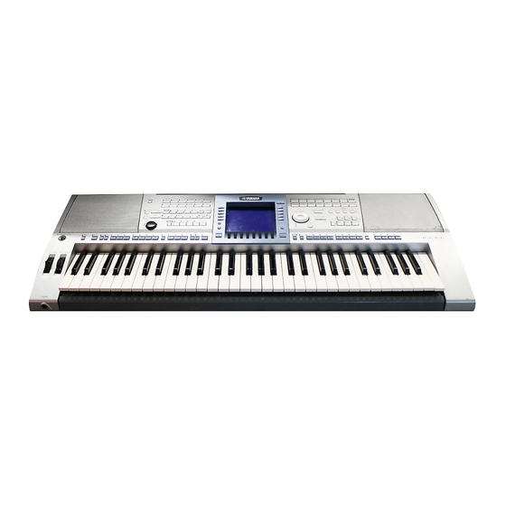
 ’04.06...
IMPORTANT NOTICE This manual has been provided for the use of authorized Yamaha Retailers and their service personnel. It has been assumed that basic service procedures inherent to the industry, and more specifically Yamaha Products, are already known and under- stood by the users, and have therefore not been restated.
PSR-1500/PSR-3000 SPECIFICATIONS PSR-1500 PSR-3000 Sound Source AWM Stereo Sampling Keyboard 61 keys (C1–C6 with Initial Touch) Display 320 x 240 dots QVGA B/W LCD 320 X 240 dots QVGA Color LCD Music Score, Lyrics Polyphony (max) 297 voices + 480 XG Voices...
Page 4
937 mm x 399 mm x 167 mm (38-5/16" x 15-11/16" x 6-9/16") Weight 10 kg (22 lbs., 1 oz) 11 kg (24 lbs., 4 oz) Guide to Yamaha Online Member Product User Registration, Accesory CD-ROM for Windows, Owner’s Manual, Data List, Accesory CD-ROM for Windows Installation Guide Accessories...
PSR-1500/PSR-3000 PANEL LAYOUT Rear view This figure shows the PSR-3000. REAR PANEL q [DC IN 16V] terminal w OUTPUT [L/L+R] / [R] jacks e AUX OUT (LEVEL FIXED) [L] / [R] jacks r AUX IN [L/L+R ] / [R] jacks t [MIC./LINE IN] jack (PSR-3000)
Page 6
PSR-1500/PSR-3000 Top view q [STANDBY/ON] switch @0 [KARAOKE] button @1 [REC] button WHEEL w [PITCH BEND] wheel @2 [STOP] button e [MODULATION] wheel @3 [PLAY/PAUSE] button @4 [REW]/[FF] buttons PHONES r [PHONES] @5 [PERFORMANCE ASSISTANT] button @6 [GUIDE] button t [DEMO] button...
Speaker grille L assembly Speaker grille R assembly Push knob Upper case assembly This figure shows the PSR-1500. [S50]: Bind Head Tapping Screw-B 3.0X8 MFZN2Y(EP600250) [430A]: Bind Head Tapping Screw-P 3.0X25 MFZN2Y(VK228100) [420]: Bind Head Tapping Screw-P 3.0X12 MFZN2Y(EP600300) [460A]: Bind Head Tapping Screw-B 3.0X8 MFZN2Y(EP600250)
Page 15
[460F] [570] [460F] [560C] Wheel Keyboard assembly [460B] *PSR-3000 (Shield cover L) This figure shows the PSR-1500. [570] [460F] [460F] [460F] [60]: Bind Head Tapping Screw-P 4.0X10 MFZN2Y(EP640500) [430B]: Bind Head Tapping Screw-P 3.0X25 MFZN2Y(VK228100) [440A] [440A]: Bind Head Tapping Screw-B 3.0X6 MFZN2BL(EP600230) [460F] [450]: Bind Head Tapping Screw-B 4.0X8 MFZN2BL(EG340190)
Page 16
[460J] [460J] When DM circuit board (PSR-1500) or DM2-E circuit board (PSR-3000) is replaced, data on Internet settings may be lost. DM circuit board (PSR-1500) and DM2-E circuit board (PSR-3000) have an internal DIP switch for switching the display in Japanese or in English (SW3).
Page 17
PSR-1500/PSR-3000 15-4. DM Circuit Board (PSR-1500) 15-6. DAC1A Circuit Board (PSR-1500) (Time required: About 8 minutes): (Time required: About 8 minutes): Remove the four (4) screws marked [460H]. The DM Remove the four (4) screws marked [460K]. The DAC1A circuit board can then be removed. (Fig. 3) circuit board can then be removed.
Page 18
Remove the two (2) screws marked [460G]. The shield then be removed. (Figs. 4, 5) cover U with the DM circuit board and DAC1A circuit board (PSR-1500) or with DM2-E circuit board and TG1 16-6. DJK Circuit Board (PSR-3000) circuit board (PSR-3000) can then be removed. (Fig. 3)
Page 19
17-9-2. Remove the four (4) screws marked [D60]. The DAC1A circuit board can then be removed. (Fig. 10) [560F] X 16 [560H] X 18 [560N] X 5 [560M] X 5 PNCR PNCL This figure shows the PSR-1500. [560]: Bind Head Tapping Screw-B 3.0X8 MFZN2Y(EP600250) (Fig. 9)
Page 20
PSR-1500/PSR-3000 17-10. LCD (Time required: About 11 minutes): 17-11-5. Remove the screw marked [560L] and the two (2) screws 17-10-1. Remove the PNCC circuit board. (See procedure 17-8.) marked [580]. The panel stay can then be removed. 17-10-2. Remove the DJK circuit board. (See procedures 16-5, 6.) (Fig.
Page 21
EMKSA (CN1) and DM (CN13) for 18-6-1. Remove the twenty-one (21) screws marked [140], then PSR-1500, or when connecting the EMKSA (CN1) remove the black keys from the lower notes. (Fig. 14) and DM2-E (CN16) for PSR-3000. Connecting the 18-6-2.
Page 22
PSR-1500/PSR-3000 Assembling the Keyboard Assembly 19-4. Install the rubber contacts while pulling the keys up. (Figs. 15, 16) 19-1. Install the white keys GEGB from the lower notes. When fitting the rubber contacts, raise both ends (Fig. 14) of the frame so that keys do not push the rubber 19-2.
PSR-1500/PSR-3000 LSI PIN DESCRIPTION M38869M8A-184GP (X5343100) CPU (PSR-3000) ............. 23 HD6417727F160C (X2890B00) CPU ..................24 HD6417709SHF200B (X2687A00) CPU (SH3) (PSR-3000) ..........25 HD6417709SHF200B (X2687B00) CPU (SH3) (PSR-3000) ..........25 M38044M4-C16FP (X4406100) CPU ..................26 µPD780031AYGK-NO4 (X0031200) CPU ................26 S1D13806F00A200 (X4029A00) LCDC (PSR-3000)............. 27 T8F02TB-0102 (X0060A00) SWP50 ................28/29...
Page 24
PSR-1500/PSR-3000 DM: IC007 (PSR-1500) HD6417727F160C (X2890B00) CPU DM2-E: IC006 (PSR-3000) NAME NAME FUNCTION FUNCTION Vcc-RTC PTM[4]/PINT[4]/AFE_RDET_/USB1d_TXDMNS Power supply for RTC (1.9V) Not in use XTAL2 Reserved/USB1d_SUSPEND Not in use (XTAL for internal RTC) EXTAL2 USB1_ovr_crnt/USBF_VBUS USB function VBUS Vss-RTC USB2_ovr_crnt_...
Page 25
PSR-1500/PSR-3000 HD6417709SHF200B (X2687A00) CPU (SH3) HD6417709SHF200B (X2687B00) CPU (SH3) TG1: IC001 (PSR-3000) NAME FUNCTION NAME FUNCTION CKE/PTK5 CK enable / Port K Mode control RAS3L/PTJ0 RAS address bus / Port J Vcc(RTC) Power supply +1.8 V PTJ1 Port J XTAL2...
Page 26
PSR-1500/PSR-3000 M38044M4-C16FP (X4406100) CPU PNR: IC100 NAME FUNCTION NAME FUNCTION Port6 / A-D converter input Port1 /INT Port5 / Interrupt input /PWM Port5 / PWM output /CNTR Port5 / Timer Y /CNTR Port5 / Timer X /INT Port1 / Interrupt input...
Page 27
PSR-1500/PSR-3000 S1D13806F00A200 (X4029A00) LCDC DM2-E: IC019 (PSR-3000) NAME FUNCTION NAME FUNCTION Power supply +3.3V Power supply +3.3V CNF2 FPFRAME Frame pulse CNF1 Configure the S1D13704 FPLINE Line pulse CNF0 not used TESTEN Test enable DRDY TFT / D-TFD display enable...
Page 28
PSR-1500/PSR-3000 DM: IC035 (PSR-1500) T8F02TB-0102 (X0060A00) SWP50 TG1: IC006 (PSR-3000) OUTER OUTER NAME FUNCTION NAME FUNCTION VSS2 Ground VSS2 Ground VDDC Power supply +1.5 V VDDC Power supply +1.5 V CD15 HMA15 CD13 HMA16 Wave memory address bus CD14 HMA22...
Page 29
PSR-1500/PSR-3000 OUTER OUTER NAME FUNCTION NAME FUNCTION AB22 VSS2 Ground VSS2 Ground AC23 VDDC Power supply +1.5 V VDDC Power supply +1.5 V AD24 DMAL1 Address bus (DIMM, SDRAM) MELI6 MEL wave data input AE25 DCSL2 MELI7 AF26 DRAS0 ADLR...
Page 30
PSR-1500/PSR-3000 S1L50553F21Y000 (X4195A00) Gate Array TG1: IC005 (PSR-3000) NAME FUNCTION NAME FUNCTION CLKI Power supply Clock CLKO RESET Reset Power supply Ground SCANENB Scan enable OUT4 Output ATPGENB OUT3 Ground INP2 PLLTEST Test INP1 Input PLLRES Reset INP0 PLLV Ground...
Page 31
PSR-1500/PSR-3000 AK4393VF-E2 (XW029A00) DAC DAC1A: IC301 NAME FUNCTION NAME FUNCTION DVSS Digital ground BVSS Substrate ground DVDD Digital power supply VREFL Low level voltage reference MCLK Master clock VREFH High level voltage reference Power down mode AVDD Analog power supply +5 V...
Page 36
PSR-1500/PSR-3000 DM Circuit Board (PSR-1500) Component side 2NA-WC02260-1...
Page 37
PSR-1500/PSR-3000 DM Circuit Board (PSR-1500) to AM-CN96 to SM-CN1 to DAC1A-CN101 to EMKSA-CN1 to AM -CN97 to PNR -CN100 to LCD installed installed to DJK -CN71 installed to DJK -CN75 • DIP Switch to DJK-CN72 to INV-CN500 to DJK-CN81 to DJK-CN73...
Page 38
PSR-1500/PSR-3000 DM2-E Circuit Board (PSR-3000) • DIP Switch to DJK-CN81 to DJK-CN72 to DJK-CN73 not installed to DJK-CN75 to DJK-CN71 to INV-CN500 Japanease English installed to LCD to EMKSA -CN1 to DJK -CN83 to PNR -CN100 to SM -CN1 installed...
Page 39
PSR-1500/PSR-3000 DM2-E Circuit Board (PSR-3000) Pattern side 2NA-WB76170-1...
Page 40
PSR-1500/PSR-3000 AM Circuit Board INPUT VOLUME (PSR-3000) MIC / LINE IN AUX IN MIC / LINE (PSR-3000) L / L+R AUX IN R (PSR-3000) to DAC1A-CN701 (PSR-3000) not installed (PSR-1500) to VR-CN13 to DAC1A-CN601 to Speakers (WOOFER) 2NA-WB82640-1...
Page 41
PSR-1500/PSR-3000 Addition of an ground wire 1. It twists 3 times after attachment. AUX OUT L / R AUX IN OUTPUT (LEVEL FIXED) L / L+R L / L+R OUTPUT R DC IN 16V to SW-CN94 to DM-CN15 (PSR-1500) to DM2-E-CN12...
Page 42
PSR-1500/PSR-3000 AM Circuit Board 2NA-WB82640-1...
Page 43
PSR-1500/PSR-3000 Pattern side 2NA-WB82640-1...
Page 45
PSR-1500/PSR-3000 TG1 Circuit Board (PSR-3000) Pattern side PNCC Circuit Board to PNCR-CN202 Pattern side PNCC: 2NA-WB94790-1 TG1: 2NA-WB82270-1...
Page 46
PSR-1500/PSR-3000 DJK Circuit Board to DM2-E-CN9 VIDEO OUT (PSR-3000) (PSR-3000) not installed (PSR-1500) FOOT PEDAL 2 to DM-CN2 (PSR-1500) to DM2-E-CN3 FOOT (PSR-3000) PEDAL 1 MIDI OUT to DM-CN1 (PSR-1500) to DM2-E-CN1 (PSR-3000) MIDI IN USB To to DM-CN4 HOST...
Page 47
PSR-1500/PSR-3000 DAC1A Circuit Board to AM-CN11 to DM1-CN17 (PSR-1500) (PSR-1500) to TG1-CN2 (PSR-3000) to AM-CN62 Component side Pattern side (PSR-3000) HP Circuit Board PHONES to AM-CN46 Component side Pattern side DAC1A: 2NA-WB55050-1 2NA-WB82640-1...
Page 49
PSR-1500/PSR-3000 VOICE (ORGAN FLUTES) VOICE VOICE UTE & WOODWIND) (ORGAN) MOD Circuit Board VOICE VOICE VOICE (USER) PERC. & DRUM KIT) (VOICE EFFECT) to PNL-CN107 MENU MENU MENU (SOUND CREATOR) (DIGITAL RECORDING 6) (FUNCTION) MODULATION PART SELECT Component side Pattern side...
Page 50
PSR-1500/PSR-3000 to PNL-CN109 to DM-CN12 (PSR-1500) to DM2-E-CN18 (PSR-3000) PB Circuit Board to PNL-CN106 PITCH BEND Component side Pattern side PNR Circuit Board PB, PNR: 2NA-WB94790-1...
Page 51
PSR-1500/PSR-3000 to PNCR-CN201 to PNL-CN110 to PNL-CN108 to ENC-CN301 Pattern side 2NA-WB94790-1...
Page 52
PSR-1500/PSR-3000 ENC Circuit Board DATA ENTRY to PB-CN401 DEMO to MOD-CN501 to PNR-CN105 Component side Pattern side SW Circuit Board METRONOME to AM-CN91 ON / OFF TAP TEMPO Component side Pattern side STANDBY / ON PNL Circuit Board STYLE CONT.
Page 53
PSR-1500/PSR-3000 PSR-3000 only to PNR-CN112 to PNCL-CN201 to PNR-CN113 to PNR-CN111 STYLE STYLE (BALLAD) STYLE (R & B) DEMO STYLE (DANCE) (COUNTRY) STYLE (SWING & JAZZ) STYLE STYLE (MOVIE & SHOW) (ENTERTAINER) STYLE (LATIN) STYLE (BALLROOM) STYLE (WORLD) STYLE (USER)
Page 55
PSR-1500/PSR-3000 INV Circuit Board to LCD-Backlight to AM- CN98 Pattern side to DM-CN3 (PSR-1500) to DM2-E-CN4 (PSR-3000) Be careful not to touch any Component side components due to a risk of high voltage. Pattern side INV, PNL: 2NA-WB85600-2...
Page 56
PSR-1500/PSR-3000 PNCR Circuit Board (LEFT) Select J Select F Select I Select H Select G (RIGHT) Component side to PNCC-CN301 to PNR-CN110 Pattern side 2NA-WB94790-1...
Page 57
PSR-1500/PSR-3000 PNCL Circuit Board to PNL-CN104 CHANNEL DIRECT LCD Select A LCD Select C LCD Select E ON / OFF ACCESS LCD Select B LCD Select D BALANCE Component side Pattern side 2NA-WB85600-2...
Page 58
PSR-1500/PSR-3000 MK-L Circuit Board to MK-H Component side EMKSA Circuit Board to MK-H to DM-CN13 (PSR-1500) MK-L: 2NA-VV58380 Component side to DM2-E-CN16 (PSR-3000) EMKSA: 2NAKZ-V766280...
Page 59
PSR-1500/PSR-3000 MK-H Circuit Board to EMKSA-CN3 to MK-L Component side EMKSA Circuit Board Pattern side MK-H: 2NA-VV583900 EMKSA: 2NAKZ-V766280...
001 : Version Checks each ROM version. This test program displays ROM's versions. Press the [TAB ] switch while displaying ROM's versions to move to the screen displaying the sub-versions. Case PSR-1500 Case PSR-3000 Model Name : PSR-1500(E) Model Name...
Page 61
PSR-1500/PSR-3000 LCD display Test descriptions, judging conditions, etc. 015 : Output R Check Checks R channel output. Connect the level meter (with a JIS-C filter) to each jack (PHONES L, R, OUTPUT L/L+R, R, AUX OUT (LEVEL FIXED) L, R) With [MASTER VOLUME] at the maximum, check the R channel output level.
Page 62
PSR-1500/PSR-3000 LCD display Test descriptions, judging conditions, etc. 028 : ALL Panel LED On Check Checks all the panel LEDs' lighting up. Confirm that all the panel LEDs will light up. The LEDs on the PNL side light up when [TAB ] switch is pressed.
Page 63
Checks ROM connected to CPU bus. (Complete check) Confirm that "ROM Check2 OK" is displayed on LCD. Check takes about 4 seconds for PSR-1500 and about 5 seconds for PSR-3000. 068 : RAM Check2 Checks RAM connected to CPU bus. (Complete check) Confirm that "RAM Check2 OK"...
Page 64
PSR-1500/PSR-3000 Switch Test Sequence (PSR-1500) Turn SW Name / Display Note number Turn SW Name / Display Note number DEMO POP&ROCK BALLAD DANCE SWING&JAZZ R&B COUNTRY LATIN BALLROOM MOVIE&SHOW ENTERTAINER WORLD USER METRONOME (BACK) TRANSPOSE- (NEXT) TRANSPOSE+ SONG SELECT REPEAT...
Page 65
PSR-1500/PSR-3000 Switch Test Sequence (PSR-3000) Turn SW Name / Display Note number Turn SW Name / Display Note number DEMO POP&ROCK BALLAD DANCE SWING&JAZZ R&B COUNTRY MIC SETTING LATIN BALLROOM MOVIE&SHOW ENTERTAINER WORLD USER TAB (BACK) METRONOME TAB (NEXT) TRANSPOSE-...
PSR-1500/PSR-3000 SAVING FILES This operation lets you save your original data (such as Songs and Voices you’ve created) to a file. After you’ve created a Song or Voice in the relevant SONG CREATOR or SOUND CREATOR display, press the [SAVE] display button.
PSR-1500/PSR-3000 RESTORING THE FACTORY-PROGRAMMED SETTINGS Restoring the Factory-programmed System While holding the C6 key (right-most key on the keyboard), turn the [POWER] button ON. This operation has the same result as and is a shortcut for the System Setup restore operation explained in step 2 of the following section.
Page 68
PSR-1500/PSR-3000 Checkmark the box of the item to be reset to the factory programmed settings by pressing the ] button. Press the [D] button to execute the Factory Reset operation for all checkmarked items. Saving and Recalling Your Original Settings as a Single File For the items below, you can save your Original Settings as a Single File for future recall.
DATA BACKUP For maximum data security Yamaha recommends that you copy or save your important data to separate storage media, such as a SmartMedia card or USB storage device. This provides a convenient backup if the internal memory is damaged.
INITIALIZING INTERNET SETTINGS The settings of the Internet function are not initialized when using the Initialize operation of the PSR-1500/3000; Internet settings must be initialized separately, as explained here. Initializing will reset to the default values not only the settings of the browser, but also all settings you have made in the Internet Settings displays (except for the cookies and bookmarks), including those related to Internet connection.
PSR-1500/PSR-3000 VERSION UPGRADE Download the version upgrade program from the Yamaha official website. List of the updating Flash ROM PSR-1500 Main Program IC21 PSR-3000 Main Program DM2-E IC47 How to Install Never turn the instrument off while installing. It may break the boot Flash ROM device.To repair it, you have to exchange the Flash ROM on board.
Page 72
Check that the version of Main Program on LCD is in agreement with the version of install data. Check that all items are set to OK. The version display on LCD. PSR-1500 PSR-3000 Version Overview Version Overview Model Name : PSR-1500 (E) Model Name : PSR-3000 (E) Main Boot : 1.00 Main Boot : 1.00 Main Program : 1.04...
Page 73
PSR-1500/PSR-3000 Trouble Shootings Turned off the instrument while installing. Pulling off the SmartMedia card while installing. Please retry to install. No information on LCD with booting install mode. The Flash ROM may be broken. You need to exchange the Flash ROM device on board.
PSR-1500/PSR-3000 SYSTEM BOOTING FLOWCHART PSR-1500 Factory Set? Power ON After turning on the power: FLAG = 1 L (*invisible) After exiting the test program: Force Format Mode Set CPU Resister Check BackUP Data & Cookie. Initialize Port Initialize If these are damaged, there /DACIC = L BackUP Data &...
Page 75
PSR-1500/PSR-3000 PSR-3000 Factory Set? Power ON After turning on the power: FLAG = 1 L (*invisible) Force Format Mode Set CPU Resister After exiting the test program: Check BackUP Data & Cookie. Initialize Port Initialize If these are damaged, there Initialize Enhancing port BackUP Data &...
PSR-1500/PSR-3000 MIDI DATA FORMAT Many MIDI messages listed in the MIDI Data Format are expressed in decimal numbers, binary numbers and hexadecimal numbers. Hexa-decimal numbers may include the letter “H” as a suffix. Also, “n” can freely be defined as any whole number.
PSR-1500/PSR-3000 MIDI CHANNEL MESSAGE (1) [MIDI] [Song Creator] MIDI Events Status byte 1st Data byte 2nd Data byte Voice MIDI Reception MIDI Transmission PLAY Status Data (HEX) Parameter Data (HEX) Parameter Regular/ Mic/Vocal Song Right1/ Keyboard Style Extra Right1/ M.Pad Style...
Page 79
PSR-1500/PSR-3000 [MIDI] [Song Creator] MIDI Events Status byte 1st Data byte 2nd Data byte Voice MIDI Reception MIDI Transmission PLAY Status Data (HEX) Parameter Data (HEX) Parameter Regular/ Mic/Vocal Song Right1/ Keyboard Style Extra Right1/ M.Pad Style Song Upper PLAY REW...
Page 80
PSR-1500/PSR-3000 MIDI CHANNEL MESSAGE (2) NRPN [MIDI] [Song Creator] NRPN Data Entry Parameter Data Range Voice MIDI Reception MIDI Transmission PLAY Regular/ Mic/Vocal Song Right1/ Keyboard Style Extra Right1/ M.Pad Style Song Upper PLAY From Drum/ Harmony Right2/ Right2/ Lower...
Page 81
PSR-1500/PSR-3000 [MIDI] [Song Creator] Data Entry Parameter Data Range Voice MIDI Reception MIDI Transmission PLAY Regular/ Mic/Vocal Song Right1/ Keyboard Style Extra Right1/ M.Pad Style Song Upper PLAY From Drum/ Harmony Right2/ Right2/ Lower panel Natural/ Left Left (Right1/ Organ...
Page 82
PSR-1500/PSR-3000 [MIDI] [Song Creator] Address Size Data Parameter Description XG Default Voice MIDI Reception MIDI Transmission PLAY Regular/ Mic/ Song Right1/ Keyboard Style Extra Right1/ M.Pad Style Song Upper PLAY From Drum/ Vocal Right2/ Right2/ Lower panel Natural/ Harmony Left...
Page 83
PSR-1500/PSR-3000 [MIDI] [Song Creator] Address Size Data Parameter Description XG Default Voice MIDI Reception MIDI Transmission PLAY Regular/ Mic/ Song Right1/ Keyboard Style Extra Right1/ M.Pad Style Song Upper PLAY From Drum/ Vocal Right2/ Right2/ Lower panel Natural/ Harmony Left...
Page 84
PSR-1500/PSR-3000 [MIDI] [Song Creator] Address Size Data Parameter Description Voice MIDI Reception MIDI Transmission PLAY Regular/ Mic/ Song Right1/ Keyboard Style Extra Right1/ M.Pad Style Song Upper PLAY From Drum/ Vocal Right2/ Right2/ Lower panel Natural/ Harmony Left Left (Right1/...
Page 85
PSR-1500/PSR-3000 MIDI Parameter Change table (SPECIAL EFFECT) PSR-1500 PSR-3000 [MIDI] [Song Creator] Address Size Data Parameter Description Voice MIDI Reception MIDI Transmission PLAY Regular/ Mic/ Song Right1/ Keyboard Style Extra Right1/ M.Pad Style Song Upper PLAY From Drum/ Vocal Right2/...
Page 86
PSR-1500/PSR-3000 [MIDI] [Song Creator] Address Size Data Parameter Description XG Default Voice MIDI Reception MIDI Transmission PLAY Regular/ Mic/ Song Right1/ Keyboard Style Extra Right1/ M.Pad Style Song Upper PLAY From Drum/ Vocal Right2/ Right2/ Lower panel Natural/ Harmony Left...
Page 87
PSR-1500/PSR-3000 [MIDI] [Song Creator] Address Size Data Parameter Description XG Default Voice MIDI Reception MIDI Transmission PLAY Regular/ Mic/ Song Right1/ Keyboard Style Extra Right1/ M.Pad Style Song Upper PLAY From Drum/ Vocal Right2/ Right2/ Lower panel Natural/ Harmony Left...
Page 88
PSR-1500/PSR-3000 MIDI Parameter Change table (DRUM SETUP) [MIDI] [Song Creator] Address Size Data Parameter Description XG Default Voice MIDI Reception MIDI Transmission PLAY Regular/ Mic/ Song Right1/ Keyboard Style Extra Right1/ M.Pad Style Song Upper PLAY From Drum/ Vocal Right2/...
Page 89
PSR-1500/PSR-3000 System Exclusive Messages (1) [GM1] ... GM Required Parameter [GM2] ... GM Level2 Required Parameter * Not received when Receive System Exclusive Message Parameters is set to off. * Not transmitted when Transmit System Exclusive Message Parameters is set to off.
Page 90
PSR-1500/PSR-3000 MIDI Event Data Format Voice MIDI Reception MIDI Transmission PLAY Regular/ Mic/ Song Right1/ Keyboard Style Extra Right1/ M.Pad Style Song Upper PLAY From Drum/ Vocal Right2/ Right2/ Lower panel Natural/ Harmony Left Left operations Organ Voice Controller F0 7F XN 09 03 0M CC PP RR ... F7...
Page 91
Voice Left Left Section Control F0 43 7E 00 ss dd F7 11110000 F0 = Exclusive status 01000011 43 = YAMAHA ID 01111110 7E = Style 00000000 00 = 0sssssss ss = Switch No. INTRO A INTRO B INTRO C...
Page 92
* Refer to XG Parameter Change Table. * Refer to XG Parameter Change Table. 11110000 F0 = Exclusive status 01000011 43 = YAMAHA ID 0001nnnn 1n = Device Number n = always 0 (when transmit), n = 0-F (when receive)
Page 93
F0 43 73 01 11 0n 50 00 dd F7 Pitch to Note ON/OFF 11110000 F0 = Exclusive status 01000011 43 = YAMAHA ID 01110011 73 = Clavinova ID 00000001 01 = Model ID (Clavinova common ID) 00010001 11 = Special Operators 0000nnnn 0n = Channel No.
Page 94
00H=Guide OFF 01H=Follow Lights 02H=Any Key 03H=Karao-Key 04H=Vocal CueTIME (Vocal Cue Time is not available on the PSR-1500.) Score F0 43 73 01 50 12 00 00 dd F7 Left Part indication On/Off 00H: OFF, 7FH: ON Entered to the song from the [SONG CREATOR] ->...
CONTENTS OVERALL ASSEMBLY ............. 2 UPPER CASE ASSEMBLY ............5 LOWER CASE ASSEMBLY ............8 KEYBOARD ASSEMBLY ............10 PSR-1500 ELECTRICAL PARTS........11-31 PSR-3000 ELECTRICAL PARTS........32-58 Notes : DESTINATION ABBREVIATIONS A : Australian model M : South African model...
Page 96
PSR-1500/PSR-3000 OVERALL ASSEMBLY Music rest This figure shows Japanese model. AC Adaptor (PA-300) PSR-1500 Upper case assembly: See page 5. 610 620 PSR-1500 PSR-1500 PSR-3000 DAC assembly Keyboard assembly: Lower case assembly: See page 10. See page 8. SM case assembly...
Page 108
PSR-1500 PART NO. DESCRIPTION REMARKS REF NO. RANK CN096 VB390000 Connector Base Post PH 4P TE CN097 LB918040 Base Post Connector XH 4P TE CN098 VB389800 Connector Base Post PH 2P TE D0059 VT332900 Diode 1SS355 TE-17 D0074 VT332900 Diode...
Page 154
< Page.2 > PSR-1500/PSR-3000 PSR-1500/PSR-3000 OVERALL CIRCUIT DIAGRAM (AM, HP, SW, VR) MIC / LINE PSR-3000 only MIC AMP OP AMP INPUT VOLUME OP AMP AUX IN MIC/LINE IN L/L+R 150‰~600‰ OP AMP OP AMP PSR-1500: not installed PSR-3000: to DAC1A-CN701 <Page.3 P-5>...
Page 155
< Page.3 > PSR-1500/PSR-3000 PSR-1500/PSR-3000 OVERALL CIRCUIT DIAGRAM (DAC1A, DJK, EMKSA, MK-H, MK-L) DAC1A OP AMP to AM-CN11 PSR-1500: to DM 2/2-CN17 <Page.2 C-7> <Page.5 P-8> PSR-3000: to TG1-CN2 PSR-1500: to DM 1/2-CN2 FOOT PEDAL <Page.10 B-6> <Page.4 B-6> PSR-3000: to DM2-E 1/2-CN3 OP AMP <Page.6 B-6>...
Page 156
< Page.4 > PSR-1500/PSR-3000 PSR-1500/PSR-3000 OVERALL CIRCUIT DIAGRAM (DM 1/2 (PSR-1500)) to LCD not installed to INV-CN500 <Page.8 E-10> to DJK-CN71 <Page.3 D-5> SYSTEM RESET INVERTER FLASH ROM 128M MAIN BUFFER BUFFER INVERTER INVERTER INVERTER <Page.5 G-2> INVERTER INVERTER to DJK-CN73 not installed <Page.3 F-4>...