Yamaha PSR-170 Service Manual
Hide thumbs
Also See for PSR-170:
- Service manual (26 pages) ,
- Owner's manual (68 pages) ,
- Owner's manual (64 pages)
Advertisement
Quick Links
SERVICE MANUAL
CONTENTS
SPECIFICATIONS .............................................................................. 3
PANEL LAYOUT ................................................................................. 4
BLOCK DIAGRAM ............................................................................. 5
CIRCUIT BOARD LAYOUT & WIRING .............................................. 6
DISASSEMBLY PROCEDURE .......................................................... 7
LSI PIN DESCRIPTION ................................................................... 10
IC BLOCK DIAGRAM ....................................................................... 11
CIRCUIT BOARDS .......................................................................... 12
TEST PROGRAM ............................................................................ 15
MIDI IMPLEMENTATION CHART .................................................... 17
OVERALL CIRCUIT DIAGRAM
PARTS LIST
This document is printed on chlorine free (ECF) paper with soy ink.
PK
001652
1.412K-355
Printed in Japan '01.05
Advertisement

Related Manuals for Yamaha PSR-170


Summary of Contents for Yamaha PSR-170
- Page 1 SERVICE MANUAL CONTENTS SPECIFICATIONS ................3 PANEL LAYOUT ................. 4 BLOCK DIAGRAM ................5 CIRCUIT BOARD LAYOUT & WIRING ..........6 DISASSEMBLY PROCEDURE ............7 LSI PIN DESCRIPTION ..............10 IC BLOCK DIAGRAM ............... 11 CIRCUIT BOARDS ................12 TEST PROGRAM ................15 MIDI IMPLEMENTATION CHART ............
- Page 2 PSR-170 IMPORTANT NOTICE This manual has been provided for the use of authorized Yamaha Retailers and their service personnel. It has been assumed that basic service procedures inherent to the industry, and more specifically Yamaha Products, are already known and understood by the users, and have therefore not been restated.
- Page 3 Large multi-function LCD display (backlit) VL/CSA 6-8W, CE7.5W (when using PA-3B power adaptor) Setup Power supply STANDBY/ON Adaptor : Yamaha PA-3B AC power adaptor MASTER VOLUME : MINI-MAX Batteries : Six “D” size, R20P(LR20) or equivalent batteries Panel controls Dimensions Overall, SONG, VOICE, STYLE, DEMO, POTABLE 931 x 348.8 x 127.9 mm (36-2/3"...
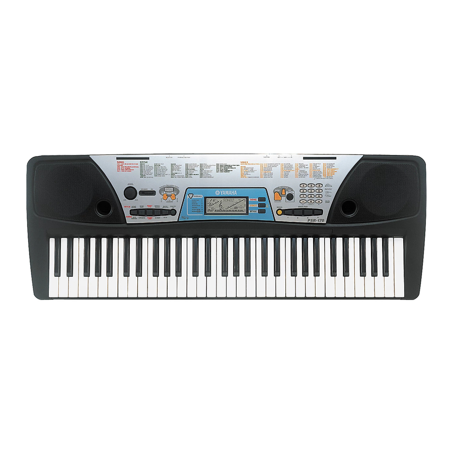
- Page 4 PSR-170 PANEL LAYOUT Top Panel GrandPno !3 !4 !5 !6 !7 !2 Numeric keypad, [+/ON] and [-/OFF] buttons q [MASTER VOLUME] dial w Power switch ([STANDBY/ON]) !3 [ACCOMPANIMENT ON/OFF] e LESSON [L] (Left) and [R] (Right) buttons ([A-B REPEAT]) button r [Dict.] (DICTIONARY) button...
- Page 6 PSR-170 CIRCUIT BOARD LAYOUT & WIRING Upper case side DM-LCD LCD Unit Speaker (L) Speaker (R) [WH105] [WH102] [C120] [WH203] [WH104] [WH103] [WH201] [WH204] PN-AM PN-AM [C120] [C130] Lower case side [M30] MK-L MK-H Location Part No. Connector Assembly Destination...
- Page 7 PSR-170 DISASSEMBLY PROCEDURE Lower Case Assembly 1-2. Remove the seven (7) screws marked [250] and the five (5) screws marked [260]. The lower case (Time required : About 3 min.) assembly can then be removed. (Fig. 1) 1-1. Remove the battery cover assembly. (Fig. 1)
- Page 8 PSR-170 PN-AM 1/2 Circuit Board PN-AM 2/2 Circuit Board (Time required : About 8 min.) (Time required : About 8 min.) 3-1. Remove the lower case assembly. (See procedure 1) 4-1. Remove the lower case assembly. (See procedure 1) 3-2.
- Page 9 PSR-170 White key and Black key pushing the hooks of it and slide the black key towards you. (Photo 1) (Time required : About 10 min. each) 8-3. When removing the C6 key, remove a screw 8-1. Remove the lower case assembly. (See procedure 1) marked [110B] and then lift the back of C6 key 8-2.
- Page 10 PSR-170 LSI PIN DESCRIPTION YMW728-F (XU355A00) GEW12 (AWM Tone Generator) DM-LCD : IC001 NAME FUNCTION NAME FUNCTION 51 DAC_Vdd Power supply Synch. signal Inicial Clear Port L Ground MA19 MA18 Memory address bus Power supply Power supply MA17 Port A...
- Page 11 PSR-170 S6A0069X10-Q0RJ (XV226A00) LCD DRIVER DM-LCD : IC006 NAME FUNCTION NAME FUNCTION Data interface Segment signal output for LCD driving Common signal output for LCD driving Ground OSC1 Oscillator OSC2 Oscillator Power supply CLK1 Data latch clock Segment signal output for LCD...
- Page 12 PSR-170 CIRCUIT BOARDS INDEX DM-LCD (XZ643B0) ................12 PN-AM 1/2 (XZ644B0) ................. 13 PN-AM 2/2 (XZ644B0) ................. 14 VR (XZ644B0) ..................14 DM-LCD Circuit Board to MK-L to PN-AM 1/2-CN102 to PN-AM 2/2-CN201 Component side Pattern side Note : See parts list for details of circuit board conponent parts.
- Page 13 PSR-170 PN-AM 1/2 Circuit Board PAUSE START/ REPEAT STOP ACMP SYNC START/ INTRO/ MAIN/ ON/OFF START STOP ENDING AUTO FULL LESSON LESSON STANDBY/ON OVERALL Dict. Component side PHONES/ DC IN 12V OUTPUT 2NA-V708340 4...
- Page 14 PSR-170 PN-AM 2/2 Circuit Board MULTI PAD/DJ GAME DEMO STYLE VOICE –/OFF 0/RESET +/ON PORTABLE GRAND SONG METRONOME to SPEAKER R Component side SUSTAIN MIDI VR Circuit Board to PN-AM 1/2-CN105 CN106 MASTER VOLUME Component side PN-AM 2/2, VR : 2NA-V708340 4...
- Page 15 PSR-170 TEST PROGRAM 1. PREPARATION 3. PROCEEDING THROUGH THE TEST 1) PA-3B or PA-3(AC adaptor) is used. PROGRAM 2) The volume is usually moved to the use position when 1) When the test program is started, “TEST” appears on the no volume change is required.
- Page 16 PSR-170 TEST No. LCD (initial) Test Functions and Judgment Criteria [028] LCD On Check that all LCD dots are on. [029] LCD Off Check that all LCD dots are off. [031] PD1 Chk Connect the foot switch (FC-4 or FC-5) to the [SUSTAIN] jack.
- Page 17 PSR-170 MIDI IMPLEMENTATION CHART YAMAHA [ PSR-170 ] Date:26-JAN-2001 Model PSR-170 MIDI Implementation Chart Version : 1.0 Transmitted Recognized Remarks Function... Basic Default 1 - 7,10 1 - 7,10 Channel Changed Default Mode Messages Altered ************** Note 0 - 127...
- Page 18 PARTS LIST CONTENTS OVERALL ASSEMBLY ..........................2 KEYBOARD ASSEMBLY ......................... 4 ELECTRICAL PARTS ........................5 – 8 Notes : DESTINATION ABBREVIATIONS Australian model South African model British model Chinese model Canadian model South-east Asia model German model Taiwan model European model U.S.A.
- Page 19 PSR-170 OVERALL ASSEMBLY Music Rest Lower Case Assembly LCD Unit C120 L110 L120 Keyboard Assembly L120 (See page 4.) C100 C110 C140 C130 C100 C140 120b C140 C140 120a Battery Cover Assembly...
- Page 20 PSR-170 PART NO. DESCRIPTION REMARKS REF NO. RANK OVERALL ASSEMBLY PSR-170 (V702380) V 7 0 2 4 0 0 0 Upper Case XZ871A00 Speaker 12.0cm 4 ohm 3W V 7 0 3 1 7 0 0 Panel Switch 3 DOME BLACK...
- Page 21 PSR-170 KEYBOARD ASSEMBLY MK Circuit Board Assembly Lower Case PART NO. DESCRIPTION REMARKS REF NO. RANK KEYBOARD ASSEMBLY 16N C61 P1M PSR-170 (V709960) White Keys 16N CEGBDFA V34107A0 White Keys 16N CEGB (V341260) White Keys 16N DFA (V341270) V 4 7 6 0 3 0 0...
- Page 22 PSR-170 ELECTRICAL PARTS PART NO. DESCRIPTION REMARKS REF NO. RANK ELECTRICAL PARTS PSR-170 V 6 9 2 5 2 0 0 Circuit Board DM-LCD (XZ643B0) VZ272400 Circuit Board MK-H 16N-1M (XT701A0) V 7 1 8 9 9 0 0 Circuit Board...
- Page 23 PSR-170 PART NO. DESCRIPTION REMARKS REF NO. RANK -0015 V 3 0 6 3 4 0 0 Chip Inductance BLM11B601S 1608 R0016 RD356220 Carbon Resistor (chip) 2.2K 63M J R0017 RD357910 Carbon Resistor (chip) 91K 63M J R0018 RD356220 Carbon Resistor (chip) 2.2K 63M J...
- Page 24 PSR-170 PART NO. DESCRIPTION REMARKS REF NO. RANK C0114 VE326200 Monolithic Mylar Capacitor 0.15 50V J C0114 VR168500 Monolithic Mylar Capacitor ECQ-V1H154JL3 C0115 UR839100 Electrolytic Cap. 1000 16.0V C0116 UR839100 Electrolytic Cap. 1000 16.0V C0117 UR837470 Electrolytic Cap.
- Page 25 PSR-170 PART NO. DESCRIPTION REMARKS REF NO. RANK WH105 Connector Assembly VR 5P-90 (V719680) WH201 Connector Assembly MIDI 6P-110 (V719690) WH203 Connector Assembly PN1 12P-110 (V719720) WH204 Connector Assembly SP 2P-140 (V719660) ZD101 VG437700 Zener Diode MTZ J 5.6B 5.6V...
- Page 26 PSR-170 PSR-170 OVERALL CIRCUIT DIAGRAM PN-AM DM-LCD MIDI IN MIDI OUT SUSTAIN SPEAKER MK-L LCD DRIVER PHOTO COUPLER MK-H MIDI DRIVER PN-AM POWER AMP MASTER VOLUME GEW-12 PHONES/ OUTPUT RESET ROM 16M PROGRAM STYLE WAVE SPEAKER STANDBY/ON BUFFER REGULATOR +3.3V...
Need help?
Do you have a question about the PSR-170 and is the answer not in the manual?
Questions and answers