New Rock Technologies HX4E User Manual
Mx series voice gateway
Hide thumbs
Also See for HX4E:
- User manual (94 pages) ,
- User manual (129 pages) ,
- User manual (125 pages)

Related Manuals for New Rock Technologies HX4E


Summary of Contents for New Rock Technologies HX4E
-
Page 1: User Manual
MX Series Voice Gateway User Manual New Rock Technologies, Inc. MX Series Voice Gateway User Manual HX4E MX8A MX60 MX120 MX120G Website: http://www.newrocktech.com Email: gs@newrocktech.com Document Version: 201606... -
Page 2: Amendment Records
This manual is applicable to New Rock’s MX series Voice Gateway V344. Copyright © 2016 New Rock Technologies, Inc. All Rights Reserved. All or part of this document may not be excerpted, reproduced and transmitted in any form or by any... -
Page 3: Table Of Contents
2.3.8 FoIP ................................. 33 2.4 Line ..................................35 2.4.1 Phone Number ............................35 2.4.2 Subscriber Line Features......................... 36 2.4.3 Subscriber Line Batch (Unavailable on the HX4E) .................. 38 2.4.4 Subscriber Line Characteristics ....................... 39 2.5 Trunk ................................... 42 2.5.1 Phone Number ............................42 2.5.2 Trunk Features ............................ - Page 4 2.7.2 Auto Provisioning ............................. 56 2.7.3 Management System Type ........................57 2.7.4 Security Configuration ..........................58 2.7.5 VPN (Available on the HX4E/MX8A) ....................... 59 2.7.6 Certificate ..............................60 2.7.7 White list for Accessing Web and Telnet ....................61 2.7.8 Media Stream ............................61 2.7.9 SIP Configuration ............................
- Page 5 MX Series Voice Gateway User Manual 4 Making an OpenVPN Client Certification ....................99 5 Appendix: High availability configuration....................102 6 Appendix: Auto provisioning configuration ..................103 New Rock Technologies, Inc.
-
Page 6: Contents Of Figure
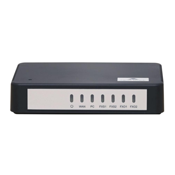
User Manual MX Series Voice Gateway Contents of Figure Figure 1-1 HX4E Front Panel ............................3 Figure 1-2 HX4E Back Panel ............................4 Figure 1-3 MX8A Front Panel ............................. 5 Figure 1-4 MX8A Back Panel ............................6 Figure 1-5 RJ45 to RS232 Serial Cable ........................6 Figure 1-6 USB to RS232 Converter Cable ........................ - Page 7 Figure 3-91 RTP Data Packet Carrying VLAN Tag of the Voice VLAN in the Multi-Service VLAN Mode ....98 Figure 3-92 RTP Data Packet Carrying VLAN Tag of the Management VLAN in the Multi-Service VLAN Mode ..98 New Rock Technologies, Inc.
-
Page 8: Contents Of Table
Table 1-1 MX Series Gateway Hardware Specifications ..................... 1 Table 1-2 Configuration Combination of HX4E ......................3 Table 1-3 Description of HX4E Front Panel ........................ 3 Table 1-4 Description of HX4E Back Panel ........................ 4 Table 1-5 Indicator Status of HX4E..........................4 Table 1-6 Configuration Combination of MX8A ...................... - Page 9 Table 2-32 Call Progress Tone Configuration Parameters ..................70 Table 2-33 Feature Codes Configuration Parameter ....................72 Table 2-34 Clock Service Parameters ........................74 Table 2-35 System Status Parameters ........................77 Table 2-36 Log Management Configuration Parameters ..................79 New Rock Technologies, Inc.
-
Page 10: Overview
To be used as remote access equipment for IP-PBXs in call center deployment The MX family has four sub-series: HX4E, MX8A, MX60, MX120 and MX120G, which mainly differ in port capacities. Table 1-1 MX Series Gateway Hardware Specifications... -
Page 11: Functions And Features
Support Web GUI-based management , Telnet/SSH, automatic software upgrades, and configuration downloading Support high availability, implementing a cloud of SIP servers working in primary-standby or load balancing mode Support auto provisioning Support security settings such as whitelists New Rock Technologies, Inc. -
Page 12: Equipment Structure
1.3 Equipment Structure 1.3.1 HX4E The HX4E adopts a compact plastic structural design and can be placed on a desk. It provides either two or four FXS/FXO ports. The HX4E supports the following models. Table 1-2 Configuration Combination of HX4E... -
Page 13: Figure 1-2 Hx4E Back Panel
User Manual MX Series Voice Gateway Figure 1-2 HX4E Back Panel Table 1-4 Description of HX4E Back Panel Item Description Power interface, 12 VDC input PC and The PC port is used to connect a computer. The WAN port is used to connect the uplink network. -
Page 14: Mx8A
Number of FXS Ports Number of FXO Ports 401A-4FXS 401A-4FXO 401A-2FXS/2FXO Figure 1-3 MX8A Front Panel Table 1-8 Description of MX8A Front Panel Item Description Power indicator Status indicator WAN interface indicator PC interface indicator VOICE FXS/FXO port indicator New Rock Technologies, Inc. -
Page 15: Figure 1-4 Mx8A Back Panel
The device is powered off or a power supply fault occurred. The WAN interface failed to acquire the IP address. Possibly the WAN Steady red (red, green) interface is not connected to a network cable, the WAN interface New Rock Technologies, Inc. -
Page 16: Mx60
The interface card of MX60 uses a RJ-45 socket and is connected to the distribution panel in equipment room using CAT-5 cables supplied with the unit. MX60 offers up to 48 interfaces of FXS/FXO. MX60 supports the following types of configuration. New Rock Technologies, Inc. -
Page 17: Figure 1-7 Mx60 Front Panel
Table 1-13 Pin Specifications for MX60 RJ45 Socket Port RJ45 Pin Number Pair Pair Pair Pair Pair Analog line pair TIP1 RING1 TIP2 TIP3 RING3 RING2 TIP4 RING4 Orange Green Blue Brown Reference color Orange Blue Green Brown white white white white New Rock Technologies, Inc. -
Page 18: Figure 1-8 Schematic Diagram Of Mx60 Subscriber Line Connection
Two 10/100 Mbps Ethernet ports (RJ45). They share one IP address, which by default is 192.168.2.240, and you can change it on Basic > Network page. Cooling fan AC power socket, 100-240 VAC voltage input. DC power socket, -48 VDC input. New Rock Technologies, Inc. -
Page 19: Mx120
Table 1-17 Configuration Combination of MX120 Models Number of FXS Ports Number of FXO Ports Concurrent calls MX120-NA-C-2U MX120-NA-D-2U Depend on the models and number of the interface cards. MX120-NA-E-2U MX120-NA-F-2U Figure 1-11 MX120 Front Panel New Rock Technologies, Inc. -
Page 20: Figure 1-12 Schematic Diagram Of Mx120 Subscriber Line Connection
Pair Pair Analog line pair TIP1 RING1 TIP2 TIP3 RING3 RING2 TIP4 RING4 Orange Green Blue Brown Reference color Orange Blue Green Brown white white white white Figure 1-12 Schematic Diagram of MX120 Subscriber Line Connection New Rock Technologies, Inc. -
Page 21: Figure 1-13 Mx120 Back Panel-Ac
Usually, this mode is entered when some prompts are required to give operator during equipment startup, diagnosis or operation. In this mode, LED flashes to display numbers, letters or other patterns in matrix. Please refer to Table 1-23. Figure 1-13 MX120 Back Panel-AC New Rock Technologies, Inc. -
Page 22: Figure 1-14 Mx120 Back Panel-Dc
Alarms existed and all alarm information confirmed Table 1-23 MX120 System Operation State Glittery letter Status meaning The IP address of gateway conflicts with that of other equipment in LAN. Please settle this problem before the gateway can be operated normally. New Rock Technologies, Inc. - Page 23 The gateway is in progress of system software upgrade. Please guarantee stable power supply and do not conduct other operations during this period. The application software of gateway has been exited. If it cannot be restored by rebooting the system, please contact your local distributor for further diagnosis. New Rock Technologies, Inc.
-
Page 24: Mx120G
MX120G-NA-X-1DC X=E, it is 72 Dual DC power MX120G-NA-X-2DC X=F, it is 96 Figure 1-15 MX120G Front Panel Table 1-26 Description of MX120G Front Panel Item Description Matrix of 6x4 LED status indicator on interface card New Rock Technologies, Inc. -
Page 25: Figure 1-16 Schematic Diagram Of Mx120G Subscriber Line Connection
Table 1-28 Corresponding Relation Between MX120G RJ45 Socket and Line Number RJ45 Socket No. (From Left to Right) 1 4 5 8 9 12 13 16 17 20 21 24 Line No. of This Card New Rock Technologies, Inc. -
Page 26: Figure 1-17 Mx120G Back Panel-Ac
In this mode, LED flashes to display numbers, letters or other patterns in matrix. Please refer to Table 1-31. Figure 1-17 MX120G Back Panel-AC Figure 1-18 MX120G Back Panel-DC New Rock Technologies, Inc. -
Page 27: Table 1-29 Mx120G Back Panel
A physical connection is established without any traffic. (green) (left side) Blinking green A physical connection is established with traffic. (left side) No connection is established. (left side) Steady green The USB device is detected. (green) The USB device is not detected. New Rock Technologies, Inc. -
Page 28: Table 1-31 Mx120G System Operation State
IP address conflicts Blinking with D The severe starting failure needs to address by your dealer Blinking with E Network failure Blinking with P Software upgrading Blinking with T App exited (The device cannot be used normally) New Rock Technologies, Inc. -
Page 29: Parameters Setting
2.1 Login 2.1.1 Obtaining Gateway IP Address MX8A/HX4E Gateways start DHCP service by default, and automatically obtain an IP address on the LAN; you can use the factory-default gateway IP address if it is unable to be obtained (e.g. when connected directly with a computer). -
Page 30: Gateway Administrator And Operator Rights
Google Chrome. The IE browser is used as an example below. The HX4E/MX8A is only allowed to access using HTTPS. Since the factory default certificate is used a prompt like "There is a problem with this website's security certificate" may occur. Click Continue to this website to access the login page. -
Page 31: Buttons Used On Gateway Management Interface
User Manual MX Series Voice Gateway Advanced > Security System tool > Change password System tool > Software upgrade System tool > Import data System tool > Export data After login, "Welcome user” is displayed on the upper left corner of the interface. The gateways allow multiple users to log in if needed. -
Page 32: Network
The subnet mask is used with an IP address. When the gateway uses a static IP address, this parameter must be entered; when an IP address is automatically obtained through DHCP, the system will display the subnet mask automatically obtained by DHCP. It has no default value. New Rock Technologies, Inc. -
Page 33: Vlan
User Manual MX Series Voice Gateway Name Description Default gateway The IP address of LAN gateway. When the gateway obtains an IP address through DHCP, the system will display the LAN gateway address automatically obtained through DHCP. It has no default value. -
Page 34: Figure 2-22 Vlan Configuration Interface
Multi-service VLAN: The device can configure different VLAN information for the voice service (SIP signaling and RTP/T.38 media stream) and the management service (HTTP/HTTPS, Telnet) and includes a different VLAN tag in a data packet of a different service. New Rock Technologies, Inc. -
Page 35: System
User Manual MX Series Voice Gateway Name Description Voice VLAN VLAN to which the voice service (SIP signaling and RTP/T.38 media stream) belongs. None: disable the voice VLAN Mode 1: SIP and RTP/T.38 are on the same VLAN Mode 2: SIP and RTP/T.38 are on different VLANs ... -
Page 36: Figure 2-23 System Configuration Interface
The gateways provide the following processing modes after detecting hook flash from subscriber terminals: Internal: the hook flash event will be handled internally; Server(RFC 2833): transmitting the hook flash to platform with RFC 2833; Server (SIP INFO): transmitting the flash-off to platform with SIP INFO. New Rock Technologies, Inc. -
Page 37: Sip
User Manual MX Series Voice Gateway Name Description DTMF transmission Transmission modes of DTMF signal supported by the gateways include RFC 2833, Audio and method SIP INFO. The factory default value is RFC 2833. RFC 2833: separate DTMF signal from sessions and transmit it to the platform through RTP ... -
Page 38: Figure 2-24 Sip Configuration Interface
This domain name will be used in INVITE messages. If it is not set here, the gateways will use the name IP address or domain name of the proxy server as the user-agent domain name. It has no default value. New Rock Technologies, Inc. -
Page 39: High Availability
User Manual MX Series Voice Gateway Name Description Registrar mode The gateway supports three registration schemes: Per line (default): authenticate and register per line. Per gateway: authenticate and register per gateway. Per line/GW auth: Enable registration per line. Use the number configuration per line. Use the ... -
Page 40: Mgcp
The gateways use SIP protocol by default. When the gateways need to interface with MGCP protocol - based soft switch platform, set the relevant parameters here. After login, click Basic > MGCP to open the configuration interface. New Rock Technologies, Inc. -
Page 41: Figure 2-26 Mgcp Configuration Interface
User Manual MX Series Voice Gateway Figure 2-26 MGCP Configuration Interface Table 2-9 MGCP Configuration Parameters Name Description Local port Configure the UDP port for transmitting and receiving MGCP messages, the default value is 2427. Note: The signaling port number can be set in the range of 1-9999, but cannot conflict with the other port numbers used by the equipment. -
Page 42: Foip
Select if a package name is included when the gateways reply to the default package. Default not selected. Keep connection when on- Select if the gateways actively cancel connection disconnect when subscribers hook on. hook Default not selected. 2.3.8 FoIP After login, click Basic > FoIP to open this interface. New Rock Technologies, Inc. -
Page 43: Figure 2-27 Fax Configuration Interface
User Manual MX Series Voice Gateway Figure 2-27 Fax Configuration Interface Table 2-10 Fax Configuration Parameters Name Description Initial offer Codec Click Edit, go to Basic > System page to configure. For details, see 2.3.4 System. RTP port Min. Click Edit, go to Advanced > Media stream page to configure. For details, see 2.7.8 Media Stream. -
Page 44: Line
Line 2 increases 1 progressively based on that of Line 1, and so on. ID n Fill in the telephone number associated with the subscriber line n (FXS port). This should be manually performed if Batch mode is not used. New Rock Technologies, Inc. -
Page 45: Subscriber Line Features
User Manual MX Series Voice Gateway 2.4.2 Subscriber Line Features The content below is only applicable to gateways with FXS ports. After login, click Line > Feature to open the configuration interface. Figure 2-29 Subscriber Line Features Configuration Interface Table 2-12 Subscriber Line Features Configuration Parameters Name Description Fill in the port number associated with this port. - Page 46 Note: This parameter is displayed only when IMS is selected and Registration subscription is checked on Advanced > SIP page. Call waiting Select if Call waiting is activated on this line. By default this is not selected. New Rock Technologies, Inc.
-
Page 47: Subscriber Line Batch (Unavailable On The Hx4E)
Recording Select if recording service is activated, and by default this is not selected. 2.4.3 Subscriber Line Batch (Unavailable on the HX4E) The content below is only applicable to gateways with FXS ports. After login, click Line > Batch to open the configuration interface. -
Page 48: Subscriber Line Characteristics
MX Series Voice Gateway User Manual Figure 2-30 Feature Batch Configuration Interface 2.4.4 Subscriber Line Characteristics The content below is only applicable to gateways with FXS ports. After login, click Line > feature to open the configuration interface. New Rock Technologies, Inc. -
Page 49: Figure 2-31 Subscriber Line Characteristics Configuration Interface
User Manual MX Series Voice Gateway Figure 2-31 Subscriber Line Characteristics Configuration Interface Table 2-13 Subscriber Line Characteristics Configuration Parameter Name Description Gain to IP Adjust the voice volume from the analog extension. The default is 0. Taking decibel as the unit, setting range is -3 ~ +3 decibels. - Page 50 Set the parameter Alert-Info n according to the “Alert-Info” value provided on the SIP server. Distinctive When the “Alert-info” value of received INVITE message matches with the Alert-Info n, ring Alert/Ringing cadence n is activated. Alert-Info 1 Match with ring cadence 1. New Rock Technologies, Inc.
-
Page 51: Trunk
User Manual MX Series Voice Gateway Name Description Configure ring Configure ring patterns for ring cadence 1. patterns for ring e.g. 1: if the ring patterns are set to 2, 500, 500, 1000, 3000, the ringing cadence is 0.5s on, 0.5s cadence 1 off;... -
Page 52: Trunk Features
Note: This parameter is displayed only when Multi port is checked on Advanced > SIP page. Registration Select if this trunk registers with the SIP registration server. By default, this is not selected. Password If Registration is selected, the authentication password for registering this line must be entered here. New Rock Technologies, Inc. -
Page 53: Trunk Batch (Unavailable On The Hx4E)
Recording Select if recording service is activated. This is not selected by default. 2.5.3 Trunk Batch (Unavailable on the HX4E) Only a gateway with FXO ports can display this interface. After login, click Trunk > Batch to open the configuration interface. -
Page 54: Trunk Characteristics
MX Series Voice Gateway User Manual Figure 2-34 Trunk Batch Configuration Interface 2.5.4 Trunk Characteristics Only a gateway with FXO ports can display this interface. After login, click Trunk > Advanced to open the configuration interface. New Rock Technologies, Inc. -
Page 55: Figure 2-35 Trunk Characteristics Configuration Interface
User Manual MX Series Voice Gateway Figure 2-35 Trunk Characteristics Configuration Interface Table 2-16 Trunk Characteristics Configuration Parameter Name Description Gain to IP Adjust the volume of the voice sent from the PSTN to the device. Increase the value when the volume received by internal party is low. Range: -3.0 - +9.0 dB. -
Page 56: Routing
If Detect dual-frequency busy tones is enabled, you need to specify the frequency to be detected. Unit: Hz. 2.6 Routing 2.6.1 Digit Map After login, click Routing > Digit Map to open the dialing rules interface. New Rock Technologies, Inc. -
Page 57: Figure 2-36 Configuration Interface For Digit Map
User Manual MX Series Voice Gateway Figure 2-36 Configuration Interface for Digit Map Dialing rules are used to effectively detect completed received number sequences that are ready to be sent in order to reduce connection time of telephone calls. The maximum number of rules that can be stored in gateways is 250. Each rule can hold up to 32 numbers and 38 characters. -
Page 58: Routing Table
Dial rules by default are as follows: 01[3-5,7,8]xxxxxxxxx 010xxxxxxxx 02xxxxxxxxx 0[3-9]xxxxxxxxxx 11[0,2-9] 111xx 123xx 95105xxx 95xxx 100xx 1[3-5,7,8]xxxxxxxxx [2-3,5-7]xxxxxxx 8[1-9]xxxxxx 80[1-9]xxxxx 800xxxxxxx 4[1-9]xxxxxx 40[1-9]xxxxx 400xxxxxxx xxxxxxxxxx.T 2.6.2 Routing Table After login, click Routing > Routing Table to open the configuration interface. New Rock Technologies, Inc. -
Page 59: Figure 2-37 Routing Table Configuration Interface
User Manual MX Series Voice Gateway Figure 2-37 Routing Table Configuration Interface Click to open the illustrative interface for routing configuration. The routing table with a capacity of 500 rules provides two functions including number transformation and call routing assignment. The device will match a rule from top to bottom. -
Page 60: Table 2-18 Routing Table Format
Add 8888 at the end of the calling number starting with 6120 for calls from an FXS (Phone/fax) port. REPLACE Number replacement. The replacing number follows REPLACE. Example: FXS CPN88 REPLACE 2682000 Replace the calling number beginning with 88 for calls from FXS port with 2682000. New Rock Technologies, Inc. -
Page 61: Table 2-20 Routing Destination
User Manual MX Series Voice Gateway Processing Description and Example Mode REPLACE Another use of REPLACE is to replace the specific number based on another number associated with the call. For example, replacing the calling number according to the called number. (continued) Examples: 12345... -
Page 62: Examples Of Routing Rules
Assigning One Phone with Dual Numbers For example, an analog extension of an FXS port, FXS1, of HX4E can be associated with two phone numbers: a PSTN number 61202701 and an extension number 1001. The PSTN number is used for direct inward dialing and the extension number is used for intercom. -
Page 63: Ip Table
User Manual MX Series Voice Gateway Routing Setting Description FXS[1] 0 ROUTE NONE A calling starting with 0 is barred from dialing using the phone set at FXS1 port FXS[1-2] 00 ROUTE NONE A calling starting with 00 is barred from dialing using the phone set at FXS1 to FXS2 port. -
Page 64: Figure 2-39 Interface Of System Advanced Configuration
With seconds as its unit, default value of 60 seconds. SDP Address NAT IP Address: Use NAT public address. Local IP Address: Use the gateway’s IP address. Note: NAT IP Address is effective when the device successfully obtains NAT public address. New Rock Technologies, Inc. -
Page 65: Auto Provisioning
Input a password for accessing the ACS. Firmware upgrade Supports firmware download and update using ACS. Note: For the HX4E/MX8A, the firmware can be a tar.gz file or an img file. For the MX60/MX120/120G, the firmware is always a tar.gz file. Update mode The following modes are available. -
Page 66: Management System Type
Server Enter the address of the SNMP server. Trap port Enter the port number of the SNMP server. The default value is 162. Notification interval The default value is 900 seconds. Figure 2-42 TR069 Configuration Interface New Rock Technologies, Inc. -
Page 67: Security Configuration
User Manual MX Series Voice Gateway Table 2-24 TR069 Configuration Parameters Name Description ACS-URL Specify the URL of the ACS. User name Set the user name used by the device to authenticate with the ACS. Password Set the password used by the device to authenticate with the file server Provisioning code Information of the device vendor, which may be used to indicate the primary service provider and other provisioning information to the ACS. -
Page 68: Vpn (Available On The Hx4E/Mx8A)
VPN client need to be deployed instead, which greatly reduces the network expense. With a built-in VPN client, the HX4E/MX8A is ready to be directly connected to the VPN server to avoid the firewall issues and NAT issues. -
Page 69: Certificate
User Manual MX Series Voice Gateway Figure 2-44 VPN Configuration Interface Table 2-26 VPN Configuration Parameters Name Description Enable VPN client function. Type Disable VPN, or select L2TP or OpenVPN. VPN server Enter the IP address of the L2TP VPN server. User name Enter the user name provided by the L2TP VPN server. -
Page 70: White List For Accessing Web And Telnet
Being accessible by using Telnet/SSH requires to enable Telnet/SSH on Advanced > Security page. The device allows a white list of 20 entries. 2.7.8 Media Stream After login, click Advanced > Media Stream to open this interface. New Rock Technologies, Inc. -
Page 71: Sip Configuration
User Manual MX Series Voice Gateway Figure 2-47 Media Stream Configuration Interface Table 2-27 Media Stream Configuration Parameter Name Description RTP port Min. The lowest port number of UDP ports for RTP transmission and receiving. The parameter must be greater than or equal to 3000. This is a required field. Note: each phone call will occupy RTP and RTCP ports. -
Page 72: Figure 2-48 Sip Related Configuration Interface
SDP etc. MX gateways provide flexibility in field setting in order to improve compatibility with the SIP register server. After login, click Advanced > SIP to open this interface. Figure 2-48 SIP Related Configuration Interface New Rock Technologies, Inc. -
Page 73: Table 2-28 Sip Related Configuration Parameter
User Manual MX Series Voice Gateway Table 2-28 SIP Related Configuration Parameter Name Description SIP related configuration The default is 86400 seconds. Set the time interval for which MWI service subscription request MWI subscription will be sent to the SIP server. This parameter should be used in conjunction with voice mail interval subscription on the page of the subject subscriber line. - Page 74 INVITE transaction timeout timer. It is 16000 ms by default. Timer D Wait time for response retransmits. It is 16000 ms by default. Timer E non-INVITE request retransmit interval, UDP only. It is 500 ms by default. New Rock Technologies, Inc.
-
Page 75: Radius (Unavailable On The Hx4E)
Protocol type transmission type. Specify the local port used by SIP/TCP. Local TCP port 2.7.10 RADIUS (Unavailable on the HX4E) After login, click Advanced > RADIUS to open this interface. Figure 2-49 RADIUS Configuration Interface Table 2-29 RADIUS Configuration Parameter... -
Page 76: Encryption
2.7.11 Encryption After login, click Advanced > Encryption to open this interface. Figure 2-50 Encryption Configuration Interface Table 2-30 Encryption Configuration Parameters Name Description Signal encryption Choose whether to encrypt signaling. By default, this is not selected. New Rock Technologies, Inc. -
Page 77: Greeting
User Manual MX Series Voice Gateway Name Description Encryption method Set the gateway encryption method, default is 7. The optional parameters as below: 2:TCP not encrypted 3: TCP encrypted 6: UDP not encrypted 7: UDP encrypted 8: Using keyword ... -
Page 78: Call Progress Tone Plan
If you want to delete the current color ringback tone, you can click Delete. After the gateway restarts, the default color ringback tone will be used. 2.7.13 Call Progress Tone Plan After login, click Advanced > Tones to open this interface. New Rock Technologies, Inc. -
Page 79: Figure 2-52 Call Progress Tone Configuration Interface
User Manual MX Series Voice Gateway Figure 2-52 Call Progress Tone Configuration Interface Table 2-32 Call Progress Tone Configuration Parameters Name Description Country/Region There are progress tone plans for several countries and regions that are pre-programmed in gateways. Users may also specify the tone plan according to the national standard. Gateways provide tone plans for the following countries and regions: China, the United States, France, Italy, Germany, Mexico, Chile, Russia, Japan, South Korea, Hong Kong, Taiwan, India, Sudan, Iran, Algeria, Pakistan, Philippines, Kazakhstan, Singapore, Israel,... -
Page 80: Feature Codes
This is illustrated with the following defaults for various parameters, which may be modified according to requirements. It is highly recommended not to modify the default configuration in System feature codes. Figure 2-53 Feature Codes Configuration Interface New Rock Technologies, Inc. -
Page 81: Table 2-33 Feature Codes Configuration Parameter
User Manual MX Series Voice Gateway Table 2-33 Feature Codes Configuration Parameter Name Description System feature codes Obtain IP address The function key for obtaining the IP address of gateway, with a default of ##. When this function key is dialed, the phone will play the device IP address, the web port number for accessing the device, the IP address of the gateway, the subnet mask, and the system software version number. -
Page 82: Clock Service
While listening, you can press a two-digit CRBT index to change to another CRBT file. Three-way calling The default value is *79. 2.7.15 Clock Service After login, click Advanced > System time to open this interface. Figure 2-54 Clock Service Interface New Rock Technologies, Inc. -
Page 83: Table 2-34 Clock Service Parameters
User Manual MX Series Voice Gateway Table 2-34 Clock Service Parameters Name Description Time Zone Select a time zone, the parameter values include: (GMT-11:00) Midway Island (GMT-10:00) Honolulu. Hawaii (GMT-09:00) Anchorage, Alaska (GMT-08:00) Tijuana (GMT-06:00) Denver ... -
Page 84: Status
After login, click Call Status > Call history on FXS to open this interface. Figure 2-56 Interface of Call History on FXS 2.8.3 Call History on FXO After login, click Call Status > Call history on FXO to open this interface. New Rock Technologies, Inc. -
Page 85: Sip Message Count
User Manual MX Series Voice Gateway Figure 2-57 Interface of Call on FXO 2.8.4 SIP Message Count After login, click Call Status > SIP message count to open this interface. Figure 2-58 SIP Message Count Interface 2.9 Logs 2.9.1 System Status Critical runtime information of gateways can be obtained in this interface, including: Information regarding login interface (including IP address and permissions of the user) ... -
Page 86: Figure 2-59 System Status Interface
No response: no response from registration server. The cause may be contributed to 1) incorrect address for the registration server; 2) IP network failure; or, 3) the registration server is not reachable. Latest Call Info Show the latest call. Call Context Info Show the call status. (Call Context Info) New Rock Technologies, Inc. -
Page 87: Call Message
User Manual MX Series Voice Gateway Name Description Rtp Context Info Show the voice channel related to the calls. 2.9.2 Call Message After login, click Logs > Call Message to open this interface. Figure 2-60 Call Message Interface 2.9.3 System Startup After login, click Logs >... -
Page 88: Manage Log
Syslog System log server The syslog server receives the logs that are otherwise recorded in debug.log, message.log and boot.log. Call message server The syslog server receives the logs that are otherwise recorded in message.log. New Rock Technologies, Inc. -
Page 89: Figure 2-63 Log Saving Interface
User Manual MX Series Voice Gateway Name Description Local port for The port used to send logs. sending logs Procedure for downloading the log: Step 1 Click Download, the gateway begins to assemble the logs. Step 2 After a few seconds, the interface of log saving will appear. Figure 2-63 Log Saving Interface Step 3 Click Save, and select path to save. -
Page 90: Tools
The software upgrade procedure is presented as below: Step 1 Obtain the upgrade files (tar.gz file), and save the file onto a local computer. Step 2 Click Tools > Software upgrade to access to the page of software upgrade. New Rock Technologies, Inc. -
Page 91: Figure 2-67 Upgrade Interface
User Manual MX Series Voice Gateway Figure 2-67 Upgrade Interface Step 3 Click Browse to select the upgrade files. Figure 2-68 File Upload Interface Step 4 Click Upload. Step 5 Uploading will be completed in about 30 seconds, then click Next. Figure 2-69 Upgrade Interface Step 6 The following prompt appears during the upgrade. -
Page 92: Restore Factory Settings
Phone or Line interface. When the call lasts longer than 200 seconds, only the first 200 seconds of voice stream will be captured. The voice file is stored on the gateway in PCMU format. Figure 2-73 Interface for Capturing Port Recordings New Rock Technologies, Inc. -
Page 93: Ethereal Capture
User Manual MX Series Voice Gateway 2.10.6 Ethereal Capture After login, click Tools > Ethereal capture to open this interface. You are allowed to capture up to three IP voice data files, each with up to 2M bytes. The data files are stored on the gateway in dump.cap format under catalog /var/log. -
Page 94: Product Information
After login, click Version info to view the gateway hardware and software version information. 2.12 Reboot To restart the gateway, click Reboot in the top right corner. 2.13 Logout After login, click the Logout at top right to exit the gateway management system and return to the login interface. New Rock Technologies, Inc. -
Page 95: Appendix: Vlan Configuration
All services of the device are on the same VLAN, and the device receives only data packets carrying the VLAN and includes the VLAN tag in all sent data packets. All device services belong to the same VLAN. New Rock Technologies, Inc. -
Page 96: Lldp
MX Series Voice Gateway User Manual The device receives only data packets that carry the VLAN tag and includes the VLAN tag in all sent data packets. In this mode, the physical network port of the device has no separate address and shares the IP address of the VLAN interface. -
Page 97: Figure 3-77 Scenario Diagram
User Manual MX Series Voice Gateway Discovery Mechanism Figure 3-77 Scenario Diagram The process consists of the following steps: The device periodically sends an LLDP message to notify the switch the device information. The sending interval is modifiable on the GUI interface. See Table 2-4. At the same time, the device receives an LLDP message from the switch, and parses VLAN ID, Priority, and DSCP fields. -
Page 98: Figure 3-78 Procedure Of Handling Lldp Message Carrying A Vlan Id
MX Series Voice Gateway User Manual Figure 3-78 Procedure of Handling LLDP Message Carrying a VLAN ID Procedure of Handling the LLDP Message with no VLAN ID During startup period, if the device receives LLDP messages with no VLAN ID, it uses the VLAN information configured manually. -
Page 99: Dhcp
User Manual MX Series Voice Gateway Figure 3-80 LLDP Message Sent Message with a VLAN ID After obtaining a VLAN ID from the LLDP message, the device adds the VLAN information to the Ethernet frame headers of all messages to be sent. In addition, the device adds a DSCP value to the RTP message. - Page 100 MX Series Voice Gateway User Manual Configuration After login, click Basic > VLAN. Set DHCP to be On, and then click Save. In addition, ensure DHCP is set on the Basic > Network page. Discovery Mechanism The device periodically sends DHCPDISVOVER message carrying with option 132 and option 133 to the DHCP server.
-
Page 101: Manual Configuration
User Manual MX Series Voice Gateway DHCPOFFER returned by the DHCP server 3.2 Manual Configuration 3.2.1 Single VLAN All services of the device are on the same VLAN, and the device receives only data packets carrying the VLAN and includes the VLAN tag in all sent data packets. In the single VLAN mode, all device services belong to the same VLAN. -
Page 102: Multi-Service Vlan
MX Series Voice Gateway User Manual Figure 3-82 Configuring the Single VLAN Example of Single VLAN Configure the device to work in single VLAN mode with a corresponding VLAN tag of 200, and restart the device. Check that all data packets sent by the device carry a VLAN ID 200, as shown in Figure 3-83. Figure 3-83 A Data Packet Carrying a Corresponding VLAN Tag in the Single VLAN Mode 3.2.2 Multi-Service VLAN In the multi-service VLAN mode, the device can configure a VLAN tag, a priority for the voice service... -
Page 103: Figure 3-84 Configuring Voice Vlan To Work In Mode 1
User Manual MX Series Voice Gateway Configuring Voice VLAN The device includes a VLAN tag configured in the voice VLAN in SIP, RTP and T.38 data packets. The voice VLAN of the device has the following two modes: Mode 1 and Mode 2. ... -
Page 104: Figure 3-85 Configuring Voice Vlan To Work In Mode 2
MX Series Voice Gateway User Manual On the web interface, click Basic > VLAN, and ensure that the VLAN function is set to On, and Mode is set to Multi-service VLAN. Select Mode 2 for Voice VLAN, and specify VLAN tags for SIP and RTP/T.38. -
Page 105: Figure 3-86 Configuring Management Vlan
User Manual MX Series Voice Gateway Figure 3-86 Configuring Management VLAN Example of Multi-Service VLAN Figure 3-87 shows the network environment. The ports for connecting the switch and HX4 are added to VLAN 200 and VLAN 300. The port for connecting the switch and SIP server is added to VLAN 300. The ports for connecting the switch to the PC (used for managing HX4), are added to VLAN 200. -
Page 106: Figure 3-88 Configuring Multi-Service Vlan
MX Series Voice Gateway User Manual Figure 3-88 Configuring Multi-Service VLAN Restart the device for the VLAN to take effect. Use the PC belonging to VLAN 200 to log in to the web page. On the Basic > Status page, the IP address of each interface of the device can be viewed as shown in Figure 3-89. -
Page 107: Figure 3-90 Sip Data Packet Carrying Vlan Tag Of The Voice Vlan In The Multi-Service Vlan Mode
User Manual MX Series Voice Gateway Check that VLAN tag 300 configured in the voice VLAN is carried in the SIP packet and RTP packet. Figure 3-90 SIP Data Packet Carrying VLAN Tag of the Voice VLAN in the Multi-Service VLAN Mode Figure 3-91 RTP Data Packet Carrying VLAN Tag of the Voice VLAN in the Multi-Service VLAN Mode Check that tag 200 of the management VLAN is carried in the HTTP packet for the PC management device Web GUI. -
Page 108: Making An Openvpn Client Certification
MX Series Voice Gateway User Manual Making an OpenVPN Client Certification When the device serves as the OpenVPN client, a certificate needs to be uploaded as described in 2.7.6 Certificate. To make a certificate, follow this procedure: Obtain from the server the .ovpn file, or the “ca.crt”, “client.crt”, “client.key” and “ta.key files, and other information. - Page 109 User Manual MX Series Voice Gateway -----BEGIN RSA PRIVATE KEY----- -----END RSA PRIVATE KEY----- </key> <tls-auth> # Copy the content beginning with “-----BEGIN …” and ending with “-----END …” from ta.key to replace the following content. -----BEGIN OpenVPN Static key V1 -----END OpenVPN Static key V1----- </tls-auth>...
- Page 110 MX Series Voice Gateway User Manual www.newrocktech.com...
-
Page 111: Appendix: High Availability Configuration
User Manual MX Series Voice Gateway Appendix: High availability configuration For configuration details, High Availability Configuration Guide. Note: If the link is unavailable, go to New Rock's official website: http://newrocktech.com to obtain the file from Support > Download > [Task Guide] High Availability Configuration Guide www.newrocktech.com... -
Page 112: Appendix: Auto Provisioning Configuration
User Manual Appendix: Auto provisioning configuration MX8A/HX4E series voice gateways support auto provisioning, which allows users to manage gateway configuration and firmware upgrades remotely and centrally. In this mode, users manage and store firmware upgrade packages and gateway configuration files on an automatic configuration server (ACS).
Need help?
Do you have a question about the HX4E and is the answer not in the manual?
Questions and answers