New Rock Technologies MX8A Series Manuals
Manuals and User Guides for New Rock Technologies MX8A Series. We have 4 New Rock Technologies MX8A Series manuals available for free PDF download: User Manual

New Rock Technologies MX8A Series User Manual (129 pages)
Brand: New Rock Technologies
|
Category: Gateway
|
Size: 3 MB
Table of Contents
-
Contents
3 -
Figures
7 -
Tables
10 -
1 Overview
14 -
-
Login33
-
-
Line52
-
Phone Number52
-
-
Trunk59
-
Phone Number59
-
-
Routing64
-
Digit Map64
-
-
-
System71
-
Media Stream76
-
Greeting82
-
-
Security89
-
Access List91
-
IP Table98
-
Encryption99
-
Status101
-
Call Status101
-
-
Logs103
-
System Status103
-
Call Message104
-
System Startup105
-
Manage Log105
-
-
Tools107
-
Upgrade108
-
IP Capture110
-
Reboot111
-
Logout111
-
-
-
-
Single VLAN118
-
Advertisement
New Rock Technologies MX8A Series User Manual (125 pages)
Voice Gateway
Brand: New Rock Technologies
|
Category: Gateway
|
Size: 3 MB
Table of Contents
-
Contents3
-
Figures7
-
Tables10
-
Overview13
-
Hx4E/Hx4G15
-
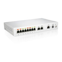
Mx8A/Mx8G17
-
Mx6020
-
Mx60E22
-
Mx120G25
-
Layout28
-
Login29
-
Status32
-
Network32
-
Vlan34
-
System36
-
Sip38
-
Tls&Srtp41
-
Mgcp42
-
Foip44
-
Alarm46
-
Line47
-
Phone Number47
-
Trunk55
-
Phone Number55
-
Routing60
-
Digit Map60
-
System67
-
Media Stream72
-
Greeting78
-
Security85
-
Access List86
-
IP Table93
-
Encryption94
-
Status96
-
Call Status96
-
Logs98
-
Call Message99
-
System Startup100
-
Manage Log100
-
Tools102
-
Upgrade102
-
IP Capture105
-
Reboot106
-
Logout106
-
Lldp108
-
Dhcp111
-
Single VLAN113
New Rock Technologies MX8A Series User Manual (112 pages)
MX Series Voice Gateway
Brand: New Rock Technologies
|
Category: Gateway
|
Size: 3 MB
Table of Contents
-
1 Overview
10 -
-
-
-
Single VLAN101
-
Advertisement

New Rock Technologies MX8A Series User Manual (94 pages)
Voice Gateway
Brand: New Rock Technologies
|
Category: Gateway
|
Size: 2 MB
Table of Contents
-
Contents
3 -
-