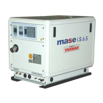
Mase I.S. 6.5 Workshop Manual
Silent diesel generators
Hide thumbs
Also See for I.S. 6.5:
- Use, maintenance and installation manual (98 pages) ,
- Installation manual (48 pages)

Related Manuals for Mase I.S. 6.5


Summary of Contents for Mase I.S. 6.5
- Page 1 I.S. 6.5 50 Hz I.S. 7.6 60 Hz MANUALE OFFICINA WORKSHOP MANUAL cod.42073 REV.1 A.A. 08-01-02...
-
Page 2: Table Of Contents
IS 6.5 - 7.6 Indice Index Identificazione della macchina ....5 Machine identification......5 Composizione dei gruppi elettrogeni ... 5 Generators composition ......5 TABELLA ATTREZZI ........9 TOOL TABLE .......... 9 ALTERNATORE ........13 ALTERNATOR ........13 Statore ............15 Stator ............ - Page 3 IS 6.5 - 7.6 SMONTAGGIO ......... 91 DISASSEMBLY ........91 COPPIE DI SERRAGGIO VITI ....91 SCREW SHUT ........91 Rimozione della cassa ......91 Removing the casing ......91 Rimozione alternatore ......101 Removing the alternator .......101 Rimozione del gruppo scambiatore acqua/aria 103 Removing the water/air exchanger unit 103 Rimozione del coperchio alternatore lato ..
- Page 4 IS 6.5 - 7.6 SERIAL No.
-
Page 5: Identificazione Della Macchina
IS 6.5 - 7.6 1 Identificazione della macchina 1 Machine identification (Fig.1) (Fig.1) 1 - Manufacturer 1 - Costruttore 2 - Machine code 2 - Codice macchina 3 - Year of construction 3 - Anno di costruzione 4 - Fattore di potenza 4 - Power factor 5 - Declared frequency 5 - Frequenza dichiarata... - Page 6 IS 6.5 - 7.6...
- Page 7 IS 6.5 - 7.6 10- Filtro aria motore 10- Engine air filter 11- Vaso di espansione liquido refrigerante 11- Coolant expansion tank 12- Pompa estrazione olio motore 12- Engine oil extraction pump 13- Diesel fuel filter cartridge 13- Cartuccia filtro gasolio 14- Seawater pump 14- Pompa acqua mare 15- Fuel pump...
- Page 8 IS 6.5 - 7.6...
-
Page 9: Tabella Attrezzi
IS 6.5 - 7.6 2 Tabella attrezzi 2 TOOL TABLE Denominazione : Chiave torsiometrica Denomination: Torque spanner Uso : Serve per serrare bulloni e dadi alla Use: To tighten the nuts and bolts to the coppia prescritta prescribed torque Denominazione : Tester batteria Denomination: Battery tester Uso : Controlla lo stato di carica dell’elettrolito Use: To check the electrolyte level of the battery... - Page 10 IS 6.5 - 7.6...
- Page 11 IS 6.5 - 7.6 Denominazione : Tester Denomination: Tester Uso : Misura la tensione AC/DC , le resistenze Use: Measures the AC/DC voltage, the resistors ed i diodi and the diodes Denominazione : Pinza amperometrica Denomination: Amperometric caliper Uso : Misura la tensione AC, frequenza (n° di Use: Measures the AC voltage, frequency giri motore) e corrente AC.
- Page 12 IS 6.5 - 7.6 ALTERNATORE 50 Hz 60 Hz Sincrono, 4-poli, autoeccitato Tipo Aria / acqua ( Intercooler W/A ) Raffreddamento Tensione (V) 115 - 230 120 - 240 Frequenza (Hz) Amps 56,5 - 28,2 66 - 33 Potenza max. (KW) Potenza cont.
-
Page 13: Alternatore
IS 6.5 - 7.6 3 ALTERNATORE 3 ALTERNATOR I generatori della serie IS 6.5/7.6 sono dotati di The generators of the IS 6.5/7.6 series are equipped alternatore senza spazzole, sincrono, a quattro with a brushless, synchronous, 4-pole, self- poli, autoregolato, autoeccitato, con due conden- regulating, self-excited alternator with two satori (fig. - Page 14 IS 6.5 - 7.6...
-
Page 15: Statore
IS 6.5 - 7.6 Stator Statore 3.1.1 Power windings 3.1.1 Avvolgimenti di potenza Features: Caratteristiche: n° Fili Colore/sez n° Wire Color/sez IS 6.5 115/230V 0.388 Ohm 50 Hz 0.388 Ohm IS 6.5 Rosso 6mm 120/240V 0.388 Ohm Red 6mm 50Hz 0.388 Ohm IS 7.6 120/240V... - Page 16 IS 6.5 - 7.6...
-
Page 17: Avvolgimenti Di Eccitazione
IS 6.5 - 7.6 3.1.2 Avvolgimenti di eccitazione 3.1.2 Excitation windings Caratteristiche: Features: n° Fili Colore / sez. n° Wire Color / sez. IS 6.5 115/230V 50-8 2.37 Ohm 50 Hz 50-8 2.37 Ohm IS 6.5 Rosso 1.5mm 120/240V 50-9 2.42 Ohm Read 1.5mm 50Hz... - Page 18 IS 6.5 - 7.6...
-
Page 19: Rotore
IS 6.5 - 7.6 Rotore Rotor 3.2.1 Avvolgimento di rotore (n°2) 3.2.1 Rotor winding (n°2) Caratteristiche: Features: IS 6.5 115/230V 50 Hz IS 6.5 3.70 Ohm 120/240V 50 Hz 3.70 Ohm IS 7.6 120/240V 60 Hz Metodo di controllo: Test method: -Verificare che la resistenza fra le due -Check that the resistance between the two estremità... - Page 20 IS 6.5 - 7.6...
-
Page 21: Diodi Rotore (N°2)
IS 6.5 - 7.6 3.2.2 Rotor diodes (n°2) 3.2.2 Diodi rotore (n°2) Characteristics : SKR 26/16 Caratteristiche : SKR 26/16 Test method: Metodo di controllo: -Disconnect the cables at end A of the 2 diodes -Scollegate i cavi all’estremità A dei 2 diodi (Fig. - Page 22 IS 6.5 - 7.6...
-
Page 23: Condensatori
IS 6.5 - 7.6 Capacitors Condensatori Characteristics - 31.5 mF 450V 50 Hz: Caratteristiche – 31.5 mF 450V 50 Hz: Test method: Metodo di controllo: -Disconnect the 1.5 mm red cables from the -Scollegate i cavi (Rosso 1.5mm ) dai due two capacitors. - Page 24 IS 6.5 - 7.6...
-
Page 25: Motore
IS 6.5 - 7.6 4 Motore 4 Engine 4.1 Caratteristiche tecniche Unità Modello 3 TNE 74 Applicazione Tipo Motore diesel a 4 tempi, verticale, raffreddato ad acqua Speciale camera di precombustione a turbolenza Sistema di combustione (indiretta) N° cilindri - Alesaggio x Corsa 3 - 74 x 78 Materiale blocco cilindri Ghisa... -
Page 26: Manutenzione
IS 6.5 - 7.6 4.2 Manutenzione Per la durata e il corretto funzionamento del generatore è necessario rispettare il programma di controlli e manutenzione indicati nella tabella seguente. L’esecuzione di queste operazioni è descritta, per la parte relativa al motore, sul libretto uso e manutenzione o sul manuale d’officina del costruttore del motore. -
Page 27: Maintenance
IS 6.5 - 7.6 4.2 Maintenance For long life and proper functioning of the generator, the checking and maintenance schedule indicated in the following table must be respected. How to execute these operations is described, for the part relating to the engine, in the use and maintenance handbook or in the workshop manual of the engine manufacturer. -
Page 28: Tavola Guasti
IS 6.5 - 7.6 4.3 Tavola guasti... - Page 29 IS 6.5 - 7.6 4.3 Tavola guasti...
-
Page 30: Trouble-Shooting
IS 6.5 - 7.6 4.3 Trouble-shooting... - Page 31 IS 6.5 - 7.6 4.3 Trouble-shooting...
- Page 32 IS 6.5 - 7.6 Schema impianto dell'impianto d'alimentazione Fuel system diagram Injector High-pressure injection pipe Fuel return pipe Return to tank Injection pump Fuel filter From tank Fuel pump...
-
Page 33: Combustibile
IS 6.5 - 7.6 4.4 Combustibile 4.4 fuel 1. Uso corretto del gasolio 1. Proper use of diesel fuel Usare gasolio di qualità equivalente o superiore a Use diesel fuel of a quality equivalent to or higher quello ISO 8217 DMA, BS 2869 Parte 1 classe A1o than ISO 8217 DMA, BS 2869 Part 1 Class A1 or Parte 2 classe A2. - Page 34 IS 6.5 - 7.6...
-
Page 35: Pompa Gasolio Elettrica
IS 6.5 - 7.6 4.5 Electric diesel fuel pump 4.5 Pompa gasolio elettrica Characteristics : 12V Caratteristiche : 12V Test method: Metodo di controllo: - Check that the filter (Fig.14 Ref.1) is not dirty. - Controllare che il filtro (fig.14 rif.1) non sia -Disconnect the cables. - Page 36 IS 6.5 - 7.6 Schema dell'impianto di lubrificazione Lubrication system diagram Heat exchanger (option) Pressure regulating Injection pump Oil filter (with bypass valve) valve Pressure switch Safety valve Cylinder block main duct Cam shaft bearing Oil pump Main bushing Intermediate gear Oil intake pipe Equalizer Connecting...
-
Page 37: Filtro Gasolio A Bicchiere
IS 6.5 - 7.6 Lubrication 4.7 Lubrificazione 1. Proper use of engine oil 1. Uso corretto dell’olio lubrificante Proper use of engine oil guarantees: Un corretto uso dell’olio lubrificante garantisce: (1) Adequate protection of the engine parts (1) L’adeguata protezione delle parti del motore subject to friction against engine friction and sottoposte ad attrito contro l’attrito stesso e wear. - Page 38 IS 6.5 - 7.6...
-
Page 39: Sensori
IS 6.5 - 7.6 5 Sensors 5 Sensori 5.1 Thermostatic valve 5.1 Valvola termostatica Test method: Metodo di controllo - Unscrew the water inlet cover from the engine - Svitare il coperchio ingresso acqua dalla sede seat and extract the thermostat. del motore, estrarre il termostato. - Page 40 IS 6.5 - 7.6...
-
Page 41: Termointerruttore Motore A Circuito Chiuso
IS 6.5 - 7.6 5.2 Closed-circuit engine thermal switch 5.2 Termointerruttore motore a circuito chiuso Characteristics: 120° C N.O. contact. Caratteristiche: 120° C contatto n.o. Test method Metodo di controllo - Immerse the thermostat in a container of antifreeze - Immergere il termostato in un contenitore di fluid or oil. - Page 42 IS 6.5 - 7.6...
-
Page 43: Sensore Temperatura
IS 6.5 - 7.6 5.3 Temperature sensor 5.3 Sensore temperatura Characteristics: 0-24V 0-120° C Caratteristiche: 0-24V 0-120° C Test method Metodo di controllo - Disconnect the cable - Scollegare il cavo di cablaggio - Check that there is about 785 Ohm at a - Verificare che fra il terminale e massa ci siano temperature of 20°... - Page 44 IS 6.5 - 7.6...
-
Page 45: Termostato Motore A Circuito Aperto (Mare)45
IS 6.5 - 7.6 5.4 Termostato motore a circuito aperto (mare) 5.4 Open-circuit engine thermostat (sea) Caratteristiche: 70°C contatto n.o. Characteristics: 70°C N.O. contact Metodo di controllo Test method - Immergere il termostato in un contenitore di - Immerse the thermostat in a container of water. acqua. - Page 46 IS 6.5 - 7.6...
-
Page 47: Pressostato Olio
IS 6.5 - 7.6 5.5 Pressostato olio 5.5 Oil pressure switch Caratteristiche: contatto n.c. motore fermo Characteristics: contatto n.o. motore in marcia n.c.= normally closed (motore in stopped) n.o.= normally open (motore in run) Metodo di controllo: Test method: -Mettere in marcia il motore . -Start the engine. - Page 48 IS 6.5 - 7.6...
-
Page 49: Sensore Pressione Olio
IS 6.5 - 7.6 5.6 Oil pressure sensor 5.6 Sensore pressione olio Characteristics: 6-24V 0-5 bar Caratteristiche: 6-24V 0-5 bar Test method: Metodo di controllo: - Disconnect the cable - Scollegare il cavo di cablaggio - Check that there is about 10 Ohm at ambient - Verificare che fra il terminale e la carcassa vi pressure between the terminal and the casing siano circa 10 Ohm a pressione ambiente... - Page 50 IS 6.5 - 7.6 Schema dell'impianto di raffreddamento a circuito chiuso/acqua mare Closed-circuit/seawater cooling system diagram ACQUA MARE CIRCUITO CHIUSO CLOSED CIRCUIT SEA WATER COLLETTORE SCARICO MIX GAS EXHAUST SCARICO COMBUSTI MANIFOLD A MARE SEA EXHAUST BURNT GAS MIX TESTA CILINDRO TERMOSTATO CYLINDER HEAD THERMOSTAT...
-
Page 51: Raffreddamento
IS 6.5 - 7.6 6 RAFFREDDAMENTO 6 SEA WATER COOLING Impianto "acqua mare/circuito chiuso Seawater/closed-circuit system Caratteristiche: circuito chiuso con liquido Characteristics: closed circuit with open-circuit circuito aperto con acqua di mare. liquid with seawater. Portata pompa acqua mare 25 lt./min. Seawater pump flow rate 25 l/min. - Page 52 IS 6.5 - 7.6...
-
Page 53: Pompa Acqua
IS 6.5 - 7.6 Water pump 6.2 Pompa acqua Characteristics:type Johnson (F4B-8) Caratteristiche: tipo Johnson (F4B-8) Test method: Metodo di controllo: -Visual -Visivo -Remove the screws (Fig.23 Ref.1) and remove -Togliere le viti (fig.23 rif.1) e rimuovere il the pump cover (Fig.23 Ref.2). coperchio pompa (fig.23 rif.2). - Page 54 IS 6.5 - 7.6...
-
Page 55: Cinghia Pompa Acqua
IS 6.5 - 7.6 6.3 Water pump belt 6.3 Cinghia pompa acqua Test method: Metodo di controllo: -Press on the belt with about 10 kg and check -Premere con circa 10Kg sulla cinghia, that flexure does not exceed 0.5cm (Fig.24 verificare che la flessione non superi 0,5cm Ref.1). - Page 56 IS 6.5 - 7.6...
-
Page 57: Scambiatore Di Calore Acqua/Acqua
IS 6.5 - 7.6 6.4 Water/water heat exchanger 6.4 Scambiatore di calore acqua/acqua 1. Proper use of the closed-circuit cooling 1. Uso corretto dell’acqua di water raffreddamento a circuito chiuso The impurities contained in the cooling water deposit impurità contenute nell’acqua in the engine and in the exchanger in the form of raffreddamento si depositano nel motore e nello... - Page 58 IS 6.5 - 7.6...
-
Page 59: Scambiatore Di Calore Acqua/Aria
IS 6.5 - 7.6 6.5 Water/air heat exchanger 6.5 Scambiatore di calore acqua/aria Characteristics: tube bundle / radiant mass Caratteristiche: fascio tubiero / massa radian- Test method Metodo di controllo - Check that there is no sedimentation or foreign - Controllare che all'interno dei tubi (fig.26) non bodies in the tubes (Fig.26) . - Page 60 IS 6.5 - 7.6...
-
Page 61: Regolazioni
IS 6.5 - 7.6 7 REGOLAZIONI 7 ADJUSTMENTS 7.1 Regolazione dei giri 7.1 Rpm adjustment Poiche’ l' alternatore è del tipo a quattro poli vale Since the alternator is type four-pole the la seguente corrispondenza: following correspondence is valid: giri/min. 1500 1500 1800... - Page 62 IS 6.5 - 7.6...
-
Page 63: Regolazione Serrature E Maniglie
IS 6.5 - 7.6 Regolazione serrature e maniglie Lock and handle adjustment Metodo di controllo: Test method: - Verificare che gli sportelli si chiudano in modo - Check that the doors close properly and do not corretto senza troppa mobilità nei confronti della move excessively against the casing. - Page 64 IS 6.5 - 7.6...
-
Page 65: Impianto Elettrico
IS 6.5 - 7.6 8 ELECTRICAL SYSTEM 8 IMPIANTO ELETTRICO 8.1 Instrument panel 8.1 Cruscotto Each generator is fitted with an instrument panel Ogni gruppo elettrogeno dispone di un pannello for the controls. strumenti per i comandi e i controlli. This is the control centre for the generator, the 12V Questo è... - Page 66 IS 6.5 - 7.6...
-
Page 67: Pannelli Strumenti A Distanza
IS 6.5 - 7.6 8.2 Remote instrument panels 8.2 Pannelli strumenti a distanza Each generator is fitted with a remote instrument Ogni gruppo elettrogeno dispone di un pannello panel for the controls with the following components: strumenti a distanza per i comandi e i controlli sui quali si trovano i seguenti componenti: 1 - Water temperature thermometer 2 - Oil pressure switch... - Page 68 IS 6.5 - 7.6...
-
Page 69: Pulsante Start / Stop-Preriscaldo
IS 6.5 - 7.6 8.2.3 - START/STOP Preheating button 8.2.3 Pulsante START / STOP-Preriscaldo Characteristics: 12V 4-pole Caratteristiche: 12V 4poli Test method Metodo di prova -Disconnect the cables -Scollegare i cavi di cablaggio - With the tester check the continuities as per - Verificare con il tester le continuità... - Page 70 IS 6.5 - 7.6...
-
Page 71: Fusibili Candelette
IS 6.5 - 7.6 8.3 Glow plug fuses 8.3 Fusibili candelette Characteristics: 20A, lamellar, yellow, 2 pieces Caratteristiche: 20A lamellare giallo 2 pezzi Test method: Metodo di controllo: - Detach the 2 fuses - Staccare i 2 fusibili - Check that the protection blade is intact - Verificare che la lamella di protezione sia - Or check that there is continuity integra... - Page 72 IS 6.5 - 7.6...
-
Page 73: Contaore
IS 6.5 - 7.6 8.5 Hour counter 8.5 Contaore Characteristics: 115V DC, 50 or 60 Hz Caratteristiche: 115V dc 50 o 60 Hz - Check that the hour counter marks the time - Verificare che a generatore in moto, il when the generator is running. - Page 74 IS 6.5 - 7.6...
-
Page 75: Termico Linea 12V
IS 6.5 - 7.6 12V line thermal switch Termico linea 12V Characteristics: 1-pole 12A Caratteristiche: 1polo 12A Test method Metodo di controllo - check that the pin is not positioned towards the - Verificare che il cilindretto non sia posizionato outside;... - Page 76 IS 6.5 - 7.6...
-
Page 77: Cablaggio Motore
IS 6.5 - 7.6 Engine wiring Cablaggio motore -Check that the cables and the junctions are not -Controllare che i cavi e le giunzioni non siano oxidised or peeled. ossidati o spellati. - BY 255 diode - Diodo BY 255 Test method: Metodo di prova: - Detach the connector of the electromagnet and... - Page 78 IS 6.5 - 7.6 Schema di principio Operating principle diagram...
-
Page 79: Modulo Protezione Motore
IS 6.5 - 7.6 Modulo Protezione Motore Engine Protection Module Caratteristiche: controllore motore 12V MASE Characteristics: 12V MASE engine controller Metodo di controllo Test method - Verificare il fusibile F1 (fig. 39) 6.3A 5x20 - Check the fuse F1 (Fig. 39) 6.3A 5x20... - Page 80 IS 6.5 - 7.6 rosso 1.5mm red 1.5mm verde 1.5mm rosso 6mm green 1.5mm red 6 mm +batt...
-
Page 81: Alternatore Carica Batteria
IS 6.5 - 7.6 8.10 Alternatore carica batteria 8.10 Battery charger alternator Caratteristiche: 12 V 40A Characteristics: 12 V 40A Metodo di controllo: Test method: - Verificare che la spia di batteria sul modulo - Check that the battery light on the engine protection module is off when the generator is running. - Page 82 IS 6.5 - 7.6...
-
Page 83: Elettromagnete Motore
IS 6.5 - 7.6 8.11 Elettromagnete motore 8.11Engine electromagnet Caratteristiche:12V DC Characteristics:12V DC Resistors Resistenze Black-white ~0.332 Ohm Nero-Bianco ~0.332 Ohm Black-red ~23.3 Ohm Nero-Rosso ~23.3 Ohm Black-ground= Nero-Massa= Metodo di controllo: Test method: -Scollegate il connettore dell’elettromagnete -Detach the electromagnet connector -Verificate che le resistenze rientrino nei valori -Check that the resistors fall within the table di tabella. - Page 84 IS 6.5 - 7.6...
-
Page 85: Candelette Pre-Riscaldo 3 Pezzi
IS 6.5 - 7.6 8.12 Pre-heating glow plugs, 3 pieces 8.12 Candelette pre-riscaldo 3 pezzi Characteristics: 12V 12A Caratteristiche: 12V 12A Test method: Metodo di controllo: - Disconnect the two 2.5 mm² white wires and - Scollegate i 2 fili bianchi 2.5 mm² di cablaggio the cable which jumpers 2 of the 3 glow plugs. - Page 86 IS 6.5 - 7.6...
-
Page 87: Motorino Avviamento
IS 6.5 - 7.6 8.13 Starter motor 8.13 Motorino avviamento Characteristics:12V 0.8 KW Caratteristiche:12V 0,8 KW Test method: Metodo di controllo: -Disconnect the 2.5mm white cable. (with female -Scollegare il cavo di cablaggio bianco Faston) sez.2.5mm . (con faston femmina) -Use a 12V battery connecting the (+) of the battery -Utilizzare una batteria 12V collegando il (+) della to the screw terminal and the (-) to the ground... - Page 88 IS 6.5 - 7.6 Terminal Cover Cathode plate Separator Battery body Felt Anode plate Grease Acceptable Insufficient Excessive Maximum level Minimum Fluid level level Battery tester Measuring the battery charge with the tester...
-
Page 89: Batteria
IS 6.5 - 7.6 8.14 Battery 8.14 Batteria Characteristics: Least capacity 70 Ah, 12V Caratteristiche: Capacità minima 70 Ah, 12V Test method: Metodo di controllo: (1) Electrolyte level (1) Livello dell’elettrolito Check the electrolyte level in each cell. If insufficient, Controllare il livello dell’elettrolito in ogni cella. - Page 90 IS 6.5 - 7.6...
-
Page 91: Smontaggio 91
IS 6.5 - 7.6 9 DISASSEMBLY 9 SMONTAGGIO 9.1 Removing the casing 9.1 Rimozione della cassa - Remove the side doors and the top panel - Rimuovere gli sportelli laterali ed il pannello superiore COPPIE DI SERRAGGIO VITI SCREW SHUT Componente Diametro filettatura x passo Coppie di serraggio (Nm) - Page 92 IS 6.5 - 7.6...
- Page 93 IS 6.5 - 7.6 - Unscrew the anchor screws and remove the - Svitare le viti di ancoraggio e rimuovere i pan- panels (Fig.46 Ref.1/2). nelli (fig.46 rif.1/2).
- Page 94 IS 6.5 - 7.6...
- Page 95 IS 6.5 - 7.6 - Sconnettere il connettore (fig.47 rif.1). - Detach the connector (Fig.47 Ref.1). - Svitare le vite del pannello (fig.47 rif.2). - Unscrew the panel screws (Fig.47 Ref.2). - Sconnettere i cavi (fig.47 rif.3). - Disconnect the cables (Fig.47 Ref.3). - Rimuovere il sottocruscotto (fig.47 rif.4).
- Page 96 IS 6.5 - 7.6...
- Page 97 IS 6.5 - 7.6 - Remove the nuts (Fig.48 Ref.1) - Rimuovere i dadi (fig.48 rif.1) - With the aid of a rubber hammer, remove the - Con l'ausilio di un martello in gomma, sfilare le side frames (Fig.48 Ref.2) cornici laterali (fig.48 rif.2)
- Page 98 IS 6.5 - 7.6...
- Page 99 IS 6.5 - 7.6 - Rimuovere le cornici (fig.49 rif.1-2) - Remove the frames (Fig.49 Ref.1-2) - Svitare le viti (fig.49 rif.3) e rimuovere le - Undo the screws (Fig.49 Ref.3) and remove fiancate (fig.49 rif.4). the sides (Fig.49 ref.4).
- Page 100 IS 6.5 - 7.6...
-
Page 101: Removing The Alternator
IS 6.5 - 7.6 9.2 Removing the alternator 9.2 Rimozione alternatore -Remove the 6 screws (Fig.50 Ref.1)of the -Rimuovere le 6 viti (fig.50 rif.1)del coperchio alternator cover (Fig.50 Ref.2) alternatore (fig.50 rif.2) -Disconnect the cables from the component -Scollegare tutti i cavi dalla base supporto com- support base (Fig.50 Ref.3) ponenti (fig.50 rif.3) -Remove the retaining screws and the base... - Page 102 IS 6.5 - 7.6...
-
Page 103: Removing The Water/Air Exchanger Unit
IS 6.5 - 7.6 9.3 Removing the water/air exchanger unit 9.3 Rimozione del gruppo scambiatore (Fig.51 Ref.1) and engine combustion air acqua/aria (fig.51 rif.1) e filtro aria combustio- filter(Fig.51 Ref.3) ne motore(fig.51 rif.3) - Remove the retaining screws of the exchanger - Rimuovere le viti di fissaggio dello scambiatore (Fig.51 Ref.2) (fig.51 rif.2) - Page 104 IS 6.5 - 7.6...
-
Page 105: Removing The Alternator Cover On The Bearing S
IS 6.5 - 7.6 Removing the alternator cover on the Rimozione del coperchio alternatore bearing side (Fig.52 Ref.1) lato cuscinetto (fig.52 rif.1) - Remove the retaining screws of the alternator - Rimuovere le viti di fissaggio del coperchio cover on the bearing side (Fig.52 Ref.2) alternatore lato cuscinetto (fig.52 rif.2) - With the aid of an extractor, remove the cover - Con l'ausilio di un estrattore, sfilare il coperchio... - Page 106 IS 6.5 - 7.6...
- Page 107 IS 6.5 - 7.6 Removing the stator (Fig.53 Ref.1) Rimozione dello statore (fig.53 rif.1) - With two screwdrivers prise in the position - Fare leva con due cacciaviti nella posizione indicated in Fig.53 Ref.2. indicata da fig.53 rif.2. - Remove the stator, taking care not to damage - Rimuovere lo statore, facendo attenzione a non the rotor windings.
- Page 108 IS 6.5 - 7.6...
-
Page 109: Removing The Rotor Bearing
IS 6.5 - 7.6 Removing the rotor (Fig.54 Ref.1) Rimozione del rotore (fig.54 rif.1) - Remove the anchor screws (Fig.54 Ref.2) - Rimuovere le viti di ancoraggio (fig.54 rif.2) - Remove the fan and the rotor from the flywheel - Sfilare la ventola ed il rotore dalla sede volano housing. - Page 110 IS 6.5 - 7.6...
-
Page 111: Motore
IS 6.5 - 7.6 MOTORE ENGINE Rif. Cod. Q.ty DESCRIZIONE DESCRIPTION 81132 MOTORE YANMAR 3TNE74A-MG - ENGINE YANMAR 3TNE74A-MG - IS6.5 IS6.5 81133 MOTORE YANMAR 3TNE74A-MG 60Hz EPA - IS7.6 ENGINE YANMAR 3TNE74A-MG 60Hz EPA - IS7.6 62372 STAFFA FISSAGGIO GRUPPO BRACKET 62379 STAFFA SX SUPPORTO MOTORE... - Page 112 IS 6.5 - 7.6...
-
Page 113: Alternatore
IS 6.5 - 7.6 ALTERNATORE ALTERNATOR Rif. Cod. Q.ty DESCRIZIONE DESCRIPTION 011319 ALTERNATORE IS 6.5/7.6 50/60HZ ALTERNATOR IS 6.5/7.6 50/60HZ 011321 VENTOLA 011324 COPERCHIO LATO MOTORE COVER MOTOR SIDE 011479 GRIGLIA PROTEZIONE ALTERNATORE ALTERNATOR PROTECTION SCREEN 011218 FASCIA PROTEZIONE ALTERNATORE ALTERNATOR PROTECTION BAND 910315 STATORE... - Page 114 IS 6.5 - 7.6...
-
Page 115: Cassa
IS 6.5 - 7.6 FRAME CASSA Rif. Cod. Q.ty DESCRIZIONE DESCRIPTION KIT CASSA INSONORIZZATA SOUNDPROOFING BOX KIT 011233 PANNELLO FISSO ALTERNATORE ALTERNATOR FIX PANEL 011235 PANNELLO FISSO MOTORE ENGINE FIX PANEL 011237 SPORTELLO LATERALE LATERAL DOOR 011239 SPORTELLO SUPERIORE UPPER DOOR 011241 CHIUSURA DX FONDO BOTTOM RH CLOSURE... - Page 116 IS 6.5 - 7.6...
-
Page 117: Marenizzazione
IS 6.5 - 7.6 MARENIZZAZIONE SEA WATER Rif. Cod. Q.ty DESCRIZIONE DESCRIPTION GRUPPO MARINIZZAZIONE MARINIZED SET 62394 SCAMBIATORE ACQUA/ACQUA WATER/WATER EXCHANGER 011228 STAFFA SUPPORTO SCAMBIATORE EXCHANGER SUPPORT BRACKET 10814 GOMITO A 90° M/F 3/8" ELBOW 10614 PORTAGOMMA D.15 3/8 NIPPLE 70198 mt.0,3 TUBO CARBURANTE D.10X17... - Page 118 IS 6.5 - 7.6...
-
Page 119: Pannello Comandi
IS 6.5 - 7.6 PANNELLO COMANDI CONTROL PANEL IS 6.5 Rif. Cod. Qty. Descrizione Description 011220 QUADRO DI COMANDO IS 6.5 50.115/230 CONTROL PANEL 012398 PANNELLO STRUMENTI PANEL 32393 MODULO PROTEZIONE MOTORE EMGINE PROTECTION MODULE 32402 INTERRUTTORE START/0/STOP START/0/STOP BUTTON 30270 CALOTTA PER T11-211 TIPO H THERMAL SWITCH PROTECTION... - Page 120 IS 6.5 - 7.6...
-
Page 121: Wiring Diagram
IS 6.5 - 7.6 WIRING DIAGRAM ESQUEMA ELECTRICO... - Page 122 IS 6.5 - 7.6 REFERENCIAS ESQUEMA ELECTRICO WIRING DIAGRAM REFERENCES 1 – Cuentahoras 1 - Hours counter 2 – Interruptor magnetotérmico 2 - Magnetothermal switch 3 – Aisladores 3 - Isolator 4 – Tablero de bornes de potencia 4 - Power terminal board 5 –...
-
Page 123: Versioni Speciali
IS 6.5 - 7.6 VERSIONI SPECIALI SPECIAL VERSION... -
Page 124: Is 7.6 Cod.001351
IS 7.6 cod.001351 Sono riportate in questo CAPITOLO, gli alle- gati delle versioni speciali Linea IS 6.5 - 7.6. Potrete trovare i componenti e gli schemi elettrici non presenti nella versione standard. Cod 001351 IS 7.6s M60.120 CSCV NA Descrizione: La macchina si differisce per il Remote control che ha in più... - Page 125 IS 7.6 cod.001351 3) Spia cumulativo allarmi (Fig.61 rif. 34) Caratteristiche: lampada 12V Metodo di controllo: -Accendere il generatore e fare intervenire un allarme (es. mettere a massa il filo del pressostato olio) -Controllate l’accensione della relativa spia sul modulo protezione motore. -Verificare con starter la presenza della tensio- ne di batteria fra i pin 7 e il pin 4 del connettore a 9 poli, la spia deve risultare accesa.
- Page 126 IS 7.6 cod.001351...
- Page 127 IS 7.6 cod.001351...
- Page 128 IS 7.6 cod.001351 RIFERIMENTI PER LO SCHEMA ELETTRICO WIRING DIAGRAM REFERENCES Contaore 1 - Hours counter Interruttore magnetotermico 2 - Magnetothermal switch Isolatore 3 - Isolator Morsettiera di potenza 4 - Power terminal board Condensatore 5 - Capacitors Statore 6 - Stator Rotore 7 - Rotor Alternatore...
- Page 129 IS 7.6 cod.001351 RICAMBI IS 7.6 cod.001351 SPARE PARTS IS 7.6 cod.001351...
- Page 130 IS 7.6 cod.001351...
- Page 131 IS 7.6 cod.001351 Rif. Cod. Q.ty Descrizione Description 014102 PANNELLO STRUMENTI IS 7.6 COMPLETO COMPLETE CONTROL PANEL 011222 PANNELLO STRUMENTI BIANCO WHITE CONTROL PANEL 41651 ADESIVO LABEL 30270 CALOTTA PER T11-211 TIPO H THERMAL SWITCH PROTECTION 30475 CONTAORE 110V 60HZ HOURSMETER 60Hz 31029 MICRODISG.TERM.T11-211 12A...
Need help?
Do you have a question about the I.S. 6.5 and is the answer not in the manual?
Questions and answers