
Related Manuals for Mase IS 9.6 B


Summary of Contents for Mase IS 9.6 B
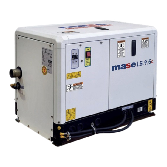
- Page 1 MANUALE USO, MANUTENZIONE E INSTALLAZIONE USE, MAINTENANCE AND INSTALLATION MANUAL IS 9.6 Rev.0 A.A. 17/02/2015 cod.43375 Tipo modello N° matricola Codice...
- Page 2 Thank you for having chosen a product MASE. As a leading generator manufacturer, Mase Generators offers a wide range of generators with an output from 1 KVA portable generators to 1600 KVA units for special applications.
-
Page 3: Table Of Contents
IS 9.6 CONTENTS DEFINITIONS USED ..........5 MAINTENANCE ..........34 6.1 Preamble ............34 PRELIMINARY PRESCRIPTIONS ......7 6.2 Routine engine maintenance ......34 6.3 Engine oil check ..........34 GENERAL INFORMATIONS ......6 6.4 Engine oil change ..........35 6.5 Oil filter ............ -
Page 4: Definitions Used
A person able to evaluate the job assigned to him and recognise the possible dangers on the basis of training at the MASE training centres, with professional experience and knowledge of the equipment in question and of the possible dangers deriving in the event of negligent behaviour. - Page 5 IS 9.6 - Connection in bad state The live parts are not fully covered with insulation removable by destruction only, the connections are not secure because of unstable tightening of the parts and a development of oxide between the parts. - Direct contact Contact of persons or animals with live parts.
-
Page 6: Preliminary Prescriptions
Ongoing improvement and development of the product may have led to modifications to the generator which are not included in this publication. Whenever a problem concerning the generator or this publication arises, consult with Mase Generators SPA for the latest information available. -
Page 7: General Informations
The limits of use are: - operating temperature: -10° +40° - relative humidity: 30% - 90% - the generator is suitable for marine operation. mase mase Installations are subject to approval by or by an installer authorised by Arbitrary modifications to the machine are prohibited for safety reasons. -
Page 8: Safety Symbols
IS 9.6 SAFETY INSTRUCTIONS The electromechanics equipments, included the generating sets, switch, command electric equipments and accessories, can cause damages to people and,if they are installed, used or mainteined with not qualified operations, they can put in serious danger the life of people. To avoid accidents is necessary to know the potential risks and operate with caution.Read and follow all the precautions and the instructions for the safety. -
Page 9: Symbols On The Generator Group
IS 9.6 1.4 S YMBOLS ON THE GENERATOR GROUP - 10... -
Page 10: Safety Label Informations
• These labels warn the user of any danger which may cause serious injury. Carefully read the meaning and the precautions described in this manual. • If the label detaches or becomes illegible, replace it with a new one which can be requested from an authorised mase dealer. Danger Symbols... - Page 11 IS 9.6 Danger Symbols Meaning PREVENTING FIRE Can cause severe injury or death. • Start • Start the engine only from a starter switch without any load or in neutral posi- tion of the clutch of machine unit. The machine unit suddenly starts to move or generates power to cause serious personal injury.
- Page 12 IS 9.6 Danger Symbols Meaning EXHAUST SYSTEM Carbon monoxide. Group generator use. Carbon monoxide can cause severe nausea, fainting, or death. Carbon monoxide is an odorless, colorless,tasteless, non irritating gas,able to, if inhaled only also for brief time to provoke the death. Be especially careful if operating the generator set when moored or anchored under calm conditions as gases may accumulate.
- Page 13 IS 9.6 Danger Symbols Meaning BATTERY Do not touch the electrolitic battery acid Sufficient ventilation of the battery area. • Keep the area around the battery well ventilated, paying attention to keep sparks, open flame and any other form of ignition away. During engine running or charging battery, hydrogen gas is produced from the battery and can be easily ignited.
-
Page 14: Reference Documents
Instruction manual for use and maintenance of 1.9 I DENTIFICATION OF THE GENERATOR UNIT the generators,(this manual). Engine use and maintenance manual. 1 - Machine name mase 2 - Machine code List of Service Centres. 3 - Serial number mase Warranty certificate. -
Page 15: General Characteristics
IS 9.6 2 GENERAL CHARACTERISTICS The generators have been designed for use in the marine field, using highly reliable 1500/1800 rpm air/ water-cooled diesel engines. Particular attention has been paid to the degree of protection against external agents, engine protection and protection of the electrical parts against overload or overheating, adopting automatic systems able to stop the generator in the event of malfunctioning. -
Page 16: Command And Control Panel
IS 9.6 2.2 R EMOTE COMMAND AND CONTROL PANEL STANDARD VERSION Each generator is fitted with an instrument panel for commands and controls with the following components: 1) START BUTTON 2) STOP BUTTON 3) MENU NAVIGATION BUTTON 4) MENU NAVIGATION BUTTON 5) MENU SELECTION BUTTON 6) DISPLAY - 17... -
Page 17: Table Of Technical Characteristics
IS 9.6 2.3 T ECHNICAL CHARACTERISTICS TABLE IS 9.6 MODEL GENERAL FEATURES MAX POWER (LTP) CONTINUOUS POWER (PRP) POWER FACTOR (Cos Φ) RATED VOLTAGE 120 - 240 RATED FREQUENCY GRADE OF PROTECTION IP 23 MAX TEMP. OF USE °C - °F 40 - 104 MIN TEMP. -
Page 18: Installation
IS 9.6 - The generator must be positioned in such a way as to 3 INSTALLATION facilitate normal maintenance operations. - It is advisable to install the generator in the propulsion engine room provided that it meets the The generator may only be installed by qualified above conditions. -
Page 19: Lifting
Two water intake systems are normally adopted on boats: -Direct intake system (ref.4). -System with baffle (ref.5). mase recommends using the direct intake system (ref.3), since it prevents intake of pressurised water into the intake ducts, instead generating a vacuum easily overcome by the water pump head of the generator. -
Page 20: 2Components
IS 9.6 3.5.2 C OMPONENTS If the generator is installed at a height over 1m (3,3ft) above the waterline, a check valve (ref.2) must be fitted after the seawater intake to prevent the water circuit from emptying out when the engine is off. If the circuit is empty, the water pump impeller may be damaged during starting. -
Page 21: 3Typical Installations
IS 9.6 3.5.3 T YPICAL NSTALLATIONS YPICAL INSTALLATION WITH GENERATOR ABOVE THE WATERLINE YPICAL INSTALLATION WITH GENERATOR UNDER THE WATERLINE - 22... - Page 22 IS 9.6 mase YPICAL INSTALLATION WITH GENERATOR ABOVE THE WATERLINE WITH WATER GAS SEPARATOR mase YPICAL INSTALLATION WITH GENERATOR UNDER THE WATERLINE WITH WATER GAS SEPARATOR - 23...
- Page 23 IS 9.6 YPICAL INSTALLATION WITH GENERATOR ABOVE THE WATERLINE WITH GENSEP WATER GAS SEPARATOR YPICAL INSTALLATION WITH GENERATOR UNDER THE WATERLINE WITH GENSEP WATER GAS SEPARATOR - 24...
-
Page 24: 5Exhaust System
IS 9.6 3.5.5 E XHAUST SYSTEM The generator combustion gas/water exhaust system Muffler must be independent of that of the main engines (see installation diagrams). The pipe length from the highest point of the exhaust pipe to the exhaust must not exceed 2 m. This is to prevent that when the generator is switched off, the water that is left in the exhaust pipe flows back to the engine after having filled the... -
Page 25: Fuel Circuit
IS 9.6 3.6 F IRCUIT The generator is diesel-powered by means of the unions marked "DIESEL FUEL INLET" (rif.1) e "DIESEL FUEL OUTLET" (rif.2). The latter serves to return excess fuel. The fuel pipes must be in hydrocarbon-resistant rubber with an inside diameter of 8mm (0.31in). For differences in level of more than 500mm (19.6in), fit a single-acting check valve in order to prevent the fuel system from emptying out. -
Page 26: Electrical Connections
CONTROL PANEL CONNECTION The generator can be connected with a connector (ref.3) to the remote starting panel(with 20 meters [80 inch] of cable), supplied by mase as an optional, and can be installed on the dashboard. Secure the cable to the plastic support (ref.4) using hose clamps. -
Page 27: C. Connection
IS 9.6 The control panel must necessarily be installed as it is essential for generator operation. Do not use devices different from the control provided with the generator, since they may be incompatible with the generator. Make the connection with the battery detached. The control panel is supplied with a 10 m long connection cable. -
Page 28: 4Generator-Network Switching
IS 9.6 - Make sure that the sum of the generator loads doesn't overcome the nominal power of the generator group. - Despite the group is provided with a thermal switch (rif.1), it's recommend to interpose magnetothermal protections or similar between generator and electric users, according to the following table. -
Page 29: Using The Generator
IS 9.6 4 USING THE GENERATOR 4.1 P RELIMINARY HECKS Before beginning with any starting procedures, it is extremely important to “familiarise” yourself with the generator and its controls. Furthermore, visually inspect the generator and the installation. Any source of real or potential risk must be eliminated before proceeding. -
Page 30: Starting The Generator
Before starting the generator ensure that all the preliminary checks have been carried out. Start Press the ON/OFF pushbutton (ref.1) to turn on the module. It will show “mase” logo on display. Press and hold pressed the START pushbutton (ref.2) in order to preheat the glow plugs (pre-starting) and then start the engine. -
Page 31: Safety Switches And Warning Signals
IS 9.6 5 SAFETY SWITCHES AND WARNING SIGNALS The generators are equipped with a set of safety switches which protect it against improper use and problems which may jeopardise its integrity. 5.1 P ROTECTION AGAINST SHORT CIRCUITS AND OVERLOAD The generator is protected against short-circuits and electrical overload. -
Page 32: Control Panel - Alarm Codes
IS 9.6 5.3 E NGINE PROTECTION MODULE CBU device (Can-Bus transmission unit) controls and driving the genset. Large display and the control push-buttons allow an easy use and monitoring of the CBU unit. Displayed information - Voltage Vac - Frequency Hz - Hourmeter - Battery voltage of the genset - Voltage of onboard batteries... -
Page 33: Maintenance
IS 9.6 provided by the engine manufacturer, which is provided with each generator. 6 MAINTENANCE 6.3 E 6.1 P NGINE HECK REAMBLE It is recommended to strictly follow the instructions - Check the oil level by means of the cap/dipstick (ref.1). in the manual provided by the engine manufacturer, The oil level must always be between the MAX and MIN which accompanies each generator. -
Page 34: Engine Oil Change
IS 9.6 6.4 E NGINE OIL CHANGE Use diesel engine oil Top up the engine oil through the hole (ref.1). To change the oil in the engine oil sump, take out the dipstick (ref.2). Suct exhaust oil with a manual pump (ref.3). It is advisable to drain the oil when it is still sufficiently warm so that it flows easily. -
Page 35: Replacing / Cleaning The Fuel Pump Filter
IS 9.6 6.6 R EPLACING LEANING ILTER This operation is carried out following the steps below: - Remove the pipe (ref.1) - Slide out the filter (ref.2) - Clean or replace it For reassembly repeat the operations in reverse order. After replacing the filter, the fuel system has to be bled by carrying out the operations described in paragraph 6.8. -
Page 36: Draining The Cooling System
IS 9.6 6.10 DRAINING THE COOLING SYSTEM In order to carry out maintenance on the water/air Genset exchanger or the cooling system, the seawater intake circuit must be drained. Carry out this operation as follows: - Close the seawater intake cock (ref.1). Discarge - Open the drain tap (ref.2) until all the water has drained out. -
Page 37: Seawater Pump Maintenance
IS 9.6 6.12 S EAWATER PUMP MAINTENANCE At least once a year check the integrity of the rubber seawater pump impeller. Before opening the seawater pump to inspect the impeller, drain the seawater from the cooling system as described in paragraph 6.10. To access the impeller, remove the cover (ref.5) and use pliers to extract the impeller (ref.6), pulling it hard towards the outside. -
Page 38: Alternator Maintenance
IS 9.6 6.14 ALTERNATOR MAINTENANCE The alternator used on this model generator is type synchronous, self-excited. This type of brushless alternator without manifold does not require any particular maintenance. Periodic inspections and maintenance are limited to eliminating any traces of moisture and oxidation which may damage it. -
Page 39: List Of Recommended Spare Parts
HECKING REPLACING THE ALTERNATOR V BELT A kit with recommended spare parts is available and may be ordered from the Mase Service Network or Technical Service. 6.17 P ERIODS OF INACTIVITY Start up the generator at least once a month. If the... -
Page 40: Period Checks And Maintenance
○ In presence of this symbol it is possible to effect the technical support autonomously . ● In presence of this symbol it is obligatory to effect the technical support in an our retailer /workshop authorized by MASE. - 41... -
Page 41: Anomalies, Causes And Remedies
6.20 H OW TO ORDER THE SPARE PARTS In order to ensure a good functioning of the generator, we recommed to use original spare parts only. mase The spares can be purchased from the authorized assistence network (consult the SERVICE manual enclosed with the generator). -
Page 42: Handling And Packaging
7 TRANSPORT, STORAGE, LIFTING AND, HANDLING AND PACKAGING 7.1 T RANSPORT AND STORAGE Packaging: Supplied directly by Mase Generators. The total weight of the packed generator is given in Paragraph 2.3 “Table of technical characteristics”. Transport: During transport the generator (with or without... -
Page 43: Guarantee And Responsability
8.2 L IMITS OF RESPONSIBILITY MASE GENERATORS S.p.A is responsible for anything regarding the safety, reliability and performance of the Generator on the condition that: • The generator is used by persons trained through the use and maintenance manual. -
Page 44: Wiring Diagrams
IS 9.6 10 WIRING DIAGRAM 10.1 W IRING DIAGRAMS 120V Dynamo + Battery - Battery + signal Dynamo - 45... - Page 45 Mase Generators S.p.a. • Via Tortona, 345 • 47522 Cesena (FC) ITALY • Tel. (+39) 0547.35.43.11 Fax (+39) 0547.31.75.55 • www.masegenerators.com • e-mail mase@masegenerators.com...
Need help?
Do you have a question about the IS 9.6 B and is the answer not in the manual?
Questions and answers