
Subscribe to Our Youtube Channel
Related Manuals for Mase IS 7.1


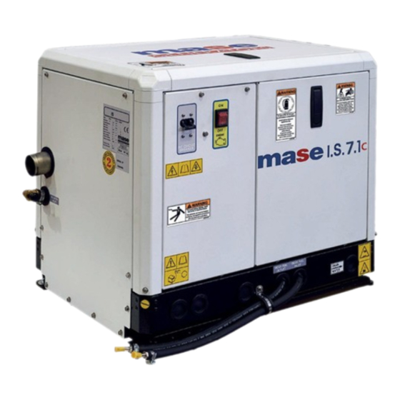
Summary of Contents for Mase IS 7.1
- Page 1 MANUALE USO, MANUTENZIONE E INSTALLAZIONE USE, MAINTENANCE AND INSTALLATION MANUAL IS 7.1 Rev.4 F.M. 19/06/2013 cod.42778 Tipo modello N° matricola Codice...
- Page 2 IS 7.1...
- Page 3 Grazie per aver scelto un prodotto MASE. Mase Generators è un’azienda leader nel settore dei gruppi elettrogeni ed offre la più vasta gamma di pro- dotti, in grado di spaziare dai piccoli generatori portatili da 1 KW fino ad unità da 1600 KVA per applicazioni speciali.
-
Page 4: Table Of Contents
..... 44 3.7.5Arresto d’emergenza ........29 SCHEMI ELETTRICI ........45 UTILIZZO DEL GRUPPO ELETTROGENO ..30 10.1 Schema elettrico IS 7.1 ........45 4.1 Controlli preliminari ..........30 4.2 Rifornimento carburante ........30 4.3 Avviamento del gruppo elettrogeno ....31 4.4 Arresto del gruppo elettrogeno ...... -
Page 5: Definizioni Usate
IS 7.1 DEFINIZIONI UTILIZZATE - I vocaboli usati sono quelli del linguaggio tecnico corrente e dove si è ritenuto necessario si riportano di seguito il significato - Gruppo elettrogeno E’ l’insieme di un motore a combustione interna a pistoni e un generatore di corrente alternata sincrono 2/4 poli autoeccitato, uniti tra loro per realizzare una centrale di autoproduzione di energia elettrica. - Page 6 IS 7.1 - Connessione in cattivo stato Le parti attive non sono completamente ricoperte con un isolamento che possa essere rimosso solo mediante distruzione, le connessioni presentano una incertezza nel collegamento causata da un labile serraggio delle parti e da uno sviluppo di ossido fra le parti.
-
Page 7: Premessa
Il continuo miglioramento ed evoluzione del prodotto potrebbero aver comportato modifiche al gruppo elettrogeno che non sono comprese in questa pubblicazione. Ogni volta che sorge un problema riguardante la macchina o questa pubblicazione consultare Mase Generators SPA per le informazioni più recenti disponibili. -
Page 8: Informazioni Generali
IS 7.1 1 INFORMAZIONI GENERALI DI SICUREZZA 1.1 U SO CONFORME Il gruppo elettrogeno è adatto a produrre autonomamente energia elettrica nei limiti di tensione e potenza dichiarati dal costruttore. E’ vietato ogni altro uso al di fuori del campo di impiego già citato: la macchina è destinata ad un uso marino. -
Page 9: Simboli Di Sicurezza
IS 7.1 ISTRUZIONI PER LA SICUREZZA Le attrezzature elettromeccaniche, inclusi i gruppi generatore, gli interruttori di commutazione, le apparecchiature elettriche di comando, e gli accessori, possono provocare danni alle persone e, qualora vengano installati, utilizzati o siano soggetti a operazioni di manutenzione non idonee, mettere in serio pericolo la vita delle persone stesse. Per evitare incidenti è... -
Page 10: Simbologia Sul Gruppo Elettrogeno
IS 7.1 1.4 S IMBOLOGIA SUL GRUPPO ELETTROGENO - 10... -
Page 11: Significato Delle Etichette Di Sicurezza
IS 7.1 1.5 S IGNIFICATO DELLE ETICHETTE DI SICUREZZA • Queste etichette avvertono l’utente su eventuali pericoli che possono causare gravi lesioni. Leggere attentamente il significato e le precauzioni descritte nel presente manuale. • Se l’etichetta si stacca o diventa illeggibile, sostituirla con una nuova richiedendola ad un rivenditore autorizzato mase. - Page 12 IS 7.1 Simboli di Pericolo Significato PREVENZIONE DA FUOCO Può provocare seri danni o la morte. - Avviare il G.E. solamente dall'interruttore di avviamento senza carichi applicati, con interruttore del gruppo in posizione neutrale. L'avviamento improvviso del gruppo elettrogeno può causare seri infortuni personali.
- Page 13 IS 7.1 Simboli di Pericolo Significato GAS DI SCARICO Monossido di carbonio. Utilizzo del gruppo generatore. Il monossido di carbonio può provocare forte nausea, svenimenti, o la morte. Il monossido di carbonio è un gas inodore, incolore, insapore e non irritante, in grado, se inalato anche solo per breve tempo, di provocare la morte.
- Page 14 IS 7.1 Simboli di Pericolo Significato BATTERIA Non venire in contatto con il liquido elettrolita della batteria Adeguata ventilazione nella zona batteria. Tenere ben ventilata l'area attorno alla batteria, prestando attenzione a tenere scintille, fiamme libere e altre forme di accensione lontane. Durante il funzionamento del gruppo elettrogeno avviene la ricarica della batteria e la produzione gas idrogeno che può...
-
Page 15: Documenti Di Riferimento
IS 7.1 1.6 D 1.8 M OCUMENTI DI RIFERIMENTO ARCATURA Le istruzioni per l'uso fornite con ciascun gruppo La targa predisposta per i gruppi elettrogeni contiene elettrogeno sono costituite da una raccolta di documenti tutti i dati identificativi in conformità alla norma ISO... -
Page 16: Caratteristiche Generali
IS 7.1 2 CARATTERISTICHE GENERALI Il gruppo elettrogeno è stato progettato per l'impiego in campo marino e utilizza motorizzazioni di alta affidabilità del tipo diesel 1500/1800 giri con raffreddamento ad aria/ acqua. Particolare attenzione è stata posta al grado di... -
Page 17: Pannello Comandi E Strumenti
IS 7.1 EQUIPMENT 120 V GROUND 2.2 P ANNELLO COMANDI E STRUMENTI VERSIONE STANDARD Ogni gruppo elettrogeno dispone di un pannello strumenti per i comandi e i controlli sul quale si trovano i seguenti componenti: 1) CONTAORE 2) PULSANTE OFF... -
Page 18: Tabella Caratteristiche Tecniche
IS 7.1 2.3 T ABELLA CARATTERISTICHE TECNICHE IS 7.1 MODELLO CARATTERISTICHE GENERALI POTENZA MASSIMA (LTP) POTENZA CONTINUA (PRP) FATTORE DI POTENZA (Cos Φ) TENSIONE NOMINALE 120-240 FREQUENZA NOMINALE GRADO DI PROTEZIONE IP 23 TEMP.MAX DI UTILIZZO °C - °F 40 - 104 TEMP.MIN DI UTILIZZO... -
Page 19: Installazione
IS 7.1 3 INSTALLAZIONE Il generatore deve essere installato solo da tecnici installatori qualificati. Malfunzionamenti dovuti ad una errata installazione possono causare infortuni o morte. 3.1 C ARATTERISTICHE DEL VANO - Il generatore deve essere installato in un locale suffi- cientemente areato, in grado di assicurare la quantità... -
Page 20: Circuito Acqua Di Raffreddamento
IS 7.1 3.5 C IRCUITO ACQUA DI RAFFREDDAMENTO Il motore viene raffreddato da un sistema a circuito aperto nel quale circola acqua di mare. All'atto dell'installazione è necessario predisporre un circuito di adduzione dell'acqua di mare per il raffredda- mento e un sistema di scarico per la miscela di gas di combustione ed acqua. -
Page 21: 2Componenti
IS 7.1 3.5.2 C OMPONENTI Nel caso il gruppo venga installato ad un altezza superiore ad 1m (3.3 ft). sopra la linea di galleg- gia-mento, è necessario montare una valvola di non ritorno (rif.2) dopo la presa a mare che impedisce lo svuotamento del circuito acqua a motore spento. -
Page 22: 3Installazioni Tipiche
IS 7.1 3.5.3 I NSTALLAZIONI TIPICHE IPICA INSTALLAZIONE CON GRUPPO ELETTROGENO SOPRA LA LINEA DI GALLEGGIAMENTO IPICA INSTALLAZIONE CON GRUPPO ELETTROGENO SOTTO LA LINEA DI GALLEGGIAMENTO - 22... - Page 23 IS 7.1 mase IPICA INSTALLAZIONE CON GRUPPO ELETTROGENO CON SEPARATORE SOPRA LA LINEA DI GALLEGGIAMENTO mase IPICA INSTALLAZIONE CON GRUPPO ELETTROGENO CON SEPARATORE SOTTO LA LINEA DI GALLEGGIAMENTO - 23...
- Page 24 IS 7.1 IPICA INSTALLAZIONE CON GRUPPO ELETTROGENO CON SEPARATORE GENSEP SOPRA LA LINEA DI GALLEGGIAMENTO IPICA INSTALLAZIONE CON GRUPPO ELETTROGENO CON SEPARATORE GENSEP SOTTO LA LINEA DI GALLEGGIAMENTO - 24...
-
Page 25: 5Sistema Di Scarico
IS 7.1 3.5.5 S ISTEMA DI SCARICO Il sistema di scarico gas di combustione/acqua del gene- Marmitta ratore deve essere indipendente da quello dei motori principali.Vedi schemi installazione. La lunghezza del tubo dal punto più alto del condotto di scarico alla marmitta non deve supe- rare mt. -
Page 26: Circuito Combustibile
IS 7.1 3.6 C IRCUITO COMBUSTIBILE L'alimentazione del gruppo è a gasolio, ed avviene trami- te i raccordi contrassegnati dalle diciture "DIESEL FUEL INLET" (rif.1) e "DIESEL FUEL OUTLET" (rif.2); que- st'ultimo serve per il ritorno del combustibile in eccesso. -
Page 27: Collegamenti Elettrici
IS 7.1 3.7 C OLLEGAMENTI ELETTRICI 3.7.1 A LLACCIAMENTO BATTERIA Per l'avviamento del gruppo è necessario utilizzare una batteria indipendente a 12V. Essa va allacciata ai morsetti del generatore con cavi di sez. 25mm fino a distanze di 5m (16.4ft). con cavi di sez. -
Page 28: 3Allacciamento C.a
IS 7.1 Il cruscotto comandi và necessariamente installato, in quanto esso è indispensabile per il funzionamento del gruppo: non utilizzare dispositivi diversi dal comando fornito col gruppo, poichè essi potrebbero non essere compatibili con il generatore stesso. Eseguire l'allacciamento a batteria scollegata. -
Page 29: 4Commutazione Generatore - Rete
IS 7.1 - Assicurarsi che la somma dei carichi da alimentare non superi la potenza nominale gruppo elettrogeno. - Nonostante che il gruppo sia dotato di termico (rif.1), si raccomanda di interporre fra generatore e utenze elettriche protezioni magnetotermiche o similari, se- condo le tabelle di seguito riportate. -
Page 30: Utilizzo Del Gruppo Elettrogeno
IS 7.1 4 UTILIZZO DEL GRUPPO ELETTROGENO 4.1 C ONTROLLI PRELIMINARI Prima di iniziare qualsiasi procedura di avviamento è estre- mamente importante "familiarizzare" con il gruppo elettrogeno e i suoi comandi. Si dovrà inoltre eseguire un controllo di sicurezza visivo della macchina e dell'installa- zione. -
Page 31: Avviamento Del Gruppo Elettrogeno
IS 7.1 4.3 A VVIAMENTO DEL GRUPPO ELETTROGENO Prima di avviare il gruppo elettrogeno assicurarsi che tutti gli sportelli siano chiusi. Prima di avviare II gruppo accertarsi che i controlli preliminari descritti siano stati eseguiti. Avviamento Procedere all’avviamento premendo il tasto “ON” (rif. 4), si noterà... -
Page 32: Arresto D'emergenza
IS 7.1 4.5 A ’ RRESTO D EMERGENZA Per l’arresto di emergenza del gruppo in moto, agire sull’ interruttore d’emergenza portandolo su OFF. Eliminate le cause che hanno determinato la necessità di un arresto di emergenza. Per tornare in condizioni operative, occorre riportare l’interruttore d’emergenza su “ON”. -
Page 33: Cruscotto Comandi - Codici Allarmi
IS 7.1 5.3 C RUSCOTTO COMANDI ODICI ALLARMI Quando il gruppo si arresta, per l’intervento di una protezione, sul display (rif.1) del pannello comandi scom- pare l’indicazione delle ore di funzionamento e compare un codice ad indicare la causa dell’arresto del gruppo elettrogeno. -
Page 34: Manutenzione
IS 7.1 6 MANUTENZIONE 6.1 P 6.3 C REMESSA ONTROLLO OLIO MOTORE Si raccomanda di seguire scrupolosamente le indicazio- - Controllare il livello dell’olio tramite l’apposito tappo/ ni riportate sul manuale fornito dal Costruttore del moto- astina olio (rif.1). Il livello dell’olio deve sempre essere compreso tra le re, allegato ad ogni gruppo elettrogeno. -
Page 35: Controllo Olio Motore
IS 7.1 6.4 C AMBIO OLIO MOTORE Utilizzare olio per motori diesel I rabbocchi e i caricamenti di olio motore vanno eseguiti attraverso il foro (rif.1).Per la sostituzione dell’olio nel carter motore si procede togliendo l’astina di indicazione livello (rif.1) e agendo sull'apposita pompa di estrazione (rif.2) dopo aver tolto la vite che funge da tappo. -
Page 36: Sostituzione / Pulizia Del Filtro Pompa Carburante
IS 7.1 6.6 S OSTITUZIONE PULIZIA DEL FILTRO POMPA CARBURANTE Tale operazione si esegue tramite i seguenti passaggi: - rimuovere il tubo (rif.1) - sfilare il filtro (rif.2) - pulire o sostituire Per il rimontaggio ripetere le operazioni con sequenza inversa. -
Page 37: Disareazione Impianto Dell'impianto Di Alimentazione
IS 7.1 6.10 D ISAREAZIONE DELL IMPIANTO DI ALIMENTAZIONE Il gruppo è munito di spurgo nafta automatico. Qualora fosse necessario lo spurgo manuale premere il pulsante "ON" sul pannello comandi ed attendere 30 secon- di prima di avviare il gruppo. -
Page 38: Trapezoidale
IS 7.1 6.14 M ANUTENZIONE DELLA POMPA ACQUA MARE Almeno una volta all'anno è necessario controllare l'integri- tà della girante in gomma della pompa acqua mare. Prima di aprire la pompa acqua mare per l'ispezione della girante è necessario svuotare l'impianto di raffreddamento dall'acqua di mare come descritto al paragrafo 6.12... -
Page 39: Controllo / Sostituzione Della Cinghia
IS 7.1 6.16 C ONTROLLO SOSTITUZIONE DELLA CINGHIA ALTERNATORE Una seconda cinghia è utilizzata per trasmettere il moto di rotazione dalla puleggia dell'albero motore a quella della pompa del liquido a circuito chiuso e dell'alternatore DC caricabatteria (rif.1). Regolare la tensione della cinghia nel modo seguente: 10Kg (7-9 mm) allentare la vite di registro (rif.2) e spostare l'alternatore... -
Page 40: Lista Ricambi Consigliati
Filtro gasolio Anodo zinco Fusibili E’ disponibile un kit ricambi consigliati, richiedere alla rete assistenza mase o al servizio assistenza. 6.20 P ERIODI DI INATTIVITÀ Avviare il gruppo elettrogeno almeno una volta al mese. Se il gruppo elettrogeno deve rimanere inutilizzato per un lungo periodo, è... -
Page 41: Controlli Periodici E Manutenzione
○ (e successive) ○ Test di funzionamento del generatore ○ In presenza di questo simbolo è possibile effettuare autonomamente l'assistenza tecnica. ● In presenza di questo simbolo è obbligatorio effettuare l'assistenza tecnica presso un nostro rivenditore/officina MASE autorizzato. - 41... -
Page 42: Tavola Guasti
IS 7.1 6.19 T AVOLA GUASTI Il motorino di avviamento gira ma il motore principale non si avvia. - Verificare la presenza di carburante all’interno del serbatoio. (Rifornire) - Verificare il funzionamento dell’elettrovalvola e pompa carburante. (Consultare Centro Assistenza) - Eseguire l'operazione di spurgo da bolle d'aria all'interno del circuito di alimentazione. -
Page 43: Trasporto, Imballo, Stoccaggio Sollevamento E Movimentazione
SOLLEVAMENTO E MOVIMENTAZIONE 7.1 T RASPORTO IMBALLO E STOCCAGGIO Imballo: Viene fornito direttamente dalla ditta Mase Generators. Il peso totale del gruppo elettrogeno imballato si trova al paragrafo 2.3 “Tabella caratteristiche tecniche”. Trasporto: Durante il trasporto, il gruppo elettrogeno, (con o senza imballo) deve essere protetto dagli agenti atmosferici, esso non deve essere capovolto e deve essere preservato da qualsiasi urto. -
Page 44: Garanzia, Responsabilita
8.1 G ARANZIA • I Gruppi elettrogeni mase, e tutti i suoi componenti sono garantiti privi di difetti, e sono coperti da garanzia per il periodo previsto dalla normativa vigente, a partire dalla data di acquisto. • Esclusione della da garanzia: mancata osservanza delle norme d’installazione, danni dovuti a disastri naturali, incidenti, difetti dell’impianto elettrico compreso il carico a cui il gruppo è... -
Page 45: 10 Schemi Elettrici
IS 7.1 10 SCHEMI ELETTRICI 10.1 S CHEMA ELETTRICO - 45... - Page 46 IS 7.1...
- Page 47 Thank you for having chosen a product MASE. As a leading generator manufacturer, Mase Generators offers a wide range of generators with an output from 1 KVA portable generators to 1600 KVA units for special applications.
- Page 48 3.7 Electrical connections ........27 WIRING DIAGRAMS ........45 3.7.1Battery connection ........... 27 3.7.2Control panel connection ......... 27 10.1 Wiring diagrams IS 7.1 ........45 3.7.3A.C. connection..........28 3.7.4Generator-network switching ......29 3.7.5Emergency stop ..........29 USING THE GENERATOR ......30 4.1 Preliminary checks ..........
-
Page 49: Definitions Used
A person able to evaluate the job assigned to him and recognise the possible dangers on the basis of training at the MASE training centres, with professional experience and knowledge of the equipment in question and of the possible dangers deriving in the event of negligent behaviour. - Page 50 IS 7.1 - Connection in bad state The live parts are not fully covered with insulation removable by destruction only, the connections are not secure because of unstable tightening of the parts and a development of oxide between the parts.
-
Page 51: Preliminary Prescriptions
Ongoing improvement and development of the product may have led to modifications to the generator which are not included in this publication. Whenever a problem concerning the generator or this publication arises, consult with Mase Generators SPA for the latest information available. -
Page 52: General Informations
IS 7.1 1 GENERAL INFORMATIONS 1.1 C ONFORM USE The generator is suitable for independent production of electrical energy within the voltage and wattage limits declared by the manufacturer. Any other use outside the already stated field of use is prohibited: the generator is intended for marine use. -
Page 53: Safety Symbols
IS 7.1 SAFETY INSTRUCTIONS The electromechanics equipments, included the generating sets, switch, command electric equipments and accessories, can cause damages to people and,if they are installed, used or mainteined with not qualified operations, they can put in serious danger the life of people. To avoid accidents is necessary to know the potential risks and operate with caution.Read and follow all the precautions and the instructions for the safety. -
Page 54: Symbols On The Generator Group
IS 7.1 1.4 S YMBOLS ON THE GENERATOR GROUP - 10... -
Page 55: Safety Label Informations
IS 7.1 1.5 S AFETY LABEL INFORMATIONS • These labels warn the user of any danger which may cause serious injury. Carefully read the meaning and the precautions described in this manual. • If the label detaches or becomes illegible, replace it with a new one which can be requested from an authorised mase dealer. - Page 56 IS 7.1 Danger Symbols Meaning PREVENTING FIRE Can cause severe injury or death. • Start • Start the engine only from a starter switch without any load or in neutral posi- tion of the clutch of machine unit. The machine unit suddenly starts to move or generates power to cause serious personal injury.
- Page 57 IS 7.1 Danger Symbols Meaning EXHAUST SYSTEM Carbon monoxide. Group generator use. Carbon monoxide can cause severe nausea, fainting, or death. Carbon monoxide is an odorless, colorless,tasteless, non irritating gas,able to, if inhaled only also for brief time to provoke the death.
- Page 58 IS 7.1 Danger Symbols Meaning BATTERY Do not touch the electrolitic battery acid Sufficient ventilation of the battery area. • Keep the area around the battery well ventilated, paying attention to keep sparks, open flame and any other form of ignition away. During engine running or charging battery, hydrogen gas is produced from the battery and can be easily ignited.
-
Page 59: Reference Documents
IS 7.1 1.6 R 1.8 M EFERENCE DOCUMENTS ARKING The instructions for use provided with each generator The generator identification plate carries all the are made up of a collection of documents of which this identification data in accordance with the provisions for manual represents the General Part. -
Page 60: General Characteristics
IS 7.1 2 GENERAL CHARACTERISTICS The generators have been designed for use in the marine field, using highly reliable 1500/1800 rpm air/ water-cooled diesel engines. Particular attention has been paid to the degree of protection against external agents, engine protection and protection of the electrical... -
Page 61: Command And Control Panel
IS 7.1 EQUIPMENT 120 V GROUND 2.2 C OMMAND AND CONTROL PANEL STANDARD VERSION Each generator is fitted with an instrument panel for commands and controls with the following components: 1) HOURCOUNTER 2) OFF BUTTON 3) START BUTTON 4) ON BUTTON... -
Page 62: Table Of Technical Characteristics
IS 7.1 2.3 T ECHNICAL CHARACTERISTICS TABLE IS 7.1 MODEL GENERAL FEATURES MAX POWER (LTP) CONTINUOUS POWER (PRP) POWER FACTOR (Cos Φ) RATED VOLTAGE 120-240 RATED FREQUENCY GRADE OF PROTECTION IP 23 MAX TEMP. OF USE °C - °F 40 - 104 MIN TEMP. -
Page 63: Installation
IS 7.1 3 INSTALLATION The generator may only be installed by qualified technicians. Malfunctioning due to improper installation may cause injury or death. 3.1 G ENERATOR HOUSING CHARACTERISTICS - The generator must be installed in a sufficiently ventilated room able to assure the small amount of air required for engine combustion. -
Page 64: Cooling Water Circuit
IS 7.1 3.5 C OOLING WATER CIRCUIT The generator engine is cooled by an open-circuit system in which seawater circulates. At the time of installation, a seawater feed circuit must be arranged for cooling, and an exhaust system for the combustion gas and water mixture. -
Page 65: 2Components
IS 7.1 3.5.2 C OMPONENTS If the generator is installed at a height over 1m (3.3ft) above the waterline, a check valve (ref.2) must be fitted after the seawater intake to prevent the water circuit from emptying out when the engine is off. If the circuit is empty, the water pump impeller may be damaged during starting. -
Page 66: 3Typical Installations
IS 7.1 3.5.3 T YPICAL NSTALLATIONS YPICAL INSTALLATION WITH GENERATOR ABOVE THE WATERLINE YPICAL INSTALLATION WITH GENERATOR UNDER THE WATERLINE - 22... - Page 67 IS 7.1 mase YPICAL INSTALLATION WITH GENERATOR ABOVE THE WATERLINE WITH WATER GAS SEPARATOR mase YPICAL INSTALLATION WITH GENERATOR UNDER THE WATERLINE WITH WATER GAS SEPARATOR - 23...
- Page 68 IS 7.1 YPICAL INSTALLATION WITH GENERATOR ABOVE THE WATERLINE WITH GENSEP WATER GAS SEPARATOR YPICAL INSTALLATION WITH GENERATOR UNDER THE WATERLINE WITH GENSEP WATER GAS SEPARATOR - 24...
-
Page 69: 5Exhaust System
IS 7.1 3.5.5 E XHAUST SYSTEM The generator combustion gas/water exhaust system Muffler must be independent of that of the main engines (see installation diagrams). The pipe length from the highest point of the exhaust pipe to the exhaust must not exceed 2 m. -
Page 70: Fuel Circuit
IS 7.1 3.6 F IRCUIT The generator is diesel-powered by means of the unions marked "DIESEL FUEL INLET" (rif.1) e "DIESEL FUEL OUTLET" (rif.2); the latter serves to return excess fuel. The fuel pipes must be in hydrocarbon-resistant rubber with an inside diameter of 8mm (0.31in). -
Page 71: Electrical Connections
IS 7.1 ELECTRICAL CONNECTIONS 3.7.1 BATTERY CONNECTION Use a 12V stand-alone battery to start the generator. Connect it to the generator terminals using cables of 25mm cross-section for a distance up to 5m (16.4ft) or cables of 35mm cross-section for longer... -
Page 72: C. Connection
IS 7.1 The control panel must necessarily be installed as it is essential for generator operation. Do not use devices different from the control provided with the generator, since they may be incompatible with the generator. Make the connection with the battery detached. -
Page 73: 4Generator-Network Switching
IS 7.1 - Make sure that the sum of the generator loads doesn't overcome the nominal power of the generator group. - Despite the group is provided with a thermal switch (rif.1), it's recommend to interpose magnetothermal protections or similar between generator and electric users, according to the following table. -
Page 74: Using The Generator
IS 7.1 4 USING THE GENERATOR 4.1 P RELIMINARY HECKS Before beginning with any starting procedures, it is extremely important to “familiarise” yourself with the generator and its controls. Furthermore, visually inspect the generator and the installation. Any source of real or potential risk must be eliminated before proceeding. -
Page 75: Starting The Generator
IS 7.1 STARTING THE GENERATOR Before starting the generator check that all the doors is closed. Before starting the generator ensure that all the preliminary checks have been carried out. Starting Proceed with starting by pressing the ON button OPEN (ref.4),You will note that all the LEDs come on while a... -
Page 76: Emergency Stop
IS 7.1 4.5 E MERGENCY STOP For an emergency stop of the generator, set the emergency switch to OFF. Once the causes that determined the need for an emergency stop have been eliminated, reset the emergency switch to ON to return to the operating conditions. -
Page 77: Control Panel - Alarm Codes
IS 7.1 5.3 C ONTROL ANEL LARM ODES When the generator stops because one of the safety switches has tripped, the indication of the hours of operation disappears from the control panel display (ref.1) and a code appears to indicate the cause of the generator stop. -
Page 78: Maintenance
IS 7.1 6 MAINTENANCE 6.1 P REAMBLE 6.3 E NGINE HECK It is recommended to strictly follow the instructions in the manual provided by the engine manufacturer, - Check the oil level by means of the cap/dipstick (ref.1). which accompanies each generator. -
Page 79: Engine Oil Check
IS 7.1 is positioned horizontally. ENGINE OIL CHANGE Use diesel engine oil Top up the engine oil through the hole (ref.1). To change the oil in the engine oil sump, take out the dipstick (ref.1) and operate the extraction pump (ref.2) after removing the screw that acts as cap. -
Page 80: Replacing / Cleaning The Fuel Pump Filter
IS 7.1 6.6 R EPLACING LEANING ILTER This operation is carried out following the steps below: - Remove the pipe (ref.1) - Slide out the filter (ref.2) - Clean or replace it For reassembly repeat the operations in reverse order. -
Page 81: Air Filter
IS 7.1 6.10 B LEEDING THE FUEL SYSTEM The generator is equipped with an automatic fuel bleed valve. Should manual bleeding be necessary, press the ON button on the control panel and wait 30 seconds before starting the generator. For the manual bleeding activate the fuel pump pressing the “START”... - Page 82 IS 7.1 6.14 S EAWATER PUMP MAINTENANCE At least once a year check the integrity of the rubber seawater pump impeller. Before opening the seawater pump to inspect the impeller, drain the seawater from the cooling system as described in paragraph 6.12.
-
Page 83: Checking / Replacing The V-Belt
IS 7.1 6.16 C HECKING REPLACING THE ALTERNATOR V BELT A second belt is used to transmit the rotary motion from the drive shaft pulley to that of the closed-circuit coolant pump and the battery charger DC alternator (rif.1). Adjust the belt tension as follows: Loosen the adjusting screw (rif.2) and move the battery... -
Page 84: List Of Recommended Spare Parts
Fuel filter Zinc anode Fuses A kit with recommended spare parts is available and may be ordered from the Mase Service Network or Technical Service. 6.20 P ERIODS OF INACTIVITY Start up the generator at least once a month. If the... -
Page 85: Period Checks And Maintenance
IS 7.1 6.18 P ERIOD CHECKS AND MAINTENANCE PERIOD CHECKS AND MAINTENANCE Every 50 Every 100 Every 200 Every 400 Before Every Every Perform service at intervals indicated hrs.or 1 hrs.or 2 hrs.or 3 hrs.or starting 500 hrs. 800 hrs. -
Page 86: Anomalies, Causes And Remedies
IS 7.1 6.19 ANOMALIES CAUSES AND REMEDIES The starter motor turns but the main engine does not start - Check that there is fuel in the tank. (Fill up) - Check the elctrovalve functioning and the fuel pump. (Consult Service Centre) - Bleed the air bubbles from the fuel circuit. -
Page 87: Handling And Packaging
7 TRANSPORT, STORAGE, LIFTING AND, HANDLING AND PACKAGING 7.1 T RANSPORT AND STORAGE Packaging: Supplied directly by Mase Generators. The total weight of the packed generator is given in Paragraph 2.3 “Table of technical characteristics”. Transport: During transport the generator (with or without... -
Page 88: Guarantee And Responsability
8.2 L IMITS OF RESPONSIBILITY MASE GENERATORS S.p.A is responsible for anything regarding the safety, reliability and performance of the Generator on the condition that: • The generator is used by persons trained through the use and maintenance manual. -
Page 89: Wiring Diagrams
IS 7.1 10 WIRING DIAGRAM 10.1 W IRING DIAGRAM - 45... - Page 90 Mase Generators S.p.a. • Via Tortona, 345 • 47522 Cesena (FC) ITALY • Tel. (+39) 0547.35.43.11 Fax (+39) 0547.31.75.55 • www.masegenerators.com • e-mail mase@masegenerators.com...
Need help?
Do you have a question about the IS 7.1 and is the answer not in the manual?
Questions and answers