Mase IS. 2.5 Workshop Manual
Hide thumbs
Also See for IS. 2.5:
- Use and maintenance manual (13 pages) ,
- Installation manual (12 pages)
Table of Contents
Advertisement
Quick Links
Advertisement
Table of Contents

Subscribe to Our Youtube Channel
Related Manuals for Mase IS. 2.5


Summary of Contents for Mase IS. 2.5
- Page 1 IS. 2.5 50 Hz WORKSHOP MANUAL...
-
Page 2: Table Of Contents
IS 2.5 Index Machine identification......5 Generators composition ......5 TOOL TABLE .......... 9 ALTERNATOR ........13 Stator ............ 15 3.1.1 Power windings ........15 3.1.2 Excitation windings ....... 17 3.1.3 Alternator thermostat ......17 Battery charger windings ....3.1.4 Rotor ............. 21 3.2.1 Rotor winding (n°2) ....... - Page 3 IS 2.5 SCREW SHUT ........95 SPARE PARTS ........96 ENGINE-ALTERNATOR ...... 96 FRAME ..........98 WIRING DIAGRAM ....... 101...
- Page 4 IS 2.5 SERIAL No.
-
Page 5: Machine Identification
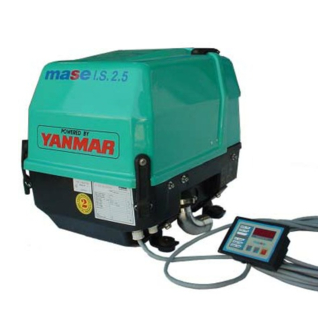
IS 2.5 1 Machine identification (Fig.1) 1 - Manufacturer 2 - Machine code 3 - Year of construction 4 - Power factor 5 - Declared frequency 6 - Continuous power 7 - Rated voltage 8 - Rated current 9 - Weight 10 - Serial number The machine code number, the serial number and the year of construction must always be... - Page 6 IS 2.5...
- Page 7 IS 2.5 8A- Connection to battery + 8B-Connection to battery - 9- RPM adjusting screw of engine 10- Engine air filter 11- Staff oil level 12- Seawater pump 13- Fuel pump 14- Oil filter cartridge 15- Oil fillercap 16- Electric line connection box 17- Battery charger regolator 18- Water/air heat exchanger 19- Exhaust manifold...
- Page 8 IS 2.5...
-
Page 9: Tool Table
IS 2.5 2 TOOL TABLE Denomination: Torque spanner Use: To tighten the nuts and bolts to the prescribed torque Denomination: Battery tester Use: To check the electrolyte level of the battery Denomination: Digital thermometer Use: Measures the temperature of the components Denomination: Contact tachometer Use: Measures the rpm of the rotary shaft by... - Page 10 IS 2.5...
- Page 11 IS 2.5 Denomination: Tester Use: Measures the AC/DC voltage, the resistors and the diodes Denomination: Amperometric caliper Use: Measures the AC voltage, frequency (engine rpm) and AC current. The power drawn from the generator can thus be measured. Denomination:Ammeter Use: Measures the line current connecting it in series Denomination:Frequency meter Use: Measures the frequency (engine rpm)
- Page 12 IS 2.5...
-
Page 13: Alternator
IS 2.5 3 ALTERNATOR The generators of the IS 2.5, series are equipped with a brushless, synchronous, 2-pole, self- regulating, self-excited alternator with 1 capacitor (Fig. 2 Ref. 22) connected to the auxiliary winding for stator excitation. The alternator generates alternate voltage available at the terminals at a frequency of 50/60 Hz (corresponding to the speed of the prime mover of 3000/3600 rpm) according to... - Page 14 IS 2.5 50(60)
-
Page 15: Stator
IS 2.5 Stator (Fig.6, ref5) 3.1.1 Power windings (Fig.6, ref.1) Features: Test method: - Ensure that the onboard thermal switch is ar- moured - Disconnect from the terminal board, the wires coming from the stator, marked by the letters P - Verify that the resistance values between the two pairs of wire terminals P and P... - Page 16 IS 2.5...
-
Page 17: Excitation Windings
IS 2.5 3.1.2 Excitation windings (Fig.6, ref.2) Features: 50Hz 60Hz Colore / Color n° colore IS 3,5 n° colore IS 4,0 Colore / Color ECCITAZIONE / Rosso-Red Rosso-Red ECCITAZIONE 2,76 2,29 2,52 2,08 EXCITATION 50 Nero-black 60 Bianco-White Test method - Remove the protective cap. - Page 18 IS 2.5...
-
Page 19: Battery Charger Windings
IS 2.5 3.1.4 Battery charger windings (Fig.6, Ref.3) Characteristics: 50Hz 60Hz n° colore IS 3,5 n° colore IS 4,0 CARICA Blù-Blue Verde-Green 0,162 0,127 0,13 0,11 BATTERIA Blù-Blue Verde-Green Test method - Disconnect the battery from the generator. - Disconnect the 2 cables marked 5 or 6 (Fig. 9 Ref.1) from the regulator (the corresponding symbols “~”... - Page 20 IS 2.5...
-
Page 21: Rotor
IS 2.5 Rotor 3.2.1 Rotor winding (n°2) Features: IS 3,5 4,0 50 / 60HZ Rotore- Rotor 2,11 2,37 Condensatore - Capacitor 25micrF Test method: -Check that the resistance between the two ends of the diodes falls within the values indicated. (Fig.10). REMEDY: Replace the rotor IMPORTANT Failed output voltage may exceptionally be caused... - Page 22 IS 2.5...
-
Page 23: Rotor Diodes (N°2)
IS 2.5 3.2.2 Rotor diodes (n°2) Characteristics : SKR 26/16 Test method: -Disconnect the cables at end A of the 2 diodes (Fig. 11) -Check with a tester with the + prod on A and the - prod on K if there is continuity. -Check that when inverting the tester prods there is no continuity. - Page 24 IS 2.5...
-
Page 25: Capacitors
IS 2.5 Capacitor Characteristics - 25 uF 450V 50 Hz: Test method: -Disconnect the cables from the capacitor. -Check that the resistance at their ends is not less than 200K Ohm. N.B.: This test is done to check that the capacitor is not in short-circuit. - Page 26 IS 2.5...
-
Page 27: Engine
IS 2.5 Unit Model L 70 AE Type 4-stroke, vertical, air-cooled diesel engine direct No. of cylinders - Bore x Stroke 1\78X62 1/70x55 Cylinder block material Alluminium Displacement Rotation speed 3000 3600 Continuous power Power* Maximum power Direction of rotation Anticlockwise (flywheel view) Compression ratio 20:1... -
Page 29: Maintenance
IS 2.5 4.2 Maintenance For long life and proper functioning of the generator, the checking and maintenance schedule indicated in the following table must be respected. How to execute these operations is described, for the part relating to the engine, in the use and maintenance handbook or in the workshop manual of the engine manufacturer. - Page 30 IS 2.5...
- Page 31 IS 2.5...
-
Page 32: Trouble-Shooting
IS 2.5 4.3 Trouble-shooting... - Page 33 IS 2.5 4.3 Trouble-shooting...
- Page 34 IS 2.5 Fuel system diagram...
-
Page 35: Fuel
IS 2.5 4.4 fuel 1. Proper use of diesel fuel Use diesel fuel of a quality equivalent to or higher than ISO 8217 DMA, BS 2869 Part 1 Class A1 or Part 2 Class A2. (cetane number: min. 45) Provide the customers with adequate instructions on proper use of diesel fuel in order to prevent the following problems from arising:... - Page 36 IS 2.5...
-
Page 37: Electric Diesel Fuel Pump
IS 2.5 4.5 Electric diesel fuel pump Characteristics : 12V Test method: - Check that the filter (Fig.15 Ref.1) is not dirty. -Disconnect the cables. -Check functioning with a 12V battery connecting the (+) of the battery to the (+) of the pump and the (-) of the battery to the (-) of the pump. - Page 38 IS 2.5 Lubrication system diagram Ambient temperature (°C) at which the engine is used Recommended SAE gradations...
-
Page 39: Lubrication
IS 2.5 Lubrication 1. Proper use of engine oil Proper use of engine oil guarantees: (1) Adequate protection of the engine parts subject to friction against engine friction and wear. (2) Protection of the engine parts against rust and corrosion. (3) Efficient cooling of the parts which reach high temperatures. - Page 40 IS 2.5...
-
Page 41: Sensors
IS 2.5 5 Sensors 5.1 Closed-circuit engine thermal switch Characteristics: 115° C n.o. contact. Test method - Immerse the thermostat in a container of antifreeze fluid or oil. - Heat the fluid and measure the temperature. If the tester shows continuity values at a temperature of 112-118°C, the thermal switch is in good condition. - Page 42 IS 2.5...
-
Page 43: Open-Circuit Engine Thermostat (Sea)
IS 2.5 5.2 Open-circuit engine thermostat (sea) Characteristics: 70°C N.O. contact Test method - Immerse the thermostat in a container of water. - Heat the fluid and measure the temperature. - If the tester shows continuity values at a temperature of 65-75°C, the thermostat is in good condition. - Page 44 IS 2.5...
-
Page 45: Oil Pressure Switch
IS 2.5 5.3 Oil pressure switch Characteristics: n.c.= normally closed (motore in stopped) n.o.= normally open (motore in run) Test method: -Start the engine. -Remove the cable from the pressure switch and move the tester probes towards the terminal of the switch and the cylinder block. - Page 46 IS 2.5 Circuit/seawater cooling system diagram...
-
Page 47: Sea Water Cooling
IS 2.5 6 SEA WATER COOLING "Seawater/circuit" system Characteristics: open-circuit liquid with seawater. Seawater pump flow rate 25 l/min. - Page 48 IS 2.5...
-
Page 49: Water Pump
IS 2.5 Water pump Characteristics:type Johnson (F35B-8) Test method: -Visual -Remove the screws (Fig.21 Ref.1) and remove the pump cover (Fig.21 Ref.2). -Remove the rotor. REMEDY: If damaged, replace the rotor N.B.For proper functioning of the generator, this check must be carried out every 300 hours or after one year. - Page 50 IS 2.5...
-
Page 51: Water Pump Belt
IS 2.5 6.3 Water pump belt Test method: -Press on the belt with about 10 kg and check that flexure does not exceed 0.5cm (Fig.22 Ref.1). REMEDY: Tighten the belt, loosen the water pump retaining bolts (Fig.22 Ref.2). -Pull on the belt acting on the pump adjusting screw (Fig.22 Ref.3). - Page 52 IS 2.5...
-
Page 53: Water/Air Heat Exchanger
IS 2.5 6.4 Water/air heat exchanger Characteristics: tube bundle / radiant mass Test method - Check that there is no sedimentation or foreign bodies in the tubes (Fig.23) . - Check that the zinc pad(Fig.23 Ref.2) is not worn REMEDY - Unscrew the zinc pad-holder cap (Fig.23 Ref.1) ;... - Page 54 IS 2.5...
-
Page 55: Adjustments
IS 2.5 7 ADJUSTMENTS 7.1 Rpm adjustment Since the alternator is type four-pole the following correspondence is valid: 3000 3600 Test method: -Check the output frequency of the power terminals with a suitable instrument (vibrating-reed frequency meter or digital or with revolution counter). For accurate reading of the voltage and amperage values use only instruments that show the true effective value... - Page 56 IS 2.5...
-
Page 57: Closing Cover Motor
IS 2.5 Closing cover motor Control's method: - To verify that the cover is closed in correct way without too mobility towards the box. - Page 58 IS 2.5...
-
Page 59: Engine Air Filter Cleaning
IS 2.5 Engine air filter cleaning Test method: - Check periodically the air filter condition. REMEDY - Remove the screws (Fig. 26 Ref. 1) - Remove the filtering element. - Wash with diesel fuel and dry with compressed air. An inefficient filter may cause loss of engine power and excessive smoke at the exhaust. - Page 60 IS 2.5...
-
Page 61: Level Oil Check
IS 2.5 7.4 Oil level check. Test method: - Check the oil level REMEDY To change the engine oil use the special manual pump (Fig. 27 Ref 4). It is recommended to drain the oil when it is still sufficiently warm to flow easily. - Page 62 IS 2.5...
-
Page 63: Electrical System
IS 2.5 8 ELECTRICAL SYSTEM 8.1 Command circuit Every generator group has a command to microprocessor for the commands and the controls. The command to microprocessor converses with the card relay of edge car which performs the functions of command in power. This is the center of control of the generator, on which the component followings are found: 1) HOURSMETER... - Page 64 IS 2.5...
- Page 65 IS 2.5 Code E - 81 This code indicates that the unit has stopped because the motor lubrication system pressure is insufficient. Code E - 82 This code indicates that the unit has stopped because the motor has reached too high temperatures. Code E - 83 This code indicates that the unit has stopped because the alternator has reached too high temperatures.
- Page 66 IS 2.5...
- Page 67 IS 2.5 MULTIPOLAR CABLE COLOR FUNCTION + batt12v black - batt 12v pink electrov./pum yellow start green High engine temp. grey Low oil press. blù High altern. temp. Braid Cable shielding brown 115 / 120 a.c. white 115 / 120 a.c.
- Page 68 IS 2.5...
-
Page 69: Multicore Cable
IS 2.5 8.1.1 Multicore cable Characteristics : 7x0.35mm2 + 2x0.35mm2 multicore cable with double-shielding Test method: - Detach the connector from the control circuit and disconnect the cables from the relay board. - Check that there is no continuity between each of the 9 wires and also towards the metal shielding braid. - Page 70 IS 2.5...
- Page 71 IS 2.5 “Solenoid valve/fuel pump start” relay (Fig.31) Detach the relay from its socket. Check that there is continuity between the points 85-86 (12V coil). check that, powering the points 85-86 with a 12V battery, the contact 30-87 closes and vice versa.
- Page 72 IS 2.5...
-
Page 73: Stop Solenoid
IS 2.5 8.2 Stop solenoid Characteristics:12V, normally closed, coil resistance 18.3 ohm Testing method: -Disconnect the fast-on terminal (Fig.33 Ref.1). Verify that the resistance value between points 1 and 2 - Fig.33 is as reported above. REMEDY: Replace the fuel solenoid 8.3 Thermal switch (AC circuit breaker) Characteristics: 2-pole 14A - Disconnect the cables. - Page 74 IS 2.5...
-
Page 75: Engine Wiring
IS 2.5 Engine wiring Test method - Check that the cables and the junctions are not oxidised or flayed, in particular near the corners and edges of the underbody and near the seawater pipe joints. - Check that the Faston terminals are securely tightened on the components. - Page 76 IS 2.5 1 1 1 1 1 A VV.C.B. BATT. 12V...
-
Page 77: Battery Charger
IS 2.5 8.5 Battery charger Characteristics: 12V - after charging 14/14.3V Operation: The battery charger is powered by two identical windings, with a central common point, which generate alternate current. The two ends of the windings are connected directly to the pins ~ (Fig.36 Ref.2) on the battery charger, while the common is connected to the + battery (under the fuse) and the casing to the - battery. - Page 78 IS 2.5...
-
Page 79: Fuse
IS 2.5 8.6 FUSE 30A lamellar fuse characteristics Test method: - Extract the fuse. - Check the integrity of the blade. - With a tester check the continuity of the fuse. Remedy: replace the fuse. - Page 80 IS 2.5...
-
Page 81: Starter Motor
IS 2.5 8.7 Starter motor Characteristics:12V 0.8 KW Test method: -Disconnect the 2.5mm white cable. (with female Faston) (rif.1, fig.39). -Use a 12V battery connecting the (+) of the battery to the screw terminal and the (-) to the ground (starter motor casing) (fig.39).. - Page 82 IS 2.5 Terminal Cover Cathode plate Separator Battery body Felt Anode plate Grease Acceptable Insufficient Excessive Maximum level Minimum Fluid level level Battery tester Measuring the battery charge with the tester...
-
Page 83: Battery
IS 2.5 Battery Characteristics: Least capacity 70 Ah, 12V Test method: (1) Electrolyte level Check the electrolyte level in each cell. If insufficient, add deionised water until reaching the MAX level as shown in the figure. (2) Battery charge. Use a battery tester or a densimeter to check the battery condition. - Page 84 IS 2.5...
-
Page 85: Disassembly
IS 2.5 9 DISASSEMBLY 9.1 Removing the casing - Remove the top door and the top panel... - Page 86 IS 2.5...
- Page 87 IS 2.5 - - Remove the screws and then the panel...
- Page 88 IS 2.5...
-
Page 89: Removing The Alternator
IS 2.5 Remove the clamp (Fig.43, Ref.1) and then the exchanger (Fig.43, Ref.2). 9.2 Removing the alternator. Disconnect all the cables from the relay board and the termal switch. Remove the cover (Fig.43 Ref.3). - Page 90 IS 2.5...
-
Page 91: Removing The Alternator Cover On The Bearing Side
IS 2.5 Removing the alternator cover on the bearing side (Fig.47 Ref.1) - Remove the retaining screws of the alternator cover on the bearing side (Fig.47 Ref.2) - With the aid of an extractor, remove the cover (Fig.47 Ref.3) Componente Diametro filettatura x passo Coppie di serraggio (Nm) Component... - Page 92 IS 2.5...
-
Page 93: Removing The Stator
IS 2.5 Removing the stator (Fig.48 Ref.1) - With one screwdriver prise in the position indicated in Fig.48 Ref.2. - Remove the stator, taking care not to damage the rotor windings. - Page 94 IS 2.5...
-
Page 95: Removing The Rotor
IS 2.5 9.5 Removing the rotor. (Fig. 49 Ref. 1, 2, 3) - Undo the nut (Fig.49, Ref.1) - Hit the bearing with a wooden batten. If the rotor is not released at the first attempt, repeat the operation turning the rotor 180°. 9.6 Removing the rotor bearing (Fig. -
Page 96: Engine-Alternator
IS 2.5 Rev. / Rel. motore / alternatore FIG. 1 /2 IS 2.5 engine / alternator Rif. Cod. Qty. Descrizione Description 1 70821 Asta livello olio Oil dipstick 2 90905 Scatola filtro Air filter box 3 70812 Massa filtrante Sponge 4 10807 Portagomma Nipple... - Page 97 IS 2.5 Rev. / Rel. motore / alternatore IS 2.5 FIG. 1/2 engine / alternator Rif. Cod. Qty. Descrizione Description 20 50257 Puleggia pompa 50 Hz Pulley 20 50260 Puleggia pompa 60 Hz Pulley 21 70823 Manicotto carico olio Oil pipe 22 70824 Manicotto acqua Water pipe...
-
Page 98: Frame
IS 2.5 cassa Rev. / Rel. IS 2.5 FIG. 2/2 frame... - Page 99 IS 2.5 cassa Rev. / Rel. IS 2.5 FIG. 2/2 frame Rif. Cod. Qty. Descrizione Description 80542 Regolatore carica batt. Batt. charger regulator 31188 Condensatore Capacitor 31002 Fusibile lamellare 20 A Fuse 20 A 30925 Portafusibile Fuse carrier 30926 Piastrina portafusibili Fuse holder terminal 32690 Scheda relè...
- Page 100 IS 2.5...
-
Page 101: Wiring Diagram
IS 2.5 WIRING DIAGRAM SCHEMA ELETTRICO 50(60) 5(6) 5(6) 50 30... - Page 102 IS 2.5 ROTOR STATOR DIODE 3A VARISTOR PRINTED CIRCUIT RELAY POWER TERMINAL BOARD RELAY CIRCUIT TERMINAL BOARD CONTROL PANEL TERMINAL BOARD FUSE 1A CAPACITOR BATTERY CHARGER REGULATOR FUSE STARTER BATTERY FUEL PUMP FUEL SOLENOID OIL PRESSURE SWITCH OVERHEAD ENGINE THERMOSTAT WATER TERMOSTAT ALTERNATOR THERMOSTAT THERMAL SWITCH...
Need help?
Do you have a question about the IS. 2.5 and is the answer not in the manual?
Questions and answers