Sign In
Upload
Manuals
Brands
Mase Manuals
Portable Generator
I.S. 7.6
Mase I.S. 7.6 Manuals
Manuals and User Guides for Mase I.S. 7.6. We have
2
Mase I.S. 7.6 manuals available for free PDF download: Workshop Manual, Installation Manual
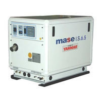
Mase I.S. 7.6 Workshop Manual (131 pages)
SILENT DIESEL GENERATORS
Brand:
Mase
| Category:
Portable Generator
| Size: 3 MB
Table of Contents
Italian
2
Table of Contents
2
Identificazione Della Macchina
5
Composizione Dei Gruppi Elettrogeni
5
Alternatore
13
Statore
15
Avvolgimenti DI Potenza
15
Avvolgimenti DI Eccitazione
17
Termostato Alternatore
17
Rotore
19
Avvolgimento DI Rotore (N°2)
19
Diodi Rotore (N°2)
21
Condensatori
23
Motore
25
Caratteristiche Tecniche
25
Manutenzione
26
Tavola Guasti
28
Combustibile
33
Pompa Gasolio Elettrica
35
Lubrificazione
35
Filtro Gasolio a Bicchiere
37
Sensori
39
Valvola Termostatica
39
Termointerruttore Motore a Circuito Chiuso
41
Sensore Temperatura
43
Termostato Motore a Circuito Aperto (Mare)45
45
Pressostato Olio
47
Sensore Pressione Olio
49
Raffreddamento
51
Pompa Acqua
53
Cinghia Pompa Acqua
55
Scambiatore DI Calore Acqua/Acqua
57
Scambiatore DI Calore Acqua/Aria
59
Regolazioni
61
Regolazione Dei Giri
61
Regolazione Serrature E Maniglie
63
Alternatore
113
Cassa
115
Marenizzazione
117
Pannello Comandi
119
English
5
Machine Identification
5
Generators Composition
5
Tabella Attrezzi
9
Tool Table
9
Alternator
13
Stator
15
Power Windings
15
Excitation Windings
17
Alternator Thermostat
17
Rotor
19
Rotor Winding (N°2)
19
Rotor Diodes (N°2)
21
Capacitors
23
Engine
25
Technical Features
25
Maintenance
27
Trouble-Shooting
30
Fuel
33
Electric Diesel Fuel Pump
35
Lubrication
35
Diesel Fuel Bowl Filter
35
Sensors
39
Thermostatic Valve
39
Closed-Circuit Engine Thermal Switch
41
Temperature Sensor
43
Open-Circuit Engine Thermostat (Sea)
45
Oil Pressure Switch
47
Oil Pressure Sensor
49
Impianto "Acqua Mare/Circuito Chiuso
51
Sea Water Cooling
51
Seawater/Closed-Circuit System
51
Water Pump
53
Water Pump Belt
55
Water/Water Heat Exchanger
57
Water/Air Heat Exchanger
59
Adjustments
61
Rpm Adjustment
61
Lock and Handle Adjustment
63
Impianto Elettrico
65
Cruscotto
65
Electrical System
65
Instrument Panel
65
Pannelli Strumenti a Distanza
67
Strumento Termometro Temperatura Acqua
67
Strumento Pressostato Olio
67
Remote Instrument Panels
67
Water Temperature Thermometer
67
Oil Pressure Switch
67
Pulsante START / STOP-Preriscaldo
69
Prolunga Comando a Distanza
69
START/STOP Preheating Button
69
Remote Control Extension
69
Fusibili Candelette
71
Relé DI Candelette (Glow Relay)
71
Glow Plug Fuses
71
Glow Relay
71
Contaore
73
Magnetoidraulico (AC Circuit Breaker)
73
Hour Counter
73
Magnetohydraulic Switch (AC Circuit Breaker)
73
Termico Linea 12V
75
Line Thermal Switch
75
Cablaggio Motore
77
Engine Wiring
77
Modulo Protezione Motore
79
Engine Protection Module
79
Alternatore Carica Batteria
81
Battery Charger Alternator
81
Elettromagnete Motore
83
Engine Electromagnet
83
Candelette Pre-Riscaldo 3 Pezzi
85
Pre-Heating Glow Plugs, 3 Pieces
85
Motorino Avviamento
87
Starter Motor
87
Batteria
89
Battery
89
Smontaggio 91
91
Removing the Alternator
101
Removing the Water/Air Exchanger Unit
103
Removing the Alternator Cover on the Bearing S
105
Removing the Rotor Bearing
109
Motore
111
Wiring Diagram
121
Versioni Speciali
123
IS 7.6 Cod.001351
124
Advertisement
Mase I.S. 7.6 Installation Manual (48 pages)
GENSET 50/60 Hz
Brand:
Mase
| Category:
Portable Generator
| Size: 1 MB
Table of Contents
Italiano
9
Table of Contents
9
1 Informazioni Generali
10
Scopo E Campo DI Applicazione del Manuale
10
Simbologia
10
2 Prescrizioni Per la Sicurezza Durante L'installazione E la Messa in Servizio
11
3 Installazione
11
Caratteristiche del Vano
11
Ancoraggio del Gruppo
11
Ventilazione
11
4 Circuito Acqua DI Raffreddamento
11
Sistema DI Adduzione Dell'acqua DI Mare
11
Tipica Installazione DI Gruppo Elettrogeno Sopra
12
La Linea DI Galleggiamento
12
Tipica Installazione DI Gruppo Elettrogeno Sotto la Linea DI Galleggiamento
12
Tipica Installazione DI Gruppo Elettrogeno con
12
Marmitta Separatrice Acqua/Gas DI Scarico Sopra
12
Componenti
12
Sistema DI Scarico
13
5 Circuito Combustibile
13
6 Collegamenti Elettrici
14
Allacciamento Batteria
14
Collegamento Pannello Comando a Distanza
14
Allacciamento C.a
14
Commutazione Generatore - Rete
15
7 Movimentazione
15
8 Riferimenti Schema Elettrico
15
Deutsch
25
1 Allgemeine Informationen
26
Zweck und Anwendungsbereich der Bedienungsanleitung
26
Symbole
26
2 Sicherheitsvorschriften während der Installation und Inbetriebnahme
27
3 Installation
27
Charakteristiken des Installationsraums
27
Verankerung des Aggregats
27
Belüftung
27
4 Kühlwasserkreis
27
Meereswasser-Zuflußsystem
27
Typische Installation des Generators Oberhalb der Wasserlinie (Abb. 4)
27
Typische Installation des Generators Unterhalb der Wasserlinie (Abb. 5)
28
Typische Installation des Generators mit Wasser/Abgas-Abscheidungsauspufftopf Oberhalb der Wasserlinie (Abb. 6) und Unterhalb der Wasserlinie (Abb. 7)
28
Bestandteilen
28
Auslaßsystem
29
5 Kraftstoffkreis
29
6 Elektroanschlüsse
29
Batterieanschluß
29
Anschluß des Schaltbretts
30
Wechselstrom-Anschluß
30
Umschaltung Generator-Netz
31
7 Beförderung
31
8 Erläuterungen zum Schaltplan
31
Français
33
1 Informations Generales
34
Objectif et Domaine D'application du Manuel
34
Symboles
34
2 Consignes de Sécurité Durant L'installation et la Mise en Service
35
3 Installation
35
Caractéristiques du Local
35
Ancrage du Groupe
35
Ventilation
35
4 Circuit D'eau de Refroidissement
35
Système D'amenée D'eau de Mer
35
Installation Typique Avec Groupe Électrogène au Dessus de la Ligne de Flottaison (Fig. 4)
35
Installation Typique Avec Groupe Électrogène Sous la Ligne de Flottaison (Fig. 5)
36
Installation Typique de Groupe Électrogène Avec
36
Pot Séparatrice Eau/Gaz Décharge au Dessus
36
(Fig. 6) et Sous (Fig. 7) de la Ligne de Flottaison
36
Composants
36
Système de Purge
37
5 Circuit du Combustible
37
6 Connexions Electriques
37
Branchement de la Batterie
37
Branchement du Tableau de Commande
38
Raccordement C.a
38
Commutation Générateur - Réseau
38
7 Deplacement
39
8 References Schema Electrique
39
Español
41
1 Informacion General
42
Simbología
42
2 Prescripciones de Seguridad para la Instalación y la Puesta en Servicio
43
3 Instalación
43
Características de la Caja
43
Anclaje del Grupo
43
Ventilación
43
4 Circuito del Agua de Refrigeración
43
Sistema de Aducción del Agua de Mar
43
Instalación Típica, con Grupo Electrógeno por Encima de la Línea de Flotación (Fig. 4)
43
Instalación Típica, con Grupo Electrógeno por Debajo de la Línea de Flotación (Fig. 5)
44
Instalación Típica, de Grupo Electrógeno con Marmita Separadora de Agua/Gas de Escape por Encima (Fig. 6) y Debajo (Fig. 7) de la Línea de Flotación
44
Ingredientes
44
Sistema de Escape
45
5 Circuito de Combustible
45
6 Conexiones Eléctricas
45
Conexiones de la Batería
45
Conexión del Tablero de Mandos
46
Conexiones a la C.A
46
Conmutación Generador - Red
46
7 Traslados
47
8 Referencias Esquema Electrico
47
Advertisement
Related Products
Mase IS 7.1
Mase IS 7
Mase IS 25T
Mase IS 8
Mase IS 9.5
Mase IS 2.7 B
Mase I.S. 24
Mase I.S. 19
Mase IS 9.6
Mase I.S. 23.5
Mase Categories
Portable Generator
Inverter
Safety Equipment
More Mase Manuals
Login
Sign In
OR
Sign in with Facebook
Sign in with Google
Upload manual
Upload from disk
Upload from URL