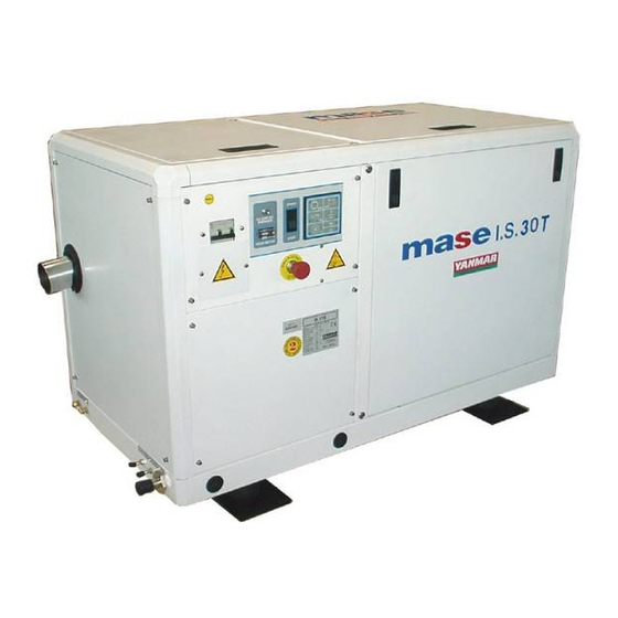
Mase IS 30 T Installation Manual
Marine generator
Hide thumbs
Also See for IS 30 T:
- Use and maintenance manual (25 pages) ,
- Use, maintenance and installation manual (94 pages)
Advertisement
Quick Links
Advertisement

Summary of Contents for Mase IS 30 T
- Page 1 IS 30 T 50 Hz INSTALLATION MANUAL...
- Page 2 IS 30 T Fig.1 Fig.2 Fig.3...
- Page 3 IS 30 T Fig.4 Fig.5 Fig.6 Valvola antisifone Anti-siphon valve Soupape antisiphon Beluchter Fig.8 Fig.7...
- Page 4 IS 30 T Fig.9 Fig.10 Fig.11 Fig.12...
- Page 5 IS 30 T Wiring diagram "STANDARD" version Fig.13...
- Page 6 IS 30 T Wiring diagram "RINA" version Fig.14...
-
Page 7: Table Of Contents
IS 30 T INDEX 1 GENERAL INFORMATION ........................20 1.1 Purpose and field of application of the manual ................20 1.2 Symbols ............................20 2 PRESCRIPTIONS FOR SAFETY DURING INSTALLATION AND SETUP ..........21 3 INSTALLATION ............................21 3.1 Characteristics of the installation space ..................21 3.2 Fastening the unit to the ground ...................... -
Page 8: General Information
WILL RESULT IN FORFEITURE OF THE GUARANTEE ON THE PRODUCT. 1.1 Purpose and field of application of the manual Thank you for choosing a mase product. This manual has been drawn up by the manufacturer with the purpose of providing essential information and instructions for proper installation in conditions of safety and constitutes an integral part of the generator equipment. -
Page 9: Prescriptions For Safety During Installation And Setup
Direct infeed system. mentioned conditions. System with baffle. mase recommends the direct infeed system, (Fig. 7, ref. 1), since this system prevents water under pressure entering the suction ducts and instead forms a pressure which can easily be overcome by the water pump of the electric generator. -
Page 10: Typical Installation With Generator Above The Waterline
IS 30 T 4.2 Typical installation with generator above the waterline If the unit is installed more than 1 m above the water- line, a check valve should be fitted after the sea intake, See Fig. 3 (Fig. 5, ref. 1), to prevent the water circuit emptying when Sea exhaust the motor is off. -
Page 11: Drainage System
IS 30 T 4.5 Drainage system 6 ELECTRICAL CONNECTIONS The flue gas/water drainage system of the generator must be separate from that of the main motors. 6.1 Battery connection To start off the unit an independent battery of 12 V is needed, capacity 100 Ah. -
Page 12: Ac Connection
IS 30 T 6.3 AC connection 6.4 Generator-mains switching To connect the power, disassemble the onboard A switch should be placed on the line to switch the user instrument panel, (Fig. 10, ref. 3); then run the power appliances from the generator to an external power line. -
Page 13: Wiring Diagrams
IS 30 T 8 WIRING DIAGRAMS 8.1 "STANDARD" version 8.2 "RINA" version See Fig. 13 See Fig. 14 Magnetothermal switch Magnetothermal switch Hour counter Hour counter Alternator Alternator Rotor Rotor Stator Stator Voltage regulator Voltage regulator Fuel leak light Thermal switch...


Need help?
Do you have a question about the IS 30 T and is the answer not in the manual?
Questions and answers