
Related Manuals for ACME theatre spot 150 TS-150 CW


Summary of Contents for ACME theatre spot 150 TS-150 CW
-
Page 1: User Manual
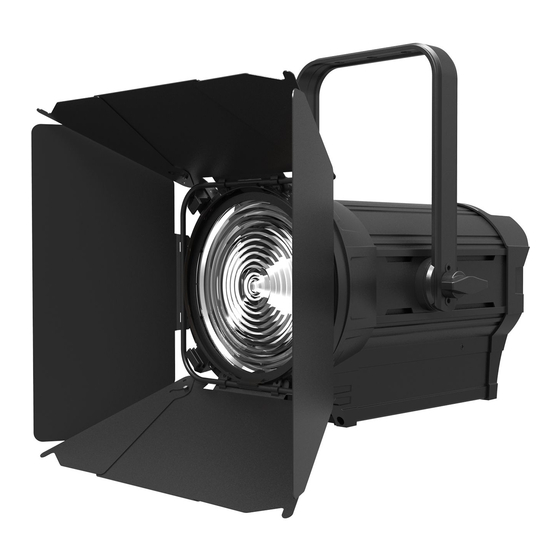
TS-150 CW TS-150 WW TS-1504 CW TS-1504 WW User Manual Please read the instruction carefully... -
Page 2: Table Of Contents
CONTENTS 1. Safety Instructions ................. 2 2. Technical Specifications ................. 3 3. The Plate for Color Filter & Barn Door Installation ......... 4 4. How To Set The Unit................5 4.1 Control panel ................... 5 4.2 Main Functions ................6 5. -
Page 3: Safety Instructions
1. Safety Instructions Please read the instruction carefully which includes important information about the installation, usage and maintenance. WARNING Please keep this User Guide for future consultation. If you sell the unit to another user, be sure that they also receive this instruction manual. ... -
Page 4: Technical Specifications
moisture. DO NOT open the unit within five minutes after switching off. The housing, the lenses, or the ultraviolet filter must be replaced if they are visibly damaged. Caution There are no user serviceable parts inside the unit. DO NOT open the housing or attempt any repairs yourself. -
Page 5: The Plate For Color Filter & Barn Door Installation
Power consumption: 190W Color Temperature: 5600+100K (TS-150 CW) 3150+100K (TS-150 WW) Light Source: 1 × 150W white LED CRI: ≥ 92 ≥ 89 Weight: 8.6Kgs Dimension: 406×417×238mm Photometric Diagram: Distance(m) ° ° ° 14 Lux 6920 2300 1175... -
Page 6: How To Set The Unit
○ At first, please push the Lock Cap button by hand as the arrow , and move away the Lock as the ○ ○ arrow ; Then insert the Plate for Color Filter into the inside slot from topside Fig. 2 ○... -
Page 7: Main Functions
1. Display: Show the various menus and the selected functions. 2. LED: MASTER Master Mode SLAVE Slave Mode DMX input present 3. Button: MENU To select the programming functions DOWN To go backward in the selected functions To go forward in the selected functions ENTER To confirm the selected functions 4. -
Page 9: Dmx Address
DMX Address Select DMX Address, press the ENTER button to confirm, the present address will blink on the display. Use the UP and DOWN button to adjust the DMX address from 1 to 512. Once the address has been selected, press the ENTER button to save. Hold and press the MENU button about one second or wait for one minute to exit the menu mode. -
Page 10: Slave Mode
Slave Mode Select Slave Mode, press the ENTER button to confirm, present mode will blink on the display. Use the DOWN and UP button to select the Master or Slave mode. Once the mode has been selected, press the ENTER button to save. Hold and press the MENU button about one second or wait for one minute to exit the menu mode. -
Page 11: Fixture Information
menu mode) or No (display always on), press the ENTER button to save. Press the MENU button back to the last menu or let the unit idle one minute to exit menu mode. Display Inverse Select Display Inverse, press the ENTER button to confirm, present mode will blink on the display, use the UP/DOWN button to select the No (normal display) or Yes (inverse display), press the ENTER button to save. -
Page 12: How To Control The Unit
show on the display. Press the MENU button back to exit. Firmware Version Select Firmware Version, press the ENTER button to confirm, the software version will show on the display. Press the MENU button back to exit. Factory Setting Select Factory Setting, press the ENTER button to confirm, present mode will blink on the display. Use the DOWN and UP button to select the No or Yes (Switch back to default settings). -
Page 13: Dmx 512 Configurations
when the display stops blinking or storing automatically one minute later. To go back to the functions without any change press the MENU button again. If you use please refer to the following diagram to address your DMX512 channel for the first 4 units. 2 channels:... -
Page 14: Troubleshooting
Inadequate or damaged cables, soldered joints or corroded connectors can easily distort the signal and shut down the system 2. The DMX output and input connectors are pass-through to maintain the DMX circuit when one of the units’ power is disconnected. 3. -
Page 15: Fixture Cleaning
damage or interference to DMX interface circuit. C. One of the channels is not working well 1. The stepper motor might be damaged or the cable connected to the PCB is broken. 2. The motor’s drive IC on the PCB might be out of condition 8. - Page 16 D eclaration of Conformity We declare that our products (lighting equipments) comply with the following specification and bears CE mark in accordance with the provision of the Electromagnetic Compatibility (EMC) Directive 89/336/EEC. EN55103-1: 2009 ; EN55103-2: 2009; EN62471: 2008; EN61000-3-2: 2006 + A1:2009 + A2:2009; EN61000-3-3: 2008. &...
Need help?
Do you have a question about the theatre spot 150 TS-150 CW and is the answer not in the manual?
Questions and answers