Table of Contents
Advertisement
Quick Links
Download this manual
See also:
User Manual
Advertisement
Table of Contents

Related Manuals for Intellinet IBC-667IR


Summary of Contents for Intellinet IBC-667IR
- Page 1 IBC-667IR Network Bullet Camera Hardware Installation Guide...
-
Page 2: Package Contents
Package Contents Camera Network Bullet Camera Quick Installation Guide Brief product information and quick installation Software CD IP Surveillance Software Intelligent IP Installer User Manuals Language Packs Accessories - Wall mount bracket & U-shape bracket - Metal plate for wall mount bracket - Alignment Sticker - Waterproof Connector - Screw pack for sun shield &... -
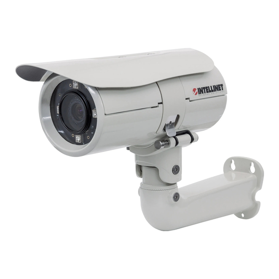
Page 3: Hardware Description
Hardware Description IR LED Lens Light Sensor ... -
Page 4: I/O Terminal Block Circuit
I/O Terminal Block Circuit Digital Input 1/2: Max: 30V DC Digital Output 1/2: Max: 24V / 100mA I/O Terminal Block Pin Definition Definition Description Max. V/A Ground 12V DC + 12V DC 1.2W Unbalanced, 1.4Vp-p, 1Vrms, terminal block AUDIO_In(+) AUDIO_Out(+) Unbalanced, 1.4Vp-p, 1Vrms, terminal block Uses an NPN transistor with the emitter connected to the 100 mA GND pin. -
Page 5: Led Indicators
LED Indicators Color Indication Green Active network link Network Orange Flashing indicates network activity Steady red during boot-up process Blue Steady blue when boot sequence has been completed Power When the reset button was pressed for at least 5 sec. Unlit and camera is restarting, Steady orange means SD card ready... -
Page 6: Installing The Hardware
Installing the hardware 1) Assembling sun shield and camera with two supplied screws(M3*6). 2) Fix U-shape bracket to the bottom of camera with supplied screws. 3) Insert all cables (RJ45/power cord/DIDO) into waterproof connector (M25*1.5). 4) Open the front cover and feed all cables through the screw hole of bottom cover from outside. -
Page 7: Wall And Ceiling Mounting
Wall and Ceiling mounting Attached the alignment sticker to the wall. Drill four holes into the wall. Three holes are for the screws to affix the bracket to the wall, and one larger hole for the cable. Push the supplied plastic anchors into the screw holes and secure the plate with the supplied screws (T1/4”*32). -
Page 8: Factory Reset
Factory Reset Reset: With the camera turned on, press the reset button briefly to reboot the camera, or hold the reset button for 10 seconds to set all settings back to factory default values. 1. Connect the camera via PoE Using a standard RJ-45 network cable, connect the bullet camera to an IEEE802.3af/at compliant PoE switch or PoE injector. - Page 9 INTELLINET NETWORK SOLUTIONS™ offers a complete line of active and passive networking products. Ask your local computer dealer for more information or visit www.intellinet-network.com Copyright © INTELLINET NETWORK SOLUTIONS All products mentioned are trademarks or registered trademarks of their respective...
Need help?
Do you have a question about the IBC-667IR and is the answer not in the manual?
Questions and answers