Table of Contents
Advertisement
Quick Links
Advertisement
Table of Contents

Related Manuals for Intellinet 503792


Summary of Contents for Intellinet 503792
-
Page 1: User Manual
SOHO NETWORK CAMERA USER MANUAL MODEL 503792 INT-503792-UM-0808-01... -
Page 2: Table Of Contents
Contents Introduction......................1 Package Content....................1 System Requirement..................... 1 Hardware Installation..................... 2 4.1. LED and Focusing ....................2 4.2. Camera Ports....................3 4.3. Installation Procedure ..................4 Software Installation ....................5 Using the Administrator Utility ................11 6.1. General Setting....................12 6.2. Detail Setting ....................14 6.2.1. - Page 3 8.3. WLAN ......................62 8.4. E-Mail and FTP....................64 8.5. Motion Detection .....................66 8.6. System......................67 8.7. Status......................68 8.8. Users ......................69 8.9. Log........................70 Frequently Asked Questions ..................71 Technical Specifications..................72 10. Appendix A Router/Gateway Setup for Internet Viewing ........73 11. Appendix B Set up WLAN step by step .............. 75 12.
-
Page 4: Introduction
Introduction Thank you for choosing the INTELLINET NETWORK SOLUTIONS SOHO Network Camera. This SOHO Network Camera sends live video through 10/100 Mbps wired network to a web browser or camera viewer across Internet anywhere in the world! This compact, self-contained unit lets you keep an eye on your home, your kids, and your workplace—whatever’s important to you. -
Page 5: Hardware Installation
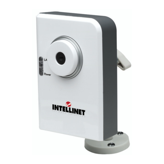
Hardware Installation 4.1. LED and Focusing The Camera head and its focus ring allow you to modify the aim and focus of the Camera. To adjust the Camera’s focus, rotate the dark focus ring. There are four LEDs indicating the camera status and networking status. Power When the camera is power on, the LED will light. -
Page 6: Camera Ports
4.2. Camera Ports The Camera features three ports and a Reset button. Power The Power port is where you can connect the power adapter. The LAN port is where you can connect the Ethernet network cable. WLAN (Antenna Connector) This round connection is standard Reverse SMA connector where any antennas with Reverse SMA connector can connect to the SOHO Network Camera.. -
Page 7: Installation Procedure
4.3. Installation Procedure 1. Unpack the SOHO Network Camera package and verify that all the items listed in Chapter 2 are provided. 2. Connect the SOHO Network Camera to your network by attaching the network cable from the switch/router to the UTP port of the SOHO Network Camera. 3. -
Page 8: Software Installation
Software Installation Follow the simple steps below to run the Install Wizard to guide you quickly through the Installation process. The following installation is implemented in Windows XP. The installation procedures in Windows 2000/Server 2003 and Vista are similar. 1. Insert the CD shipped along with the SOHO Network Camera into your CD-ROM drive. The “Autorun.exe”... - Page 9 3. The system will start the installation procedures. Click “Next” to continue installation. 4. If you wish to install the software program in an alternate location, click “Change”; otherwise click “Next” to move on to the next step.
- Page 10 5. Click “Install” to start installing the program. 6. The system will install the program automatically.
- Page 11 7. Click “Finish” to complete the software installation. 8. ”Administrator Utility“ will be run automatically after installation. On the SOHO Network Camera first page, the cameras found in the network are listed in the left window. Choose the one you want to configure and click “Setting Wizard” to proceed. “N”...
- Page 12 9. Please enter the default password “1234” and click “OK” to login to the IP setup page. 10. SOHO Network Camera is working through the network (TCP/IP Protocol). The IP address and subnet mask setting must be correct, or you cannot access to the camera. The wizard program will detect the IP address status of your network automatically and suggest a free IP address for the Camera.
- Page 13 12. The “Camera Viewer” will show the video automatically. Congratulations, you can use the camera through the network to view the video from now on.
-
Page 14: Using The Administrator Utility
Using the Administrator Utility The Administrator Utility allows users to search and setup the cameras located within the Intranet or on the Internet. From the utility, users can view all the information of the selected camera; furthermore, it provides a setting wizard, which can guide users to add the camera to the network easily and promptly. -
Page 15: General Setting
6.1. General Setting Auto Discover Click the button will search the camera within the network. Camera List The list shows the camera name and the setup status of the camera. It means the camera is in the default setting. It means the camera is configured before. Internet Click “Add”... - Page 16 It means the camera is disconnected or not in the Internet. It means the camera is connected. Information of Camera Camera Information It displays all information of the selected camera. The information includes Firmware Version, Network Information, IP Address, UPnP Setting, DDNS Setting, Resolution and E-mail setting, etc. Camera Setting Detail Setting Click “Detail Setting”...
-
Page 17: Detail Setting
6.2. Detail Setting When you click the “Detail Setting”, a screen will pop up for you to enter the “Administrator Name” and “Password”. The default value is as follows. Name: “Admin” Password: “1234” If the name and password you enter are correct, you can start to setup the camera. -
Page 18: Network Setting
6.2.1. Network Setting Network Setting SOHO Network Camera The default camera name is “IC1500WG”. It is recommended to Name name a meaningful name for the camera. IP Address Enter an unused IP Address within the IP address range used on your LAN. -
Page 19: Wireless Settings (*Wireless Model Only)
same with the gateway used by the PCs on your LAN. DNS Server DNS Server (Domain Name Server) that translates names to IP addresses. Set the same DNS Server as the PCs on your LAN. Network Setting Video Port The Video Port is used to transmit or receive the video streaming in the network. - Page 20 Utility will site survey automatically or you can press “Refresh” button to survey the AP router manually. After site survey procedure, there will show existing AP SSID. Then press “Connect” to connect AP router or press “Add to Profile” to configure the Wireless WEP and WPA encryption.
- Page 21 There are WEP(Open System/Shared Key) ,WPA-PSK,WPA2-PSK and WPANone encryption settings. You can choose one to match AP router wireless settings. After set the profile, Please remove the LAN cable then IP Camera will connect to AP router automatically. LED Status Diagram Wired Setting Environment Wireless Setting Environment You must configure the wireless settings from wired environment.
-
Page 22: E-Mail Setting
6.2.3. E-Mail Setting E-Mail Settings Recipient E-Mail Address This camera supports “Snap Shot” and “Motion Detection” functions. You can snapshot a picture and send the picture by E-Mail. Enter the E-Mail Account for receiving the picture. SMTP Server Enter the SMTP Server for the E-Mail sending. Sender E-Mail Address Specified the e-mail address of the e-mail sender. -
Page 23: Pppoe Settings
Send a Test Email Press this button to send a test e-mail to your mailbox. You can use this function to test if your setting is correct. 6.2.4. PPPoE Settings PPPoE Settings Enable/Disable If enable the PPPoE function, IP Camera will use PPPoE for network connection first. -
Page 24: Ftp Settings
6.2.5. FTP Settings FTP Settings FTP Server This camera supports “Motion Detection” functions. When Motion Detection event occurred, you can record the pictures to FTP server. Enter the FTP address for receiving the pictures. FTP Port Enter the port of the FTP server. User Name Specify the user account of ftp server. -
Page 25: Date / Time Settings
6.2.6. Date / Time Settings Date / Time Settings Set Date/Time manually Set the current Date and Time. NTP Server Synchronize the Date and Time with NTP server. Time Zone Select the time zone that your camera put on. NTP Server Specify the IP Address of the NTP Server. -
Page 26: Resolution
6.2.7. Resolution Resolution Resolution Select the desired video resolution format. Larger resolution requires more bandwidth. 640 x 480 is “VGA” format. 320 x 240 is “CIF” format. 176 x 144 is “QCIF” format. -
Page 27: Advanced Setting
6.2.8. Advanced Setting Advanced Settings UPnP When the UPnP function is enabled, the camera can be detected by UPnP compliant system such as Windows XP. The camera will be displayed in the Neighborhood of Windows XP, so you can directly click the camera to view the video through web browser. DDNS Many internet connections use a "Dynamic IP address", where the Internet IP address is allocated dynamically whenever the... -
Page 28: Users
Enable/Disable Enable or disable DDNS function of the camera. Provider Several companies provide DDNS service. This camera supports the service from DynDNS who is one of the DDNS providers. Domain Name The domain name given by DynDNS is “registername.dyndns.com”. Enter the domain name that you register for the camera from DynDNS web site. -
Page 29: Tools
Current Password Enter the current password of the camera. New Password Enter the new password you want to use for the camera. Confirm New Password Retype the new password to confirm the setting. User Setting the user account and password. Your camera can support 4 user account. -
Page 30: About
Tools Firmware Version Display current firmware version. Firmware Update You can upgrade camera’s firmware via this function. Press this button and select the correct firmware to upgrade. Reset to Default If you want to reset the camera, click this button. The default settings of the camera are as follows. -
Page 31: Setting Wizard
About Administrator Utility Display current Administrator Utility Version. Version 6.3. Setting Wizard When you click the “Setting Wizard”, a screen will pop up for you to enter the “Administrator Name” and “Password”. The default value is as follows. Name: “Admin” Password: “1234”... - Page 32 IP Address The wizard will auto setup an available IP Address to the camera. For example: if the IP address of the network is 192.168.2.x, the wizard will search an unused IP Address from 192.168.2.1 to 192.168.2.250 and assign the camera an available IP Address. You are allowed to enter another IP Address to change the setting.
-
Page 33: Installing The Ip Camera Surveillance Software
Installing the IP Camera Surveillance Software 1. Double-click the setup file located on the supplied CD-ROM. When the following window appears, click "Next." 2. You can specify the destination folder of the software installation or you can just use the default folder, and click "Next"... - Page 34 3. If you want the installation program to create a desktop icon or a quick launch icon for you, select the desired items and click "Next" to continue. 4. The next screen presents a summary of the installation options. Click "Install" to begin the installation process.
-
Page 35: Using The Ip Camera Surveillance Software
5. After the installation has finished, the following screen appears: Click "Finish" to complete the installation. 7.1. Using the IP camera surveillance software You can click the "IPCam Surveillance Software" icon from the desktop, quick launch bar, or start menu to start the IP camera surveillance software. Before you start: IP camera surveillance software will only work when your monitor’s resolution is "1024 x 768". - Page 36 Here are descriptions for all components of the IP camera surveillance software: Video display area Language Display layout Full screen / Scan Zoom Out / Zoom In PTZ Control / Home Message display Recording / System configuration Playback / Snap shot EXIT Program Below is a description of the buttons and their functions.
- Page 37 "ESC" key to return to the normal mode. Scan Click this button once to activate scan function (scan icon will become blue ); click again to stop scanning (scan icon will become white Zoom out Zoom-out This function is only available for supported cameras. The SOHO Network Camera does not support this function.
-
Page 38: Configure The Ip Surveillance Software
Video display Displays the image of all cameras by the display layout you area have selected. 7.2. Configure the IP Surveillance Software 1. Configure cameras Before you use this IP camera surveillance software, you must configure the camera(s) you wish to connect. Click the "System configure" button and a popup menu will appear: Select ‘Configure Cameras’: Note: If you’re prompted by a windows security alert which asks you if you... - Page 39 2. Camera tab On this tab you can configure all cameras you wish to connect. Up to 16 cameras can be connected simultaneously:...
- Page 40 Here are the descriptions of all setting items: Item Description Channel Select the channel number you wish to set. Camera Search All cameras found on your local network will be displayed in the "Camera Search" box. Select Select a camera listed in the "Camera Search" box, and click ‘Select’...
- Page 41 After you’ve set all channels you wish to set, click "OK" to save the settings. If everything’s correct, you’ll see the camera’s image in the IP camera surveillance software’s main menu:...
- Page 42 3. Schedule Recording tab On this tab, you can set up a scheduled video recording, so you can record the video captured by all cameras you have by a pre-defined schedule. Find a description of all options on the next page:...
- Page 43 Item Description Channel Select the channel number you wish to set. One Time You can specify the one-time schedule for a selected camera; Schedule this schedule will be executed once only. Click this button and a new window will appear: (One Time Schedule) Specify the time duration of this one-time schedule (the date...
- Page 44 Delete Delete a selected schedule item. Save settings on this tab. Cancel Discard all settings on this tab. 4. Audio tab This menu has no function, as the 503792 SOHO Network Camera does not support audio.
- Page 45 5. Motion Recording tab With this function activated, only motion captured by the camera will be recorded, so you don’t have to waste hard disk storage space on images you don’t need to pay attention to. WARNING: This function should not be used to secure high-value items. Good-quality alarm sensors, e.g., IR based, will provide more reliable results.
-
Page 46: General Settings
7.3. General Settings This menu gives you access to important settings of the 16-channel viewer. 1. General tab Item Description Data Directory Set the directory (folder) you wish to store the recorded video and captured image. Click "Browse" to select a directory. Free Recording Displays the remaining storage space on the drive where the Space... - Page 47 2. E-Mail Setting tab If you want to use the motion detection function and wish to get an e-mail that contains the image captured by the camera, set up your e-mail-related parameters here first. Find explanations about the options on the next page.
- Page 48 Item Description E-Mail Subject Specify the subject of the e-mail. Recipient E-Mail All e-mail addresses you set. Address Click this button and you’ll be prompted to input the e-mail address. Click "OK" to save changes. Edit Select an e-mail address from "Recipient E-Mail Address" box, and click "Edit"...
- Page 49 3. Security tab If you don’t want other people to access the SOHO Network Camera surveillance software, you can set a password to protect it. You’ll need to input the password every time you wish to use this IP camera surveillance software. The image below shows the password request window.
- Page 50 4. About tab The software version is shown here. Be sure to write down the number and have it handy before contacting the technical support team.
-
Page 51: Change Display Layout
7.4. Change Display Layout This IP camera surveillance software provides eight different layout styles. They are selectable via the control panel shown below: Each of the designs displays a different amount of cameras. In order to get a full-screen view of a camera, click on the button as indicated below. - Page 52 Layout style 1: 1 Displays the video of 1 camera only. Camera only Layout style 2: 4 Displays the video of up to 4 cameras. Cameras Layout style 3: 6 Displays the video of up to 6 cameras. Cameras Layout style 4: 8 Displays the video of up to 8 cameras.
- Page 53 Layout style 5: 9 Displays the video of up to 16 cameras. Cameras Layout style 6: Displays the video of up to 10 cameras. 10 Cameras Layout style 7: 13 Displays the video of up to 13 cameras. Cameras Layout style 8: 16 Displays the video of up to 16 cameras.
-
Page 54: Scan Function
7.5. Scan function With this function you can periodically switch between the cameras that are set up in the software. The scan interval is defined in the general options. Click the scan button once to activate the scan function (the scan icon will become blue );... -
Page 55: Zoom And Ptz Controls
7.6. ZOOM and PTZ Controls These functions are not supported by the SOHO Network Camera Model 503792. Don't be surprised if nothing happens when you click on any of these buttons. Zoom in/out PTZ Control... -
Page 56: Snapshot
7.7. Snapshot You can take a snapshot of the selected camera by clicking the designated button shown below. The snapshot images are saved in the data directory of the camera viewer as defined in the General Options section. 7.8. Recording Click the button showing the video camcorder below to start the recording process. -
Page 57: Playback
7.9. Playback You can play back all recorded video by clicking this button. A new window will appear: You have to locate the video file before you can play it. There are two ways of doing this: Time Search (search all video files which fall within a specific time period) and Motion Search (search all video files recorded by the motion detection function which fall in a specific time period). -
Page 58: Web Connection And Setup
Web Connection and Setup You can use the Web browser to connect the camera for viewing or setting. Open the web browser and enter the IP Address of the camera to establish a connection. The default IP Address of the camera is “192.168.2.3”. When the welcome screen appears, enter the “Admin Name”... - Page 59 the video image will be shown up in the web screen directly. After installed the ActiveX plug-in, The menu options for the web control screen are as follows. Camera – View live video and adjust the video format from the menu. LAN –...
-
Page 60: Camera Setting
8.1. Camera Setting Camera Setting Resolution Select the desired video resolution format. Larger resolution requires more bandwidth. 640 x 480 is “VGA” format. 320 x 240 is “CIF” format. The default resolution is CIF format. Image Quality Adjust this property to control the video quality Max Frame Rate Set the video max frame rate. - Page 61 be from 1 to 100. You can adjust the hue by change the value. This value can be from 1 to 100. Whiteness You can adjust the white balance by change this value. This value can be from 10 to 30. Enable Auto Exposure You can enable Auto Exposure by check this box.
-
Page 62: Lan Setting
8.2. LAN Setting Network Type This camera can obtain IP via DHCP protocol or specified static IP Address to it.. IP Address Enter an unused IP Address within the IP address range used on your LAN. If the IP Address of your LAN is from the 192.168.2.0 to 192.168.2.250, you can set an unused IP Address from the range for the camera, for example: 192.168.2.250. - Page 63 same with the gateway used by the PCs on your LAN. DNS Server DNS Server (Domain Name Server) that translates names to IP addresses. Set the same DNS Server as the PCs on your LAN. Video Port The AV Control Port is used to transmit or receive the AV streaming in the network.
- Page 64 Domain Name The domain name given by DynDNS is “registername.dyndns.com”. Enter the domain name that you register for the camera from DynDNS web site. User Name Enter the login name for the DDNS service. Password Enter the password for the DDNS service. Apply When you finish the “Dynamic DNS”...
-
Page 65: Wlan
8.3. WLAN Wireless Setting Wireless connection Enable or disable the wireless function of the SOHO Network Camera. By default, the function is disabled. Network Type Infrastructure – This operation mode requires the presence of a Wireless LAN Access Point or Router. All communication is done via the Access Point or Router. - Page 66 merging of two co-located WLANs. You may specify a SSID for the card and then only the device with the same SSID can interconnect to the card. If you want to add one of the networks nearby to the profile list, pull down the menu, all the networks nearby will be listed and you can add one of them to the profile list.
-
Page 67: E-Mail And Ftp
Key1 ~ Key4 The WEP keys are used to encrypt data transmitted in the wireless network. Fill the text box by following rules below. 64-bit – Input 10-digit Hex values (in the “A-F”, “a-f” and “0-9” range) or 5-digit ASCII characters (including “a-z” and “0-9”) as the encryption keys. - Page 68 AV Server Recipient E-Mail Address This camera supports “Motion Detection” function. Enter the E-Mail Account for receiving the pictures. SMTP Server Enter the SMTP Server for the E-Mail sending. Sender E-Mail Address Specified the e-mail address of the e-mail sender. SMTP Authentication Enable or Disable the SMTP Authentication function Username...
-
Page 69: Motion Detection
8.5. Motion Detection The “Motion Detection” allows users to setup the behavior of motion detection feature. Motion Detection Motion Detection Enable Enable or Disable the Motion Detection Function. Next Event Detected Setup the interval between two events. For example, if you setup Interval the interval to 5 seconds, the next event will start after this event finished + 5 seconds. -
Page 70: System
8.6. System The “System” allows users to setup the camera’s parameters, like camera name, data/time setting. And also provide firmware upgrade and reset tools at this page. System Camera Name The default camera name is “IC1500”. It is recommended to name a meaningful name for the camera. -
Page 71: Status
NTP Server Synchronize the Date and Time with this NTP server. Time Zone Select the time zone that your camera put on. NTP Server Specify the IP Address of the NTP Server. Upgrade Firmware You can upgrade camera’s firmware via this function. Press the browse button, find the correct firmware and press upgrade. -
Page 72: Users
8.8. Users The “Users” allows users to add four user accounts which are able to view video from Camera Viewer and Web Management. These users, unlike Administrator, are not allowed to configure the camera. -
Page 73: Log
User 1 / 2 / 3 / 4 User # Enable or Disable the user number #. Login Enter the the login name to the camera. Password Enter up to 4 digits password for the new user account. Confirm Password Enter the password again to confirm the setting. -
Page 74: Frequently Asked Questions
Log screen The screen will show event and event time of device. Refresh You can press “Refresh” button to refresh the log screen. Frequently Asked Questions Q1: What is an SOHO Network Camera? A: The SOHO Network Camera is a standalone system connecting directly to an Ethernet or Fast Ethernet network. -
Page 75: Technical Specifications
Q3: Can I capture or record still images from the SOHO Network Camera? A: Yes, you are able to capture or record still images with the snapshot function from the Camera Viewer application supplied with the SOHO Network Camera CD-ROM. Q4: What network cabling is required for the SOHO Network Camera? A: The SOHO Network Camera uses Category 5 UTP Twisted-pair cable allowing 10 Base-T and 100 Base-T networking. -
Page 76: Appendix A Router/Gateway Setup For Internet Viewing
Frame rate: 30fps@QVGA, 20fps@VGA Video resolution: 176 x 144, 320x240, 640x480 System Hardware LAN Connector: One RJ-45 port to connect to 10/100Mbps Ethernet Wireless: IEEE 802.11b/g(*Wireless Model Only) LED Indicator: LAN LED (Green), WLAN LED (Amber), Power LED (Blue) Power Supply: 12V / 1A (Wireless Model) Power Supply: 12V / 0.4A (Wired Model) HTTP/Utility Includes easy-to-use Viewer &... - Page 77 Router/Gateway Port Forwarding/Virtual Server Setup Name Protocol Port LAN IP Setup 1 192.168.2.3 Setup 2 4321 192.168.2.3 Port Definition Setup 1 It is the port of Web port. You have to configure the protocol to “TCP”. Setup 2 It is the port of Video port. You have to configure the protocol to “TCP”.
-
Page 78: Appendix B Set Up Wlan Step By Step
Appendix B Set up WLAN step by step Please follow the procedures below: Please Check you Router Wireless settings, Suggesting Open System ( Disable security ) first. - Page 80 Please turn on DHCP Server of the Router for this testing.
- Page 81 Please reset the Wireless IP Camera settings to Factory Defaults by press the Reset button over 8 seconds. Please change your PC’s IP address to 192.168.2.xx (which xx from 10 to 253), Netmask = 255.255.255.0 Please go to Web-Config WLAN section of the Wireless IP Camera. Press Refresh button until you find the SSID you want in the list first! Then select the Connect column of the SSID you want and select the Enable button of Wireless Connection.
- Page 82 Please go to the LAN section of Web-Config. Select DHCP and press Apply button. Then you could close this IE browser window now. Please UNPLUG the Ethernet Cable of the Wireless IP Camera now! Wait for seconds then the Wireless IP Camera should be linked with the Wireless Router.
- Page 83 Now you could let your PC to be connected with the Wireless Router. (10) In this case, if your PC’s DHCP Client IP is 192.168.8.101, then the Wireless IP Camera must be 192.168.8.100, because Wireless IP Camera was got IP early then your PC. (11) You could go to the Web-Interface of the Wireless IP Camera.
-
Page 84: Appendix C Viewing Via Upnp In Windows Xp
Appendix C Viewing via UPnP in Windows XP When the UPnP function is enabled, the camera can be detected by UPnP compliant system such as Windows XP. The camera will be displayed in the Neighborhood of Windows XP, so you can directly double click the camera or right click the camera and select “Invoke” to view the video through web browser. - Page 85 Enable UPnP in Windows XP SP2 If you can’t find the camera in the Neighborhood of Windows XP SP2 or you have seen the following message when you double click the camera. You have to check if UPnP function is blocked by the firewall.
- Page 86 4. The “Windows Firewall” screen will be popped up, select “Exceptions” option menu.
-
Page 87: Appendix D Configure Windows 2003 Server
5. Enable “UPnP Framework” from the “Programs and Services list” and click “Ok”. Appendix D Configure Windows 2003 Server Graphics Hardware Acceleration and DirectX are disabled by default on a Server configuration to ensure maximum stability and uptime. But for any reason you need to enable them to use DirectX enabled applications this section will guide you through on how you can do it. - Page 88 Simply right click anywhere on your desktop and select Properties -> Settings tab -> Advanced -> and finally, the Troubleshoot tab. Now move the Hardware acceleration slider across to Full Click OK You may experience a monitor black out for a few seconds, this is normal. Enabling DirectX...
- Page 89 go to Start -> Run -> and type dxdiag followed by enter. You will get a dialog box asking if you want to allow dxdiag to access the internet to check for valid WHQL certificates - click on Yes. Let's click on the Display tab, now click on all three boxes to enable DirectDraw, Direct3D and AGP Texture Acceleration.
- Page 90 INTELLINET NETWORK SOLUTIONS™ offers a complete line of active and passive networking products. Ask your local computer dealer for more information or visit www.intellinet-network.com Copyright © INTELLINET NETWORK SOLUTIONS All products mentioned are trademarks or registered trademarks of their respective owners.
Need help?
Do you have a question about the 503792 and is the answer not in the manual?
Questions and answers