Table of Contents
Advertisement
Quick Links
Advertisement
Table of Contents

Related Manuals for Intellinet PRO SERIES


Summary of Contents for Intellinet PRO SERIES
-
Page 1: User Manual
PRO SERIES Network Camera & Video Server USER MANUAL INT-PSNC-UM-1106-06... -
Page 2: Table Of Contents
Table of Contents Safety and Regulatory Notices ....................3 Section 1: Product Overview 1.1 About the Pro Series Network Cameras and Video Servers........... 5 1.2 Main Features and Benefits ................... 5 Section 2: Physical Description 2.1 Package Contents ......................6 2.2 MPEG4 CCD Camera..................... -
Page 3: Safety And Regulatory Notices
Appendix I: Glossary of Terms ....................93 Appendix J: Product Specifications…………………………............95 Thank you for purchasing this INTELLINET NETWORK SOLUTIONS™ Pro Series Network Camera or Network Video Server. This user manual includes instructions for using and managing the camera on your network. Networking experience will be helpful when setting up and using this product. -
Page 4: Important Notices
1. Camera surveillance laws may differ for each country. Contact the local authorities to avoid any surveillance law violations. 2. Note that the CCD lens that comes with the Pro Series Network Camera can be damaged permanently if exposed to direct sunlight. If your application demands prolonged exposure to sunlight, you should consider equipping it with a sun visor. -
Page 5: About The Pro Series Network Cameras And Video Servers
1.2 Main Features and Benefits Convenient Operation The Pro Series Network Camera does not need any additional software or interaction with any other server. The only software needed is a common Web browser, such as Microsoft Internet Explorer 5.x or above. -
Page 6: Package Contents
Multi-Viewer, etc. Power Supply AC power adapter and power cord Stand Wall & table stand* Connection RS-232 cable Cable User Manual Hard-copy book * You can use a standard camera stand or tripod for the Pro Series (MPEG4) Network Camera. -
Page 7: Mpeg4 Ccd Camera
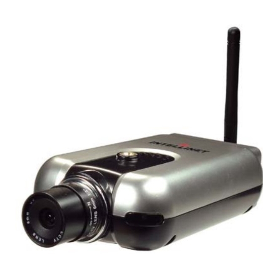
2.2 MPEG4 CCD and CMOS Camera Front View Power LED Network Activity LED Operating Status LED Power LED (Red): Once power is supplied to the camera, the red LED will light. Operating Status LED (Green): This LED indicates the camera’s operating status. Once power is supplied, the LED lights and then blinks once every second as long as the video is transmitted on the network during normal operation. -
Page 8: Mpeg4 Ccd Ir Camera
MIC. NOTE: The Pro Series Network Camera is compatible with 3.5mm stereo microphones. If you are a 3.5mm mono microphone user, use the included 3.5mm stereo plug to two 3.5mm mono jack converter. -
Page 9: Network Video Server
2.4 Network Video Server Video Input: To input video signal through a coaxial cable Video Output: To output video signal through a coaxial cable. Video Input Video Output On Air Network LED Power LED On Air LED (Green): This LED indicates the Video Servers operating status. Once power is supplied, the LED lights and then blinks once every second as long as the video is transmitted on the network during normal operation. -
Page 10: Vandal-Proof Dome Camera
I/O Connector: To connect external devices such as infrared sensors, alarms or motion detectors (refer to Appendix F: I/O Connector). Ethernet (Network Connector): Connect 10Base-T Ethernet or 100Base-TX Fast Ethernet cable. SPK: Use to connect to an external speaker for audio communication. The audio sent over the network from a connected Video Server client can be delivered through this externally connected speaker. -
Page 11: Jpeg Cmos Camera 550710
Rear View Terminal Block 6-pin input/output for external alarm devices and sensors RJ-45 Network Connector IEEE802.3af PoE-compliant network connector. Power connector 12 V DC power input for non-PoE installations. BNC Loop-through port Analog video output signal for CCTV systems and monitors. -
Page 12: Section 3: Installation Summary And Examples
Appendix F for details. 3: Installation Summary and Examples 1. Connect the Ethernet and power to the Pro Series Network Camera. 2. Install and launch the IP Installer program on the enclosed CD. 3. Assign an IP address and network settings. - Page 13 Installation Example: Wireless Camera Installation Example: Network Video Server...
-
Page 14: Connecting The Camera To A Pc
4: Assigning an IP Address and Accessing the Camera’s Homepage 4.1 Connecting the Camera to a PC Connect with a direct cable (non-crossover UTP cable) when connecting the camera to a switch, hub or router. Connect with a crossover UTP cable when connecting the camera to a PC. -
Page 15: Setting Up The Ip Address Using Ip Installer
2. Once IP Installer is run, the panel shows every camera connected on the local network. From the cameras listed, select one to assign a new IP address (every Pro Series Network Camera has a factory default IP address). NOTE: The MAC address can be found on the underside label of the camera. -
Page 16: Accessing The Camera's Homepage
- Opera (Java) - Konqueror (Java) The INTELLINET NETWORK SOLUTIONS Pro Series Network Camera supports two connection methods: ActiveX for Microsoft's Internet Explorer users on Windows systems; and Java for all other Web browsers and operating systems, including MacOS and Linux, and Windows when using a different Web browser than MS Internet Explorer. - Page 17 MS Internet Explorer – JPEG Stream Mode Both options, ActiveX and Java, are available in this operational mode. If you can run and install ActiveX controls, you should select ActiveX as your preferred viewing program, as it offers higher frame rates and better functions. MS Internet Explorer –...
- Page 18 Non-MS Internet Explorer – MPEG4 Stream Mode Java is the only choice given, but the warning message tells you that even though you are able to login you won't be able to see the live image. You still can access the administration menu to make changes to the settings.
- Page 19 ActiveX Installation for MS Explorer Users (automatic) The first time you login to the camera using ActiveX, you are notified that a required plug-in / ActiveX control is required. You need to allow the installation of ActiveX by clicking "Yes" to the question "Do you want to install the program?"...
- Page 20 Click "Next" to continue with the installation. When you see the message above, you have successfully installed the ActiveX control. Restart MS Internet Explorer and re-connect to the camera.
- Page 21 4.4 Homepage Options (MPEG4 Cameras) Once the login procedure is complete, you can view the Pro Series (MPEG4) Network Camera homepage. Below is an overview of the different pages for the different models for both Java and ActiveX. MPEG4 CCD Cameras - Java version...
- Page 22 MPEG4 CMOS Cameras with Digital Pan Tilt Zoom - ActiveX version Video Size You can select a viewing image size from 0.5 to 2. This function represents a digital zoom. It does not change the physical resolution of the image. At high resolution (D1) the options "x1.5" and "x2"...
- Page 23 Record Video Users can save real-time images from the camera on a PC. Click "Start," then select the folder to save the images in. (The image is saved as an AVI file.) Once the camera starts to save images, the green LED indicator will start blinking. To stop saving, click "Stop" and the LED indicator will stop blinking.
-
Page 24: Homepage Options (Jpeg Cmos Camera 550710)
4.5 Homepage Options (JPEG CMOS Camera 550710) The camera homepage of the 550710 camera looks different than the screens of the other models; however, most functions work the same. Expansion You can select a viewing image size from 0.5 to 2. This function represents a digital zoom. It does not change the physical resolution of the image. -
Page 25: Adjusting The Focus
5.2 Replacing the Lens The Pro Series Network Camera is designed with a CS mount. The lens supplied with your product can be replaced with any standard C or CS lens, typically used within the surveillance industry. Follow the instructions below to replace the supplied lens with any C- or CS-type lens. -
Page 26: Overview Of The Administrator Menu
6: Administrator Menu You can control the configurations of the camera using the administrator tools, which can be accessed only by an authorized user. If non-authorized users try gaining access, you may see a warning message "You are not an administrator." 6.1 Overview of the Administration Menu The table below provides a one-step overview of the Administrator Tools: Image Configuration... -
Page 27: Image Configuration
6.2 Image Configuration 6.2.1 MPEG4 CCD Cameras, Dome Cameras and Network Video Server Rate Control The bit rate used in video encoding has a direct impact on the video quality and the bandwidth used to stream video over the network. As opposed to constant bit rate (CBR), VBR files vary the amount of output data per time segment. - Page 28 Lowest Bit Rate/Quality -> smallest network bandwidth usage Above image illustrates the effects of lowering the video quality. You have full control over the amount of bandwidth the camera can use, to the point where it becomes difficult to identify any objects in the image due to heavy compression damage.
- Page 29 Resolution Select the resolution for output video. Pro Series CCD Network Cameras support three types of image resolution. NTSC: D1 (720x480), VGA (640x480) and CIF (352x240); PAL: D1 (720x576), VGA (640x576) and CIF (352x288). The Digital PTZ CMOS camera supports 720x480, 640x480, 352x240 and 320x240 pixel image resolution.
- Page 30 De-Interlace Interlaced video is composed of two fields that are captured at different moments in time. When displayed on a typical computer screen, interlaced video frames will exhibit motion artifacts when both fields are combined and displayed at the same moment (today's computer screens are progressive scan monitors which display the image line by line from top to bottom without interlacing).
- Page 31 Most sources of visible light contain energy over a band of wavelengths. Hue is the wavelength within the visible-light spectrum at which the energy output from a source is greatest. Normally there is no need to change the default value (8), but if you wish to experiment with different hue values to achieve different effects, the camera offers 15 values to choose from.
-
Page 32: Mpeg4 Cmos Cameras
6.2.2 MPEG4 CMOS Cameras The basic options are the same, except for the ones mentioned below: Auto Exposure Enable or disable the Auto Exposure. The exposure target can be used to define the brightness of the image. 128 is the default value. The higher the value, the brighter the image. Minimum Image Sensor Rate Here you can define the minimum frame rate of the image sensor. -
Page 33: Jpeg Cmos Camera 550710
8 – 10 for best results. Image Size Select the resolution for output video. The Pro Series Network Camera 550710 supports three types of image resolution: 160 x 120 pixel, 320 x 240 pixel and 640 x 480 pixel. - Page 34 Sharpness This value lets you control the sharpness of the image. Lower values generate a smoother image; higher values generate a crisper image. Values of "4" and "5" give you good results in general. Exposure Mode This controls the exposure mode of the camera. The exposure mode has a very direct impact on the brightness of the image.
-
Page 35: Network Configuration
6.3 Network Configuration 6.3.1 MPEG4 Cameras, Dome Cameras and Network Video Server This screen defines the network type and addresses of the camera. Here you can configure the camera’s IP address, the DNS server address and the SMTP server IP address. - Page 36 To set the port number for upgrading firmware. (The default port number is "9000"; users can select from 8000 to 65535.) PTZ Port Number NOTE: PTZ control is not available on these Pro Series Network Camera models. ETSP Port Number To set the port number for ETSP (Event Trigger Setting Saving Program). The default is "11000";...
- Page 37 RTSP Port Number RTSP stands for Realtime Streaming Protocol and allows RTSP enabled video playback clients such as VLC Media Player or MPlayer to play back the live video from the network camera. For more information refer to section "RTSP Video Playback". We recommend using the default value "...
-
Page 38: Jpeg Cmos Camera 550710
6.3.2 JPEG CMOS Camera 550710 The network settings for the camera model 550710 are virtually identical to those of the MPEG4 models. Since the 550710 camera does not support Audio, the audio-related port settings are not shown. -
Page 39: User Configuration
6.4 User Configuration 6.4.1. MPEG4 Cameras, Dome Cameras and Network Video Server This screen is used to define and configure user accounts for camera access. User Name must be between 5 and 10 characters. Password Password must be between 5 and 10 characters. Maximum Frame Rate You can define the maximum frame rate this user is allowed to receive. -
Page 40: Jpeg Cmos Camera 550710
6.4.2. JPEG CMOS Camera 550710 User Name must be between 5 and 10 characters. Password Password must be between 5 and 10 characters. Maximum Frame Rate You can define the maximum frame rate this user is allowed to receive. This function can be useful if you allow public access to your camera;... -
Page 41: Event Trigger Configuration
6.5 Event Trigger Configuration 6.5.1 MPEG4 Cameras, Dome Cameras and Network Video Server This screen is used to receive captured video through e-mail or an FTP. You may also connect external devices, such as an infrared sensor or alarm sensor, to use with the provided terminal block (refer to Appendix F: The I/O Connector). - Page 42 Motion Detection Sensitivity: This is to configure the level of motion detection sensitivity. The level is composed of five levels, from 0 to 4. Value 0 is the least sensitive setting. At this setting, the camera may "overlook" a lot of motion.
- Page 43 Image Capture Option This is to configure image capture options when an event is triggered. When an event occurs, you can get the pre-event and post-event images by setting "Before event" and "After event." Before event: You may set the starting time to capture an image before the event is triggered. (Input limitation is from 0 to 30 seconds.) After event: You may set the finishing time to capture an image after the event is triggered.
- Page 44 If a warning message appears, reduce the value of the option. Trigger Output This is to configure digital output states and control script. The Pro Series Network Camera sends captured images via e-mail or an FTP server when connected external sensors detect events.
-
Page 45: Jpeg Cmos Camera 550710
6.5.2 JPEG CMOS Camera 550710 The Event Trigger Configuration of the camera model 550710 is very similar to the MPEG4 models. There are two main differences here: a) No Motion Detection Area You cannot define the motion detection area. If you enable motion detection, the entire image area is being monitored. -
Page 46: System Configuration
6.6 System Configuration 6.6.1 MPEG4 Cameras, Dome Cameras and Network Video Server This screen is used to configure camera name, location, operation mode and system information, as well as time configuration for the camera. Camera Name Define the camera name, maximum of 10 characters. Camera Location Define the camera location, maximum of 10 characters. - Page 47 Image File Name This option is used to for accessing the JPEG images with ".jpg" extensions. The file name should be less than or equal to 10 characters. Audio On/Off Activate or deactivate the camera's audio function. This option can be important in situations in which, by law, you are not allowed to do video surveillance that includes audio and you are required to install a camera without audio support.
-
Page 48: Jpeg Cmos Camera 550710
Synchronized with NTP Server The camera automatically configures the date and time through the NTP (network time protocol) server. The NTP server is based on Greenwich time. Select the NTP server, IP address and time zone to set the date and time automatically, then click "submit." NOTE: If this procedure doesn’t work, it could be due to a network error. -
Page 49: Wireless Configuration
6.7 Wireless Configuration (for wireless cameras only) This screen is used to configure wireless settings to match your access point for a wireless network connection. 6.7.1 Wireless Setup 1. Select the operation mode to determine the type of wireless communication for the Pro Series Wireless Network Camera: Infrastructure or Ad hoc. - Page 50 Authentication: WEP uses two types of authentication methods to authenticate the connection request. One is Open key authentication, in which all clients are allowed to authenticate; the second is Shared key authentication, which allows the AP (access point) to send the client a challenge text, which the client encrypts and returns to the AP.
- Page 51 WPA & WPA2 (personal) Wi-Fi Protected Access (WPA and WPA2) is a more effective way to secure wireless (Wi-Fi) computer networks. It was created in response to several serious weaknesses which researchers had found in the previous system, Wired Equivalent Privacy (WEP). WPA implements the majority of the IEEE 802.11i standard, and was intended as an intermediate measure to take the place of WEP while 802.11i was prepared.
- Page 52 To connect a wireless client such as a Wireless Pro Series Network Camera to a specific AP, the user of the camera should specify the SSID name in the camera’s wireless IP setting.
-
Page 53: Section 7: Poe Support
PoE compliant. They can be used with any IEEE 802.3af-compliant PoE injector. NOTE: Camera model 550710 can only be powered over Ethernet using a special accessory. On the next two pages, you can find an overview of available PSE equipment from INTELLINET NETWORK SOLUTIONS. NOTE: The information is subject to change. - Page 54 PoE Office Switch 8-Port Desktop, IEEE 802.3af compliant, Endspan 10/100 Mbps Fast Ethernet Switch for eight network cameras. Part Number / Model: 503358 PoE Web-Smart Switch 8-Port Desktop, IEEE 802.3af compliant, Endspan 10/100 Mbps Fast Ethernet Switch for eight network cameras. Switch provides smart functions such as VLAN, QoS and port controls.
-
Page 55: Section 8: Multi-Viewer Software
8: Multi-Viewer Application for Windows With "Multi-Viewer for Windows," it is possible to view up to four different network cameras on one PC monitor. Installation Insert the supplied CD into the CD-ROM drive of your computer and open the "Multi-Viewer" folder. - Page 56 Multi-Viewer opens and the following screen appears: Configuration Page Access the IP address, ports, frame rate, username and more. Refresh Re-connect to the selected camera. Delete Remove the selected camera from the configuration. End Program Quit Multi-Viewer.
- Page 57 Expand/Collapse the Camera Information and Message Window Camera Information Displays information such as frame rate (F/S), camera type, stream type, camera IP and user name. Log Messages Displays information about changed configurations and connected cameras. Adding a camera To add a camera, simply double-click the location on the screen (upper left, lower left, upper right and lower right square).
- Page 58 Repeat the steps for each camera. Below is a sample screenshot of Multi-Viewer showing four cameras: Multi-Viewer also supports Pro-Series JPEG Cameras such as model 550710 (wired) and 550703 (wireless). The JPEG cameras show a grey frame around the live image (see above image 2, 3 and 4), whereas the MPEG4 models do not.
-
Page 59: Section 9: Etsp Client Software
9: ETSP Client ETSP stands for "Event Triggered Saving Program." This utility allows you to automatically record video on the HDD of your computer whenever the camera detects a motion. The latest version of ETSP Client is available on networkipcamera.com as a free download. Getting Started To use ETSP Client, you first need to activate the ETSP option in the Event Trigger Configuration of the camera. - Page 60 Click "Add". Define the location where the video should be saved. Specify the length of the recorded video (in minutes). Enter the camera's IP address. ETSP port and video port need to be entered here. If you have changed the port settings in the camera, you need to make adjustments here.
- Page 61 The IP address of the camera you are monitoring is displayed here. If multiple cameras are set up, you can select them from the drop-down list. Enter a valid username and password for the camera (an administrator account is required). Click this button to open / close the Status window.
- Page 62 When the camera detects motion, ETSP Client will trigger the recording. ETSP Client shows the video and displays additional information in the status message window. The image below shows an example of ETSP Client actively recording a video on the HDD. Live Video window: Real Time Status window Whenever a recording is active, this...
-
Page 63: Section 10: Rtsp Video Playback
10: RTSP Video Playback RTSP stands for "Real Time Streaming Protocol ." RTSP enabled video streaming clients, such as MPlayer, can access the video data stream of the camera directly and you can watch the live video without connecting to the camera with your Web browser first. MPlayer is freeware. RTSP Playback in MPlayer for Windows 1a. - Page 64 3. Enter the correct address to your camera URL: rtsp://guest:guest@192.168.0.221/mp4media guest:guest = valid user name and password 192.168.0.221 = IP address or web address of your camera mp4media = fixed part of the URL 4. Click "OK" and the video playback will start in two – five seconds. Note: 1.
-
Page 65: Section 11: Ssl Encryption / Access Via Https
11: SSL Encryption / Access via HTTPS The MPEG4 cameras are equipped with SSL encryption, a safe way of accessing your camera. SSL encryption ensures, that the data traffic between your camera and the computer is encrypted. Access to the camera via HTTPS: To utilize HTTPS, you need to enter the following address in your Web browser: Note: Use "https"... - Page 66 Click on "View Certificate" to view the details. The image on the left shows a screenshot of MS Internet Explorer 6.x. The certificate must be issued to www.networkipcamera.com. You may be seeing the warning below: This message is shown, whenever a web site with secure and nonsecure elements is shown. Nonsecure elements can be images which are not crucial for the security.
-
Page 67: Section 12: Remote Access To A Camera & Router Setup
2. Web-, Image- and Audio-Ports of camera MPEG4 Network Camera default values On the following pages are setup examples for several INTELLINET routers. The procedure for other routers from other brands is very similar, but some details may be different. - Page 68 Setup Example 1: INTELLINET NETWORK SOLUTIONS MIMO Wireless Turbo G Router and Wireless N Router: Click on NAT -> Virtual Server. Check (x) Enable Virtual Server. Enter the camera IP address, along with the Web server (private and public port should be identical), select type = TCP and enter a description in the comment field.
- Page 69 Setup Example 2: INTELLINET NETWORK SOLUTIONS Wireless Super G Router (Model 502566): Click on Access -> Virtual Server. Check (x) Enable Virtual Server. Enter a descriptive name and the public and private ports, then select TCP as the protocol and enter the IP address of the camera as the LAN Server.
- Page 70 Setup Example 3: INTELLINET NETWORK SOLUTIONS Wireless G Broadband Router (Model 523431), 4 Port Broadband VPN Router (Model 523608), 8 Port Broadband VPN Router (Model 523615) and Dual WAN Router (Model 524049). Click on NAT -> Port Forwarding. Enter a rule name, external port range, camera IP address and internal port range. The above example shows port 80.
-
Page 71: Software Development Kit (Sdk)
13.1 Software Development Kit (SDK) Software developers can download an SDK for INTELLINET NETWORK SOLUTIONS Pro- Series cameras and network video servers from www.networkipcamera.com. The SDK consists of different documents, sample programs and sample code snippets for various applications. -
Page 72: Direct Access To Internal Jpeg
13.2 Direct Access to internal JPEG To utilize the camera in third-party video surveillance programs, you can activate the direct image access. It allows accessing the internal JPEG image of the camera that other programs can download. You can define the behavior of this function in the System Configuration of the camera: Direct public access to image via HTTP: enable: Any user can access the image. -
Page 73: Motion-Jpeg Access (Mpeg4/M-Jpeg Models Only)
13.3 Motion-JPEG Access The MPEG4 cameras support a dual-mode streaming capability. This means that the camera can output MPEG4 and Motion-JPEG video data simultaneously. Motion-JPEG is the preferred method when using the camera with third-party video surveillance applications. It is widely supported, and is often the only image format accepted by courts, who consider MPEG4 compression too lossy. -
Page 74: Appendix A: Frequently Asked Questions (Faq)
Appendix A: Frequently Asked Questions (FAQ) 1. What is the default IP address of the network camera? The default IP address is 192.168.1.221 2. I use a MacOS or Linux system and cannot use IP Installer to set up my camera. How can I install the camera without that tool? 1. - Page 75 6. How do I activate the E-mail Function? a) Camera Network Configuration DNS Server Address A DNS server is required if you enter the SMTP server using the domain name. If you enter the IP address of the SMTP server you do not need to specify DNS server information, but if you enter the domain name of your mail server (e.g., mail.myserver.com or smtp.myserver.com) you need to type in at least one DNS server.
- Page 76 7. The camera does not send any e-mails. Why? 1. The problem occurs because the camera cannot contact the E-mail server Check: Is the e-mail (SMTP) server address correct? (Network Configuration) Did you specify the correct gateway IP address? (Network Configuration)? Did you specify correct DNS servers? (Network Configuration) Did you enter the correct e-mail address? (Event Trigger Configuration) Did you specify the e-mail title? (Event Trigger Configuration)
- Page 77 9. What does the FTP Rename option in the Event Trigger Configuration do? The FTP Rename option should be activated whenever the camera uploads the same image (same image name) to the FTP server. Typically this is an application where the camera uploads still images to your Web site every xx seconds and you display the image on your Web site.
- Page 78 13. I would like to use a professional video monitoring and recording software. Which programs are compatible with the network camera? A list of compatible programs can be found at: http://www.networkipcamera.com/solutions-surveillance.php INTELLINET NETWORK SOLUTIONS does not provide technical support for any of the programs listed on the site.
-
Page 79: Appendix B: Accessing The Camera Via Hyperterminal
Appendix B: Accessing the camera via HyperTerminal NOTE: This section is for advanced users only. HyperTerminal is a basic program for Windows 9x/NT/2000XP/Vista. A PC can communicate with external devices through the serial port by using this program. The steps you should take to set the HyperTerminal are as follows with a Windows 2000 OS. - Page 80 3. Configure the parameters as shown below: (all MPEG4 models) (JPG CMOS Camera 550710 uses the following values: 19200 – 8 – None – 1 – None) 4. The window should display as below when configured properly. You can see real-time messages generated by the camera operating system which can be recorded by going to "Transfer"...
-
Page 81: Appendix C: Troubleshooting
Appendix C: Troubleshooting This appendix provides useful information to help you to resolve any difficulty you might have with your Pro Series Network Camera. Fault symptoms, possible causes and remedial actions are provided within a quick reference table. PINGing Your IP address By sending a packet to the specified address and waiting for a reply, the PING (packet Internet grouper) can determine whether a specific IP address is accessible. - Page 82 NOTE: Damage caused to a Pro Series Network Camera appears bright, as with through over-exposure to direct sunlight or halogen light is across the reflected sunlight not covered under the product warranty.
-
Page 83: Appendix D: Utilizing Ip Addresses On A Local Network
NOTE: If you still have a problem with your camera after following the above recommendations, contact your dealer or check the INTELLINET ACTIVE NETWORKING Web site: http://www.networkipcamera.com. Appendix D: Utilizing IP Addresses on a Local Network Introduction Access to the Internet is achieved via Internet IP addresses. Currently, IP addresses are limited. - Page 84 Subnet Mask: 255.255.255.0 Broadcast Address: xxx.xxx.xxx.255 IP addresses: xxx.xxx.xxx.2 - xxx.xxx.xxx.254 2. To use as two sub-networks (1/2 + 1/2) Sub-Network ID: xxx.xxx.xxx.0 Gateway Address: xxx.xxx.xxx.1 Subnet Mask: 255.255.255.128 Broadcast Address: xxx.xxx.xxx.127 IP addresses: xxx.xxx.xxx.2 - xxx.xxx.xxx.126 Sub-Network ID: xxx.xxx.xxx.128 Gateway Address: xxx.xxx.xxx.129 Subnet Mask: 255.255.255.128 Broadcast Address: xxx.xxx.xxx.255...
-
Page 85: Appendix E: Updating Firmware
"Administrator Tools"; then go to the System Configuration page and check the version of the firmware. Download New Firmware You can download the latest firmware software through the Internet at the INTELLINET NETWORK SOLUTIONS support Web site: www.networkipcamera.com. Install New Firmware Camera firmware can be upgraded via the LAN or remotely over the Internet. -
Page 86: Appendix F: The I/O Connector
The I/O Connector provides the physical interface to a digital output and a single digital, photo- coupled input that is used for connecting a variety of external alarm devices to the Pro Series Network Camera, including infrared sensors, switches and alarm relays. -
Page 87: Appendix G: Dynamic Domain Name System (Ddns)
IP address changes. There are several excellent DDNS services available on the Internet and, best of all, some of them free to use. The INTELLINET NETWORK SOLUTIONS Network Cameras support the DDNS service provided by www.DynDNS.org. - Page 88 2. If you didn’t register your ID, click "Create Account" and register your ID. Or, just log in with a registered ID. NOTE: Read and follow the instructions about cookies! 3. Enter your information highlighted by the red circles and click "Create Account."...
- Page 89 4. An "Account Created" message will display. 5. You will receive an e-mail as shown bellow. Click the confirmation URL circled in red. 6. Click on "Login" and log in with your user ID and password.
- Page 90 7. Go to Services, then DNS Services and Dynamic DNS, then click "Create Hosts." 8. Enter a Hostname(a), select domain name(b), then click "Add Host"(c). 9. After successful registration, the registered information will be displayed. NOTE: After the DDNS registration is completed, enter the DDNS settings for the camera.
- Page 91 DDNS Registration for the Pro Series Network Camera 1. After setting up ODS or DynDNS, open the Network Configuration page of the administrator menu. 2. Enter at least one DNS server. 3. In the DDNS Registration section, a. Click "enable"...
-
Page 92: Appendix H: Reinstating The Factory Default Settings
Appendix H: Reinstating the Factory Default Settings This information details how to set the default settings for the Pro Series Network Camera. In certain circumstances, it may be necessary to restart or reinstate the factory default settings for your camera. This is done by pressing the Reset button or by using HyperTerminal settings. -
Page 93: Appendix I: Glossary Of Terms
Appendix I: Glossary of Terms ActiveX - A control (or set of rules) used by a browser. ActiveX controls are often downloaded and installed automatically as required. ARP - Address Resolution Protocol. A method for finding a host's Ethernet address from its Internet address. - Page 94 JPEG - A standard image format, used widely for photographs. Also known as JPG. LAN - Local Area Network. A data communications network which is geographically limited (typically to a 1 km radius), allowing easy interconnection of terminals, microprocessors and computers within adjacent buildings.
-
Page 95: Appendix J: Product Specifications
Appendix J: Product Specifications Pro Series Network Camera 550796 MPEG4, CCD, Day/Night, PAL Standards • IEEE 802.3 (10Base-T Ethernet) • IEEE 802.3u (100Base-TX Fast Ethernet) • IEEE 802.3af (Power over Ethernet) General • 32-bit ARM9 RISC CPU • 16 MByte video frame buffer •... - Page 96 Pro Series Network Camera 503181 MPEG4, CCD, Day/Night, NTSC Standards • IEEE 802.3 (10Base-T Ethernet) • IEEE 802.3u (100Base-TX Fast Ethernet) • IEEE 802.3af (Power over Ethernet) General • 32-bit ARM9 RISC CPU • 16 MByte video frame buffer • 8 MByte flash memory •...
- Page 97 Pro Series Wireless Network Camera 550178 MPEG4, CCD, Day/Night, PAL Standards • IEEE 802.11b (11 Mbps Wireless LAN) • IEEE 802.11g (54 Mbps Wireless LAN) • IEEE 802.3 (10Base-T Ethernet) • IEEE 802.3u (100Base-TX Fast Ethernet) • IEEE 802.3af (Power over Ethernet) General •...
- Page 98 Pro Series Wireless Network Camera 550253 MPEG4, CCD, Day/Night, NTSC Standards • IEEE 802.11b (11 Mbps Wireless LAN) • IEEE 802.11g (54 Mbps Wireless LAN) • IEEE 802.3 (10Base-T Ethernet) • IEEE 802.3u (100Base-TX Fast Ethernet) • IEEE 802.3af (Power over Ethernet) General •...
- Page 99 Pro Series Night Vision Network Camera 550291 MPEG4, CCD, Day/Night, IR Lens, PAL Standards • IEEE 802.3 (10Base-T Ethernet) • IEEE 802.3u (100Base-TX Fast Ethernet) • IEEE 802.3af (Power over Ethernet) General • 32-bit ARM9 RISC CPU • 16 MByte video frame buffer •...
- Page 100 Pro Series Night Vision Network Camera 550314 MPEG4, CCD, Day/Night, IR Lens, NTSC Standards • IEEE 802.3 (10Base-T Ethernet) • IEEE 802.3u (100Base-TX Fast Ethernet) • IEEE 802.3af (Power over Ethernet) General • 32-bit ARM9 RISC CPU • 16 MByte video frame buffer •...
- Page 101 Pro Series Wireless Night Vision Network Camera 550307 MPEG4, CCD, Day/Night, IR Lens, PAL Standards • IEEE 802.3 (10Base-T Ethernet) • IEEE 802.3u (100Base-TX Fast Ethernet) • IEEE 802.3af (Power over Ethernet) • IEEE 802.11b (11 Mbps Wireless LAN) • IEEE 802.11g (54 Mbps Wireless LAN) General •...
- Page 102 Pro Series Wireless Night Vision Network Camera 550321 MPEG4, CCD, Day/Night, IR Lens, NTSC Standards • IEEE 802.3 (10Base-T Ethernet) • IEEE 802.3u (100Base-TX Fast Ethernet) • IEEE 802.3af (Power over Ethernet) • IEEE 802.11b (11 Mbps Wireless LAN) • IEEE 802.11g (54 Mbps Wireless LAN) General •...
- Page 103 Pro Series Digital PTZ Network Camera 550468 MPEG4 + M-JPEG Dual Mode, 2.0 Megapixel CMOS, PAL/NTSC Standards • IEEE 802.3 (10Base-T Ethernet) • IEEE 802.3u (100Base-TX Fast Ethernet) • IEEE 802.3af (Power over Ethernet) General • 32-bit ARM9 RISC CPU •...
- Page 104 Pro Series Digital PTZ Wireless Network Camera 550482 MPEG4 + M-JPEG Dual Mode, 2.0 Megapixel CMOS, PAL/NTSC Standards • IEEE 802.3 (10Base-T Ethernet) • IEEE 802.3u (100Base-TX Fast Ethernet) • IEEE 802.3af (Power over Ethernet) • IEEE 802.11b (11 Mbps Wireless LAN) •...
- Page 105 Pro Series Network Video Server 550376 MPEG4 + M-JPEG Dual Mode, Two-way Audio, PAL/NTSC Standards • IEEE 802.3 (10Base-T Ethernet) • IEEE 802.3u (100Base-TX Fast Ethernet) • IEEE 802.3af (Power over Ethernet) General • 32-bit ARM9 RISC CPU • 16 MByte video frame buffer •...
- Page 106 Pro Series Network Camera 550710 JPEG, CMOS, PAL/NTSC Standards • IEEE 802.3 (10Base-T Ethernet) • IEEE 802.3u (100Base-TX Fast Ethernet) General • 32-bit ARM9 RISC CPU • 2 MByte flash memory • 8 MByte SDRAM • Supported image resolutions: VGA (640 x 480), CIF (320 x 240), QCIF (160 x 120) •...
- Page 107 - notes -...
- Page 108 INTELLINET NETWORK SOLUTIONS™ offers a complete line of active and passive networking products. Ask your local computer dealer for more information or visit www.intellinet-network.com Copyright © INTELLINET NETWORK SOLUTIONS All products mentioned are trademarks or registered trademarks of their respective owners.
Need help?
Do you have a question about the PRO SERIES and is the answer not in the manual?
Questions and answers