Panasonic UF-5500 Service Manual
Hide thumbs
Also See for UF-5500:
- Operating instructions manual (200 pages) ,
- Brochure (4 pages) ,
- Quick manual (4 pages)

Related Manuals for Panasonic UF-5500


Summary of Contents for Panasonic UF-5500
- Page 1 ORDER NO.KMF1103351CE Facsimile Transceiver UF-5500 Model No. UF-4500 (for U.S.A and CANADA) © Panasonic System Networks Co., Ltd. 2011 Unauthorized copying and distribution is a violation of law.
-
Page 2: Table Of Contents
6.15.3. DEV DC BIAS UNIT-------------------------------- 65 3.1. Fax Function----------------------------------------------- 10 6.15.4. DEV AC BIAS UNIT -------------------------------- 65 3.2. Printer & Scanner Function (UF-5500 only) ------- 19 6.15.5. TRA (+) BIAS (Transfer (+) BIAS)/TRA (-) 4 General/Introduction ------------------------------------------- 20 BIAS (Transfer (-) BIAS) UNIT------------------- 65 4.1. - Page 3 13.6.1. Updating the Firmware using a PC via the Paper Jam) ------------------------------------------ 209 USB Port -------------------------------------------- 250 11.3.9. Information Codes: 030, 031 (Document 13.6.2. Updating through a LAN Port (UF-5500 Jam) --------------------------------------------------- 210 only) -------------------------------------------------- 250 11.3.10. Information Code: 630 (Dialing Error) -------- 210 13.6.3.
- Page 4 UF-5500 / 4500 14.9. Low Voltage Power Supply Board ----------------- 276 15 Exploded View and Replacement Parts List --------- 277 15.1. ADF Section --------------------------------------------- 278 15.2. ADF Cover Section ------------------------------------ 280 15.3. ADF Conveyer Section ------------------------------- 282 15.4. ADF Pickup Section ----------------------------------- 284 15.5.
-
Page 5: Safety Precautions
UF-5500 / 4500 1 Safety Precautions 1. Before servicing, turn off the Power Switch, and unplug the AC power cord to prevent an electric shock. 2. When replacing parts, use only the manufacturer's recommended components. 3. Check the condition of the power cord. Replace if wear or damage is evident. -
Page 6: Personal Safety Precautions
UF-5500 / 4500 1.3. Personal Safety Precautions 1.3.1. Moving Sections of the Unit Be careful not to let your hair, clothes, fingers, accessories, etc., become caught in any moving sections of the unit. The moving sections of the unit are the rollers and a gear. There is a separation roller and a document feed roller which are rotated by the document feed motor. -
Page 7: Warning
UF-5500 / 4500 2 Warning 2.1. About Lead Free Solder (PbF: Pb free) Note: In the information below, Pb, the symbol for lead, will refer to standard solder or solder that contains lead. We will use PbF solder when discussing the lead free solder used in our manufacturing process which is made from Tin, (Sn), Silver, (Ag), and Copper, (Cu). -
Page 8: Disposing Of The P. C. Board
UF-5500 / 4500 2.2. Disposing of the P. C. Board When disposing of a P. C. Board, delete all personal information such as telephone directory and caller list or scrap the P. C. Board. 2.3. Insulation Resistance Test 1. Unplug the power cord and short the two prongs of the plug with a jumper wire. -
Page 9: Laser Beam And Fuser Unit Section
UF-5500 / 4500 2.5. Laser Beam and Fuser Unit Section • The printer of this unit utilizes a laser. Use of controls or adjustments or performance of procedures other than those specified herein may result in hazardous radiation exposure. • The fuser unit is inside of the unit and gets hot. Do not touch it when removing the jammed paper or cleaning the lower glass. -
Page 10: Specifications
UF-5500 / 4500 3 Specifications 3.1. Fax Function Description Items Remarks UF-5500 UF-4500 Main Specifications 1 Compatibility ITU-T Std. & Non-Std. 2 PSTN Line Port 3 Leased Line Port 4 V.24 Line Port 33.6 / 31.2 / 28.8 / 26.4 / 24.0 / 21.6 / 19.2 5 Modem Speed / 16.8 / 14.4 / 12.0 / 9.6 / 7.2 / 4.8 / 2.4... - Page 11 UF-5500 / 4500 Description Items Remarks UF-5500 UF-4500 7 Scanning Speed For Fax / Approx Letter sized document 2.8 sec. Standard 4.2 sec. Standard 2.8 sec. Fine 4.2 sec. FIne 6.3 sec. S-Fine 7.1 sec. S-Fine A4 sized document 2.9 sec. Standard 4.3 sec.
- Page 12 UF-5500 / 4500 Description Items Remarks UF-5500 UF-4500 1 Power Requirement 120 VAC, 60 Hz, Single Phase 2 Power Consumption Standby ES=On 5.5 Wh Reception 500 W ES: Energy Saver Copy 500 W Maximum 950 W Environment 1 Temperature 50 to 90.5 °F (10 to 32.5 °C) Operation 32 to 104 °F (0 to 40 °C)
- Page 13 UF-5500 / 4500 Description Items Remarks UF-5500 UF-4500 4 Toner Warning Sensor Magnetic Field Sensor Toner Cartridge (Panasonic Brand Name) Drum Cartridge (Panasonic Brand Name) Options 1 Cassette & Deck Legal Paper Cassette 2 IC Memory 3 Page Memory 4 Battery Backup 72 hours...
- Page 14 UF-5500 / 4500 Description Items Remarks UF-5500 UF-4500 Upper / Lower switching 4 One-Touch Auto Dialers operation 5 Abbr. Auto Dialers Total Auto Dialing Locations (Max.) Digits of Tel Number (Max.) 8 Digits of Station Name (Max.) 9 Directory Search Dialing...
- Page 15 UF-5500 / 4500 Description Items Remarks UF-5500 UF-4500 *A4 / LTR : 72 - 100%, 3 Auto Reduction Yes* LGL : 80 - 100% (1% Steps), Top & Center Alignment Page End Approx. 0.39 in 4 Overlapping Print (10 mm)
- Page 16 UF-5500 / 4500 Description Items Remarks UF-5500 UF-4500 32 Transactions / with View 3 Transaction Journal Mode 4 Comm. Journal With Image 5 Last Ind. XMT Journal 6 Power Failure Report List Printouts 1 One-Touch List 2 Abbr. No. List...
- Page 17 UF-5500 / 4500 Description Items Remarks UF-5500 UF-4500 8 Remote Diagnostic Function 9 Check & Call Function Same us UF-6200 10 Job Build Junk Fax Reception Filter (Numeric ID) 12 Direct Dial Prohibition 13 Direct Dial Re-entering Warning for Important...
- Page 18 • Letter : 8.5” x 11” • Legal : 8.5” x 14” (13” Legal {8.5” x 13”} is not supported.) 2. Paper Specifications The Panasonic standard paper was used for stack testing; 75g/m A4/Letter/Legal. 3. Paper Specifications The Panasonic standard paper was used for stack testing; 60g/m A4/Letter/Legal.
-
Page 19: Printer & Scanner Function (Uf-5500 Only)
UF-5500 / 4500 3.2. Printer & Scanner Function (UF-5500 only) Description Items Remarks UF-5500 Interface 1 USB Port Standard Printer Function 1 Printing Size Letter / A4 / Legal* *Legal cassette is an option 2 Bypass 3 Stapling 4 Printing Resolution... -
Page 20: General/Introduction
UF-5500 / 4500 4 General/Introduction 4.1. Optional Accessories Model No. Description Specifications UE-409100 Legal Cassette 1 Legal cassette UG-5591 1 Toner cartridge Replacement toner cartridge UG-5590 1 Drum cartridge Replacement drum cartridge* (When the drum cartridge is replaced, it is necessary to install a new toner cartridge simultaneously.) -
Page 21: Hardware Requirements For Printer Driver And Application Software
UF-5500 / 4500 5 Hardware Requirements for Printer Driver and Application Software To use Panasonic Document Management System on your computer, the following are required: Operating System: ® Windows 2000 (Service Pack 4 or later) ® Windows XP (32/64-bit) (Service Pack 2 or later) ®... -
Page 22: Technical Descriptions
UF-5500 / 4500 6 Technical Descriptions 6.1. Connection Diagram DOCUMENT SENSOR PS54 CN69 ADF DOOR READ SENSOR POSITION SENSOR OPERATION PANEL BOARD CISMODULE PS53 MOTOR CN56 SW51 CN61 (UF-5500) CN71 (UF-4500) NAME NAME NAME NAME NAME NAME NAME NAME LED_B LED_R 3.3V... -
Page 23: General Block Diagram
15) LAN Controller Ethernet Control. ROM (IC402) This 16MB(UF-5500)/8MB(UF-4500) FLASH ROM contains all of the program instructions for the unit operations. It also supports the User Settings backup and FAX. SYNCHRONOUS DYNAMIC RAM (IC400) This 256Mbit SDRAM is used for CPU work and receive and page memory. - Page 24 UF-5500 / 4500...
-
Page 25: Main Board Section
UF-5500 / 4500 6.3. Main Board Section 6.3.1. Data Flow [FAX Tx] 1. An analog image data is output from CIS unit to IC503. IC503 decodes the analog data to digital data, and outputs to IC300. Scanner I/F in IC300 process image data and stores it in IC400 through SDRAM I/F. - Page 26 UF-5500 / 4500 [PC Scan] (UF-5500 only) 1. An analog image data is output from CIS unit to IC503. IC503 decodes the analog data to digital data, and outputs to IC300. Scanner I/F in IC300 processes image data and stores it in IC400 through SDRAM I/F.
- Page 27 UF-5500 / 4500 [Copy] 1. An analog image data is output from CISunit to IC503. IC503 decodes Analog to Digital data, and outputs to IC300. Scanner I/F in IC300 processes image data and stores it in IC400 through SDRAM I/F.
- Page 28 UF-5500 / 4500 Description of Pin Distribution (IC300) SOC (System On Chip) PIN NO. PinName POWER SUPPLY VOLTAGE EXPLANATION LEDONB 3.3V SCANNER INTERFACE NCCDON 3.3V SCANNER INTERFACE AFEMCLK 3.3V SCANNER INTERFACE NCCDCP 3.3V NOT USED CCDCLK 3.3V NOT USED PIO29 3.3V...
- Page 29 UF-5500 / 4500 PIN NO. PinName POWER SUPPLY VOLTAGE EXPLANATION AC26 BSPCLK 3.3V NCU INTERFACE AD01 SDMD14 3.3V SDRAM DATA BUS 14 AD02 SDMD15 3.3V SDRAM DATA BUS 15 AD03 AD04 NBATRST 3.3V BATTERY RESET INPUT AD05 VDD2RTC 1.2V POWER SUPPLY AD06 3.3V...
- Page 30 UF-5500 / 4500 PIN NO. PinName POWER SUPPLY VOLTAGE EXPLANATION AF16 USBXOUT 3.3V CRYSTAL(12MHz) OUTPUT AF17 LSI_TMS 3.3V NOT USED AF18 LSI_TCK 3.3V NOT USED AF19 LSI_CW_TAP 3.3V NOT USED AF20 PSCIO0 3.3V INPUT PORT (REGIST) AF21 PSCIO4 3.3V NOT USED...
- Page 31 UF-5500 / 4500 PIN NO. PinName POWER SUPPLY VOLTAGE EXPLANATION VDD1.2 1.2V POWER SUPPLY PIO32 3.3V OPERATION PANEL INTERFACE CRMPWR 3.3V MOTOR CURRENT CONTROL PIO56 3.3V ADF MOTOR INTERFACE VDD1.2 1.2V POWER SUPPLY PIO48 3.3V NOT USED PIO44 3.3V DC MOTOR INTERFACE VDD3.3...
- Page 32 UF-5500 / 4500 PIN NO. PinName POWER SUPPLY VOLTAGE EXPLANATION PIO39 3.3V NOT USED SDMD24 3.3V SDRAM DATA BUS 24 SDMD25 3.3V SDRAM DATA BUS 25 SDMA1 3.3V SDRAM ADDRESS BUS 1 SDMAÇO 3.3V SDRAM ADDRESS BUS 0 PIO37 3.3V...
- Page 33 UF-5500 / 4500 PIN NO. PinName POWER SUPPLY VOLTAGE EXPLANATION PIO13 3.3V NOT USED PIO12 3.3V NOT USED PIO14 3.3V NOT USED PIO15 3.3V INPUT PORT SDMD0 3.3V SDRAM DATA BUS 0 SDMD1 3.3V SDRAM DATA BUS 1 NSDCAS 3.3V...
-
Page 34: Rtc Backup Circuit
UF-5500 / 4500 6.3.2. RTC Backup Circuit 1. Function This unit has a lithium battery (BAT300) which works in Real Time Clock IC (RTC: inside IC300). The RTC continues to work, backed up by a lithium battery even when the power switch is OFF. -
Page 35: Tel Line Section
UF-5500 / 4500 6.3.4. TEL Line Section Composed of ITS circuit and NCU circuit. 6.3.4.1. Description of Block Diagram in Analog Section Function The analog section works as an interface between the telephone line. DAA control ITS circuit and NCU circuit. -
Page 36: Ncu Section
UF-5500 / 4500 6.4. NCU Section 6.4.1. General This section is the interface between the telephone line and external telephone. It is composed of an EXT. TEL line relay (RLY100), bell detection circuit, TAM interface circuit and line amplifier. 6.4.2. -
Page 37: Its (Integrated Telephone System) And Monitor Section
UF-5500 / 4500 6.5. ITS (Integrated Telephone System) and Monitor Section 6.5.1. General The general ITS operation is performed by IC200 which has a handset circuit. The alarm tone, the key tone, and the beep are output from Soc IC300. -
Page 38: Cis Control Section
UF-5500 / 4500 6.6. CIS Control Section The scanning block of this device consists of a control circuit and a CIS (contact image sensor), and AFE(Analog Front End) include A/D Converter. +3.3V R552 1:6B Q518 NCCDON CN510 IC503 VINP AGND2... -
Page 39: Motor Drive Section
UF-5500 / 4500 6.7. Motor Drive Section 6.7.1. Engine Motor Control Circuit 1. Functions All driving forces of printer engine part are supplied by this engine motor. Engine motor is controlled so as to rotate at constant speed during printing and copying. - Page 40 UF-5500 / 4500 <Stop operation> In order to stop the motor rotation, following 2 signals are supplied from IC300. 1. SS signal (Output pin: Pin B12/Output Signal: "L") When this signal is inverted by transistor Q502 and becomes "H", motor recognize this signal as "stop" signal.
-
Page 41: Scanner Motor Drive Circuit
UF-5500 / 4500 6.7.2. Scanner Motor Drive Circuit General Scanner motor drive circuit is consist of motor current control circuit, ADF (Auto Document Feeder) motor driver and OCP (Over Current Protection) circuit. 6.7.2.1. Motor current control circuit 1. Circuit explanation According to the scan speed, each motor current is controlled for appropriate value. - Page 42 UF-5500 / 4500 6.7.2.2. OCP (Over Current Protection) circuit 1. Functions By parts failure or other reason, if Vref voltage exceeds 0.9V, extreme current is supplied to the motor. This may cause motor over heat and damage. To prevent this problem, over current protection circuit is provided.
- Page 43 UF-5500 / 4500 6.7.2.3. ADF (Auto Document Feeder) Motor drive circuit 1. Functions This motor functions for main operations including FAX transmission, ADF copy and PC scan. This motor feeds document, which are set to ADF with synchronizing for reading.
-
Page 44: Timing Chart And Waveform Of Scanner Motors
UF-5500 / 4500 6.8. Timing Chart and Waveform of Scanner Motors Control sequence and waveform of ADF motor. 6.8.1. Normal 1-2 phase excitation (half step) 1. Timing chart (IC300) PHA1(A10) PHA2(B10) I01(C10) I11(A9) I02(B9) I12(C9) T(ms) Phase A motor current... -
Page 45: Flat Torque 1-2 Phase Excitation (Half Step)
UF-5500 / 4500 6.8.2. Flat torque 1-2 phase excitation (half step) 1. Timing chart (IC300) PHA1(A10) PHA2(B10) I01(C10) I11(A9) I02(B9) I12(C9) T(ms) Phase A motor current Phase B motor current 2. Wave form PHA1 Pin4 of IC502 or IC700 Motor current Fig. -
Page 46: W1-2 Phase Excitation (Quarter Step)
UF-5500 / 4500 6.8.3. W1-2 phase excitation (Quarter step) 1. Timing chart (IC300) PHA1(A10) PHA2(B10) I01(C10) I11(A9) I02(B9) I12(C9) T(ms) Phase A motor current Phase B motor current 2. Wave form PHA1 Pin4 of IC502 or IC700 Motor current Fig. 3... -
Page 47: Drive Mode Of Adf Motor
UF-5500 / 4500 6.8.4. Drive mode of ADF motor Correspondent table of operation 1200 Resolution (dpi) >1200 Scan 1200 Operation Color mode ADF/FB Time & Figure T(msec) Color Figure PC scan T(msec) 0.67 1.33 Black & White Figure Copy magnification... -
Page 48: Circuit Diagram Of Fan
UF-5500 / 4500 6.9.2. Circuit Diagram of FAN Two FAN motors are controlled by following one circuit. So the operation of two FAN motors (Full speed rotation/Half speed rotation/Stop) are controlled simultaneously. Pickup & FAN2 FAN2 (Right side) Main PCB IC300 3.3V... -
Page 49: Control Table
UF-5500 / 4500 6.9.4. Control table FANON1H FAN1and FAN2 mode (IC300_pinA11) Full speed Pulse Half speed Stop 6.9.5. Waveform (1)Full speed (H:20usec/Div) Point D(1V/Div) 0.6V Point C(2V/Div) 3.1V 3.3V Point B(2V/Div) 3.3V Point A(2V/Div) Point F(5V/Div) Point E(10V/Div) 0.6V Point D(1V/Div) -
Page 50: Solenoid Driver Section
UF-5500 / 4500 6.10. Solenoid Driver Section The solenoid drive circuit controls Registration solenoid and Pickup Solenoid. These solenoids are designed to be driven 24V. The diodes protect transistors from reverse generated voltage when solenoids are turned off. 1. Circuit Diagram 2. -
Page 51: Lsu (Laser Scanning Unit) Section
UF-5500 / 4500 6.11. LSU (Laser Scanning Unit) Section DRUM LENS POLYGON MOTOR LASER BEAM MIRROR (2pcs) SHUTTER The mechanical shutter will be opened by setting DRUM UNIT properly. LSU Layout 216mm Print Area Laser output OPC DRUM is irradiated with a laser. - Page 52 UF-5500 / 4500 Circuit Diagram +3.3V R504 IC300 CN501 Q503 POLCLK POLCLK XREADY NREADY Q505 POLON POLON R511 L500 VIDEO NVIDEO C506 R501 LDON NLDEN R502 NAPC R518 XHSYNC NHSYNC R304 C351 CN500 Timing Chart 281.5µs POLCLK POLON NREADY "Info Code; 054", if always "Hi".
-
Page 53: Sensors And Switches Section
UF-5500 / 4500 6.12. Sensors and Switches Section All of the sensor and switches are shown below. Sensor Name Sensor Location Reference number Info Code Pickup sensor Pickup & Fan2 PCB SW50 Exit sensor Fuser PCB PS50 Read position sensor... -
Page 54: Drum Detection
UF-5500 / 4500 6.12.1. Drum Detection DRUM SENSOR is not arranged. DRUM cartridge is detected when HVERR SENSOR arranged in H.V.P.S becomes effective. [HVERR Sensor] +3.3V IC300 R519 High Voltage R520 ERROR DETECT C511 CN505 H.V.P.S Main Board High Voltage ERROR Status... -
Page 55: Exit Sensor
UF-5500 / 4500 6.12.3. Exit Sensor This sensor detects whether the recording paper exits or not. When there is a recording paper at the position of the sensor, the input signal of IC300-AD20pin becomes low level. When there is no recording paper at the position of the sensor, the input signal of IC300-AD20pin becomes high level. -
Page 56: Registration Sensor
UF-5500 / 4500 6.12.5. Registration Sensor This sensor detects whether the recording paper is at the sensor position. When the recording paper is detected, the shelter plate lets the sensor light pass. So the photo-transistor turns on, and input signal of IC300-AF20pin becomes low level. -
Page 57: Document Sensor
UF-5500 / 4500 6.12.7. Document Sensor This sensor detects whether a document is set in ADF or not. When a document is set in ADF, the shelter plate closes the sensor light. So the photo-transistor turns off, and input signal of IC300-AF23pin becomes high level. -
Page 58: Toner Sensor
UF-5500 / 4500 6.12.9. Toner Sensor..“Out of Toner”, “Toner Low”, “Replace Drum” The Sensor detects whether or not the Drum cartridge and the toner are present. When there is not Drum cartridge, Magnetic Field Sensor IC (IC51) turns off, and the input signal of IC300-AE22pin (Main Board) becomes a High level over 9s. - Page 59 UF-5500 / 4500 6.12.9.1. Toner Detection Flow Was the TONER EMPTY signal detected Five times continuously? "TONER LOW ORDER CARTRIDGE" is displayed. The printing paper number is still memorized even after "INFO CODE=043" was appeared. The initialization (LONG) is executed when the top cover Was the top is closed or power is turned ON.
- Page 60 UF-5500 / 4500 6.12.9.2. Drum Detection Detection Flowchart The drum unit should be judged whether it is old or new; • when Power is ON. • when exchanging the drum unit. "INFO CODE=045" is displayed. Is the drum unit installed? *1 When the power is turned ON, the initial operation should be done.
-
Page 61: Adf Cover Open Switch
UF-5500 / 4500 6.12.10. ADF Cover Open Switch When the ADF Cover is opened, the switch is turned OFF, and the signal at pin 16 of IC1 is high. When the ADF Cover is closed, the switch is turned ON, and the signal at pin 16 of IC1 is low. -
Page 62: Operation Board Section
*LED7 should be set to KSL4. "8 x 5" key matrix is executed by hardware scanning. b. Soft Scan SKIN0(XLED9) SKIN1(XLED10) SKIN2(XLED12) SKS0 Function Clear (LED6) SKS1 SCAN RESOLUTION Contrast (LED8) (UF-5500 only) (UF-5500 only) RESOLUTION (UF-4500 only) 2. LED • Active port---LED2 (IC1-36pin) • Status---LED3 (IC1-37pin) • Scan----LED4 (IC1-38pin) (UF-5500 only) • Lower---LED5 (IC1-41pin) -
Page 63: Lcd Section
UF-5500 / 4500 6.14. LCD Section The Gate Array (IC1) works only for writing the ASCII code from the data bus (D4~D7). V0 is supplied for the LCD drive. R6 and R7 are density control resistors. Consequently, in this unit, the timing (positive clock) is generated by the LCD interface circuitry in the gate array (IC1). -
Page 64: Hvps (High Voltage Power Supply) Section
UF-5500 / 4500 6.15. HVPS (High Voltage Power Supply) Section 6.15.1. HVPS Specification Charge (CHG) Grid Developing DC Developing AC Transfer (TRA) - Transfer (TRA) + Output Characteristics Constant current Constant voltage Constant voltage Constant voltage Constant current Constant voltage (Variable) Nominal Output Voltage 4.35KV... -
Page 65: Dev Dc Bias Unit
UF-5500 / 4500 6.15.3. DEV DC BIAS UNIT When CHG REM is “L”, 5.425kHz PWM (Pulse Width Modulation) is input from IC300 to DEV CLK through Q504, developing voltage corresponding to the DUTY of PWM signal is output from DEV OUTPUT. Also DUTY is adjusted by the utilization of the developing unit and environmental temperature. -
Page 66: Heat Lamp Control Circuit
UF-5500 / 4500 6.16. Heat Lamp Control Circuit The temperature of the fixing part of the Fuser Unit is converted to a voltage by THERMISTOR and input to IC300-D19pin. The heat lamp is turned on/off by the HTRCTL signal (IC300-AD19pin) through the photo triac (PC2) and the triac (SCR51). And two thermostats are set on the AC line as the safety devices. - Page 67 UF-5500 / 4500...
- Page 68 UF-5500 / 4500 2. Safety Protection a. 2 thermostats are provided with the unit, and the heater circuit is shut down when their surface temperatures became over 320°F (160 °C). b. The heater control circuit of IC300 has the built-in function that the hardware turns off the heater control automatically if the software does not keep turning ON the heater every a fixed time.
-
Page 69: Main Board Section
UF-5500 / 4500 6.17. Main Board Section 3.3V and 1.2V Power Supply descriptions • IC800 is 2ch-output PWM type DC-DC converter controller, which make up step down type DC-DC converter circuit with Pch power MOSFET Q802 and Q803, coil of L800 and L801, schottky diode of D800 and D803, capacitor of C800, C802 and C817, C818. - Page 70 UF-5500 / 4500 Power Supply 410kHz 410kHz Gate 3.3V Clamp L800 Circuit IC800 Q802 OUT1 C800 C802 D801 D800 OUT2 410kHz Q803 Gate 1.2V Clamp Low Voltage L801 Circuit Detection Circuit UVLO (Under Voltage Lock Out) C817 C818 D804 410kHz...
- Page 71 UF-5500 / 4500 wave form 3.3V(CH1) 1.2V(CH2) VGS(CH1) 24Vin VGS(CH2) 24Vin...
-
Page 72: Power Supply Board Section
UF-5500 / 4500 6.18. Power Supply Board Section The power supply board circuit generates +7V and +24Vdc. It also supplies AC voltage to the halogen heat lamp in the fuser unit. The power supply board uses the switching regulator method. -
Page 73: Mechanical Operation
UF-5500 / 4500 6.19. Mechanical Operation 6.19.1. Printing Registration Solenoid Gear Drive OPC Transfer Roller Registration Roller OPC Drum Pressure Roller Gear Idler 4 Heat Roller Gear Idler 5 Feed Roller Exit Roller Gear Exit Idler Gear Fuser Idler 2... -
Page 74: Location Of Controls And Components
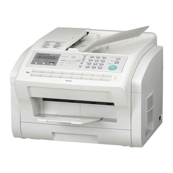
UF-5500 / 4500 7 Location of Controls and Components 7.1. Overview (1) ADF (Automatic Document Feeder) cover (2) Document guides (3) Document tray (4) Control panel (5) Power switch (6) Recording paper tray (7) Recording paper cassette... -
Page 75: Control Panel
(12) (14) (16) (11) (13) (15) (18) (17) The pictured model is UF-5500. The picture shows the position of the UF-4500 Resolution button. (1) Contrast (2) Status (3) Active (4) Resolution (UF-5500 only) * (4) None (UF-4500 only) (5) Scan (UF-5500 only) -
Page 76: Control Panel - For Only Canada (Ac)
(14) (16) (11) (13) (15) (18) (17) * Le modèle UF-5500 est illustré. * L'illustration montre l'emplacement de la touche Résolution sur le modèle UF-4500. (1) Contrast (2) Status (3) Active (4) Resolution (UF-5500 only) * (4) None (UF-4500 only) -
Page 77: Installation Instructions
UF-5500 / 4500 8 Installation Instructions 8.1. Installation 8.1.1. Installation Space The space required to install the unit is shown below. The dimensions given are necessary for the unit to operate efficiently. 10mm 420mm Note: • Avoid excessive heat or humidity. -
Page 78: Document Trsay And Recording Paper Tray
UF-5500 / 4500 8.1.2. DOCUMENT TRSAY AND RECORDING PAPER TRAY Insert the document tray and recording paper tray until it clicks into Document Tray place. Recording Paper Tray Note: • Do not place the unit in an area where the output tray may be easily bumped into. -
Page 79: Recording Paper
UF-5500 / 4500 8.1.3. RECORDING PAPER 8.1.3.1. Using the paper input tray The paper input tray unit can hold: — Up to 250 sheets of 75 g/m (20 lb) paper. • Letter, A4 or Legal-size paper can be used. • Letter, A4 size paper can be used. (UF-4500 only) •... - Page 80 UF-5500 / 4500 Insert the Paper Cassette into the machine, lifting the front part of the cassette. Then push it completely into the machine. Caution for the paper input tray • Do not drop the Paper Cassette. • Hold the Paper Cassette with both hands when removing or install- ing.
-
Page 81: Documents The Unit Can Send
UF-5500 / 4500 8.1.4. Documents the Unit Can Send 8.1.4.1. Using the auto document feeder Note: • Be sure the document(s) is free of staples, paper clips and is not torn, greasy or covered by foreign objects. • Place the document(s) FACE UP on the Automatic Document Feeder (ADF) until the leading edge inserted in the machine stops. - Page 82 UF-5500 / 4500 • The document limitation to send multiple pages is as follows. - Document Size : A4 or Letter size - Document Thickness : 0.0024" to 0.0039" *Please note that although the size meets the specifications, you might not be able to set 30 pages with some types of paper.
-
Page 83: Toner Cartridge And The Drum Cartridge
UF-5500 / 4500 8.1.5. Toner Cartridge and the Drum Cartridge The supplied toner cartridge is a starter toner cartridge. (Prints about 500 pages.) Shake vertically more than 5 times. Remove the protective seal. Note: Pull on the seal slowly and straight out. - Page 84 UF-5500 / 4500 Caution: Watch fingers Set the Toner and Drum Cartridge into the machine. Verify that the arrow marks match. Close the Printer Cover. Printer Cover...
- Page 85 • To check the drum life and quality, please print the printer test list (Refer to (ITU-T No.1 Test Chart (P.248)). If printing quality is still poor or “REPLACE DRUM” appears on the display, replace the toner cartridge and drum cartridge. • To ensure that the unit operates properly, we recommend the use of Panasonic toner and drum cartridges. (Refer to Optional Accessories (P.20)).
-
Page 86: When Connecting Using A Usb Port (Uf-5500 Only)
When Connecting using a USB Port (UF-5500 only) 1.Start Windows and make sure no other applications are running. • You must be logged in as an administrator in order to install the Panasonic Document Management System. 2.Insert the supplied CD-ROM into your CD-ROM drive. -
Page 87: When Connecting Using A Network Port (Uf-5500 Only)
When Connecting using a Network Port (UF-5500 only) 1.Start Windows and make sure no other applications are running. • You must be logged in as an administrator in order to install the Panasonic Document Management System. 2.Insert the supplied CD-ROM into your CD-ROM drive. -
Page 88: Connections
Do not modify the AC outlet. Power Cord (Included) USB Cable (Optional) (USB 2.0): UF-5500 Only For connecting a USB Cable when using your machine as printer and/or scanner. LAN Cable (Optional) : UF-5500 Only For connecting a LAN Cable when using your machine as printer, scanner and/or PC Fax. -
Page 89: User Mode
UF-5500 / 4500 9 User Mode 9.1. Fax Parameter Table Setting Parameter Setting Comments Number CONTRAST NORMAL Setting the home position of the CONTRAST key. LIGHTER DARKER RESOLUTION STANDARD Setting the home position for the RESOLUTION. FINE S-FINE HALFTONE MEMORY (HOME) Setting the home position for memory transmission mode. - Page 90 Selecting whether or not the machine accepts remote reception command. VALID REMOTE DIAG. INVALID Selecting whether or not the machine accepts to update the firmware or Remote Diag- nostics from the remote station. Please ask your Panasonic Authorized Dealer for VALID details. DIAG. PASSWORD (----) Setting the password for Remote Diagnostic Mode.
- Page 91 UF-5500 / 4500 Setting Parameter Setting Comments Number CONFIRMS STNS INVALID Set whether to confirm the destinations. When set to Valid the document cannot be sent unless the destination is confirmed. VALID This function also operates when the addresses are specified with Group Dialing or Pro- gram Dialing function.
-
Page 92: Service Mode
UF-5500 / 4500 10 Service Mode 10.1. Service Modes (For Facsimile) 10.1.1. Service Mode Table The following service modes are provided to assist you in setting operational functions of the unit and determining the condition of the unit. Caution: The factory default parameters are preset (destination dependent) for optimum performance and in compliance with the local telecommunication regulations/standards, and do not need to be changed. -
Page 93: Service Mode 1 (Function Parameter Setting)
10.1.2. Service Mode 1 (Function Parameter Setting) Use the following procedure to change the function parameters. Service Mode 1 LCD Display Step Operation or Unit Condition (The pictured model is UF-5500.) MMM-dd 15:00 Standby SET MODE (1-8) Press “FUNCTION” and then “7”. - Page 94 UF-5500 / 4500 Function Parameter Table Parameter Selections Function MON/TEL DIAL 1 = Monitor Selects whether the machine starts to TX automatically during 2 = TEL/DIAL On-Hook dialing. Monitor : Start to TX after pressing START TEL/DIAL : Start to TX automatically...
- Page 95 UF-5500 / 4500 Function Parameter Table Parameter Selections Function TX START 1 = 2400 bps Selects the transmission modem start speed, 14400/12000/ 2 = 4800 bps TC9600/TC7200/9600/7200/4800/2400 bps. 3 = 7200 bps Note: 4 = 9600 bps This parameter is applicable only when communicating with 5 = TC7200 bps regular G3 machines.
- Page 96 UF-5500 / 4500 Function Parameter Table Parameter Selections Function Not Used PROTOCOL 1 = Off (not displayed) Selects whether to display the modem speed during DISPLAY 2 = On (displayed) communication. Press “V” or “/\ “ to display. Not Used...
- Page 97 UF-5500 / 4500 Function Parameter Table Parameter Selections Function SILENT 01 = 1 sec. Select ring detection integration time (TAM I/F). INTEGRATION TIME 10 = 10 sec. RING COUNT 01 = 1 sec. Select ring detection count 1 to 99 times in one step intervals on (TAM) TAM I/F mode.
- Page 98 UF-5500 / 4500 Function Parameter Table Parameter Selections Function Not Used Service mode ID ******** The password of the service mode is set. Note 1: Function Parameter No. 070 (Line Error)-Transmit condition of RTP/PIP or RTN/PIN Setting Signal 1:128 2:256...
-
Page 99: Service Mode 3 (Printout Of Lists, Reports And Test Results)
10.1.3.1. Function Parameter List A list of all Function Parameters can be printed by the following procedure. Service Mode 3 - Function Parameter List LCD Display Step Operation or Unit Condition (The pictured model is UF-5500.) MMM-dd 15:00 Standby SET MODE (1-8) Press “FUNCTION”... - Page 100 UF-5500 / 4500 Function Parameter List (Sample) *************** -FUNCTION PARAMETER- ************** DATE MMM-dd-yyyy ***** TIME 12:07 *** P.01 000 MON/TEL DIAL : [Monitor] Monitor 050 RING DET MODE : [Normal] Normal 001 ALARM STATUS : [Timer] Timer 051 ---------- 002 STOP COMM.JRNL...
- Page 101 - UF-xxxx - ******************************** - xxxxxxx - ******* - 12345678901234567890 -********* Explanation of Contents: (1) Only for UF-5500 Note: 1. [ ] - Factory Default 2. The contents of the Function Parameter List may vary depending on the destination’s regulations.
- Page 102 A test pattern prints out for checking the page memory and the printer mechanism using the following procedure. Service Mode 3 - Page Memory Test LCD Display Step Operation or Unit Condition (The pictured model is UF-5500.) MMM-dd 15:00 Standby SET MODE (1-8) Press “FUNCTION”...
- Page 103 All printer errors are logged on the Printer Report which can be printed by the following procedure. Service Mode 3 - Printer Report LCD Display Step Operation or Unit Condition (The pictured model is UF-5500.) MMM-dd 15:00 Standby SET MODE (1-8) Press “FUNCTION”...
- Page 104 UF-5500 / 4500 Printer Error Code Table Info. Description of Problems Cause Code Timing Sensor did not turn ON within a certain period of 1. Recording paper jammed when feeding from the 1st time. cassette. 2. The 1st cassette is not installed.
- Page 105 Service Mode 3 - All Document Files LCD Display Step Operation or Unit Condition (The pictured model is UF-5500.) Standby Press “FUNCTION” and then “7”. Press “MONITOR” four times, then press “*”. Enter the key operator password (The factory default ID is 00000000.) and press "Set".
- Page 106 Service Mode 3 - Protocol Trace LCD Display Step Operation or Unit Condition (The pictured model is UF-5500.) Standby Press “FUNCTION” and then “7”. Press “MONITOR” four times, then press “*”. Enter the key operator password (The factory default ID is 00000000.) and press "Set".
- Page 107 Service Mode 3 - Toner Cartridge Order Form LCD Display Step Operation or Unit Condition (The pictured model is UF-5500.) Standby Press “FUNCTION” and then “7”. Press “MONITOR” four times, then press “*”. Enter the key operator password (The factory default ID is 00000000.) and press "Set".
- Page 108 Up to 25 digits (3) Order Tel # Up to 36 digits (4) Order Fax # Up to 36 digits (5) Customer ID Up to 16 characters (User Identification Code) (6) Toner Cartridge # UG-5591 (For USA / Canada) for UF-5500/UF-4500...
- Page 109 Up to 25 digits (3) Order Tel # Up to 36 digits (4) Order Fax # Up to 36 digits (5) Customer ID Up to 16 characters (User Identification Code) (6) Drum Cartridge # UG-5590 (For USA / Canada) for UF-5500/UF-4500...
-
Page 110: Service Mode 4 (Modem Test)
Service Mode 4 - Binary Signal LCD Display Step Operation or Unit Condition (The pictured model is UF-5500.) Standby Press “FUNCTION” and then “7”. Press “MONITOR” four times, then press “*”. Enter the key operator password (The factory default ID is 00000000.) and press "Set". - Page 111 Service Mode 4 - Tonal Signal LCD Display Step Operation or Unit Condition (The pictured model is UF-5500.) Standby Press “FUNCTION” and then “7”. Press “MONITOR” four times, then press “*”. Enter the key operator password (The factory default ID is 00000000.) and press "Set".
- Page 112 Service Mode 4 - DTMF Signal LCD Display Step Operation or Unit Condition (The pictured model is UF-5500.) Standby Press “FUNCTION” and then “7”. Press “MONITOR” four times, then press “*”. Enter the key operator password (The factory default ID is 00000000.) and press "Set".
- Page 113 Service Mode 4 - Binary Signal LCD Display Step Operation or Unit Condition (The pictured model is UF-5500.) Standby Press “FUNCTION” and then “7”. Press “MONITOR” four times, then press “*”. Enter the key operator password (The factory default ID is 00000000.) and press "Set".
-
Page 114: Service Mode 5 (Diagnostic)
Service Mode 5 LCD Display Step Operation or Unit Condition (The pictured model is UF-5500.) Standby Press “FUNCTION” and then “7”. Press “MONITOR” four times, then press “*”. Enter the key operator password (The factory default ID is 00000000.) and press "Set". -
Page 115: Service Mode 6 (Ram Initialization)
Service Mode 6 LCD Display Step Operation or Unit Condition (The pictured model is UF-5500.) Standby Press “FUNCTION” and then “7”. Press “MONITOR” four times, then press “*”. Enter the key operator password (The factory default ID is 00000000.) and press "Set". -
Page 116: Service Mode 7 (Lbp Service Mode)
Service Mode 7 LCD Display Step Operation or Unit Condition (The pictured model is UF-5500.) Standby Press “FUNCTION” and then “7”. Press “MONITOR” four times, then press “*”. Enter the key operator password (The factory default ID is 00000000.) and press "Set". -
Page 117: Service Mode 8 (Check & Call)
UF-5500 / 4500 10.1.8. Service Mode 8 (Check & Call) 10.1.8.1. Overview This feature enables the Authorized Servicing Dealers to manage and improve the Fax machine maintenance to their customers by alerting them of equipment problems. It also can be used as a Supply Sales Tool by alerting the Dealer that the unit is running Low on Toner. -
Page 118: Setting Operation
UF-5500 / 4500 10.1.8.3. Setting Operation CHECK & CALL PRESS SET SET or START SET or START CHECK & CALL SVC. ALERT FAX # CLEAR CLEAR SVC. ALERT FAX # SET or START Enter a destination fax number for the Service Alert Report. - Page 119 UF-5500 / 4500 Note: 1. Service Alert Report To enable the automatic transmission of Service Alert Report, enter the destination fax telephone number in the “SERVICE ALERT (FAX #)” field. When a printer error occurs, the Service Alert Report is transmitted to the designated number automatically.
-
Page 120: Service Alert Report Format
UF-5500 / 4500 10.1.8.4. SERVICE ALERT REPORT FORMAT *************************************************** DATE MMM-dd-yyyy ***** TIME 12:14 ******** **************************** > SERVICE ALERT REPORT < **************************** (2) (3) LAST PRINT ERROR : mm-dd-yy 12:10 No.999-00 CUSTOMER ID ABC COMPANY (4) FAX ROM VERSION TRANSMIT COUNTER : 999999 (6) -
Page 121: Maintenance Alert Report Format
UF-5500 / 4500 10.1.8.5. MAINTENANCE ALERT REPORT FORMAT *************************************************** DATE MMM-dd-yyyy ***** TIME 12:14 ******** **************************** > MAINTENANCE ALERT REPORT < **************************** LAST PRINT ERROR : MACHINE IS RUNNING OUT OF TONER (1) CUSTOMER ID : ABC COMPANY (2) FAX ROM VERSION... -
Page 122: Service Mode 9 (System Maintenance)
Service Mode 9 LCD Display Step Operation or Unit Condition (The pictured model is UF-5500.) Standby Press “FUNCTION” and then “7”. Press “MONITOR” four times, then press “*”. Enter the key operator password (The factory default ID is 00000000.) and press "Set". - Page 123 UF-5500 / 4500 10.1.9.2. Send Received File This function is the relief mode which makes it possible to retrieve memory received documents during a fatal printer error by trans- ferring the documents to another fax machine. MMM-dd 15:00 FUNC MON X 4 SERVICE MODE ENTER NO.
-
Page 124: Troubleshooting Guide
UF-5500 / 4500 11 Troubleshooting Guide 11.1. Starting Troubleshooting 11.1.1. Outline Troubleshooting is for recovering quality and reliability by determining the broken component and replacing, adjusting or cleaning it as required. First, determine the problem then decide the troubleshooting method. If you have difficulty finding the broken part, determine which board is broken. -
Page 125: Improper Lcd Display
UF-5500 / 4500 11.1.2. Improper LCD Display START Check connectors: CN511 (MAIN PCB) and CN2 (OPERATION PCB). When pressing any key, do you hear the 'Pi-' sound from the Speaker? Does CN511, pin 6 and pin 7 on the MAIN PCB measure +5VDC? Replace the OPERATION PCB. -
Page 126: Troubleshooting Details
UF-5500 / 4500 11.2. Troubleshooting Details 11.2.1. Initialization There are two types of initialization, one is the short initialization (about 3 seconds) and the other is the long initialization (about 10 seconds). The short initialization makes the unit enter the standby mode. The long initialization makes the unit enter the standby mode after cleaning or detecting the rest of toner. -
Page 127: Simplified Troubleshooting Guide
UF-5500 / 4500 11.2.2. Simplified Troubleshooting Guide 11.2.2.1. Printing Symptom Cause Countermeasure Ghost Image (P.136) Failed drum cartridge Replace drum cartridge Failed transfer unit Check the transfer roller and spring Failed the high-voltage terminal Check the high-voltage terminal Failed the high voltage power supply board Go to High Voltage Section (P.181) - Page 128 UF-5500 / 4500 11.2.2.2. Recording Paper Feed Symptom Cause Countermeasure Multiple Feed (P.143) Dirty or failed the pickup roller Clean or replace the pickup roller Dirty or failed the pickup rubber Clean or replace the separation rubber The Recording Paper is...
- Page 129 UF-5500 / 4500 11.2.2.3. Copy and FAX Symptom Cause Countermeasure NO DOCUMENT FEED (No Failed the document sensor lever Replace the document sensor lever Document Feed, Docu- Failed the document sensor Go to Sensor Section (P.171) ment Jam and Multiple Doc-...
-
Page 130: Safety Error Information Troubleshooting Guide
UF-5500 / 4500 11.2.3. Safety Error Information Troubleshooting Guide INFO CODE=054 ----- Polygon doesn’t rotate..Refer to LSU (Laser Scanning Unit) Section (P.51). • First, listen to the sound. If rotation sound isn't heard, check 24V line, POLON signal and POLCLK signal. If even a little of sound is heard, check XREADY signal. - Page 131 UF-5500 / 4500 11.2.3.2. INFO CODE=054 "INFO CODE=054" means that the synchronous signal out of the LSU cannot be detected. The synchronous signal out of the LSU is detected by IC 300-G23pin (NHSYNC). After the LCD indicates "INFO CODE=054 ", turn the power OFF/ON, then confirm the waveform when the unit starts initial operation.
- Page 132 UF-5500 / 4500 11.2.3.3. INFO CODE=021 "INFO CODE=021" means that the temperature of the fuser does not rise up to or exceed a constant temperature. The temperature is monitored with the thermistor inside the fuser and detected with the voltage input into IC 300-D19.
- Page 133 UF-5500 / 4500 11.2.3.4. INFO CODE=021 "INFO CODE=021" means that the FAN does not run or the running of the FAN cannot be detected normally. The running of the FAN is detected by IC300-AC20 and W24pin. After repairing, copy. If “INFO CODE=021“ is displayed, check again.
- Page 134 UF-5500 / 4500 11.2.3.5. INFO CODE=051 “INFO CODE=051” means that Engine DC motor’s rotation detection signal (LD) does not become Low. After the LCD indicates "INFO CODE=051", turn the power OFF/ON. INFO CODE=051 Does the DC Check the solder Is 24V output from...
- Page 135 UF-5500 / 4500 11.2.3.6. INFO CODE=090 “INFO CODE=090” indicates that abnormal charge voltage is output from the high voltage unit. INFO CODE=090 appears when the charge voltage turns into abnormal voltage caused by charge wire breaking, short circuit, defect, and contact failure between Drum Cartridge and main frame through charge and GRID terminals.
-
Page 136: Print
UF-5500 / 4500 11.2.4. Print 11.2.4.1. Ghost Image Ghost Distance Drum unit replace. Paper Travel Is the distance of Ghost Is the distance of Ghost about about 75.4 mm (3.0 inches)? ・Is there a scratch on the transfer roller? ・Is the spring of the transfer roller normal? Clean heat roller or ・Are the transfer roller and the blade spring... - Page 137 UF-5500 / 4500 11.2.4.2. Dark or White Vertical Line Clean the cover glass. Paper Travel Drum unit replace ・The scratch and dirt of the heat roller Is the heat roller or the pressurized roller ・The scratch and dirt of the pressurized roller...
- Page 138 UF-5500 / 4500 11.2.4.3. Dark or White Horizontal Line Drum unit replace Paper Travel Is the driving gear normal? Aren't there any flaws or cracks? Is the motor rotating normally? ・It is necessary to describe the information about the lines that cannot be troubleshooted in such as halftone.
- Page 139 UF-5500 / 4500 11.2.4.4. Dirty or Half Darkness Background Drum unit replace. Paper Travel Is paper feed roller dirty? Pick up, Regist, Eject roller Clean paper feed roller. Is the heat roller or the pressure roller dirty? Clean the heat roller or the pressure roller.
- Page 140 UF-5500 / 4500 11.2.4.5. Black Print frame (with frame) Is a sheet of paper printed black in whole? (without frame) Is LSU normal?*1 Paper Travel Drum unit replace Go to LSU Section. *1. Open the Cover. Remove the Drum unit.
-
Page 141: Light Print
UF-5500 / 4500 11.2.4.6. Light Print Clean the cover glass under Drum unit. Paper Travel Drum unit replace Clean the reflecting mirror. Replace the LSU. Is the high-voltage terminal contacting stably? Replace the development high-voltage terminal. HIGH VOLTAGE Go to SECTION. - Page 142 UF-5500 / 4500 11.2.4.7. Black or White Point Drum unit replace Paper Travel Is the exit roller dirty Clean the exit roller. Replace the heat roller Paper or pressure roller. Travel Go to HIGH VOLTAGE SECTION.
-
Page 143: Recording Paper Feed
UF-5500 / 4500 11.2.5. Recording Paper Feed 11.2.5.1. Multiple Feed Is Pick up roller Dirty? Clean or replace the Pick up roller. Check the separation rubber Make sure that the separation rubber is set property. Replace the separation rubber unit. - Page 144 UF-5500 / 4500 11.2.5.3. Skew Is Pick up roller or Pick up rubber Dirty? Clean or replace the Pick up roller. Is Registration roller or Paper feed roller Dirty? Clean or replace the Registration roller. Is paper jammed in its path? Are there any dusts on its path? Remove the paper or dust.
- Page 145 UF-5500 / 4500 11.2.5.4. The Recording Paper Does Not Feed Check the pickup roller rotation. Repair the solenoid. Check the solenoid. Is the pickup roller or Check the registration roller rotation. pickup rubber dirty? Clean the pickup roller. Check pickup sensor Check the driving block.
- Page 146 UF-5500 / 4500 11.2.5.5. The Recording Paper Jam Start Is the pressure roller dirty? Clean or replace the pressure roller. Is the heat roller dirty? Clean or replace the heat roller. Does the separator of heat roller work Replace the separator.
- Page 147 UF-5500 / 4500 Does the print timing sensor work Replace the print timing sensor. properly? CROSS REFERENCE: FAN Motor Section (P.47) When the recording paper jam is occurred, the service mode *630 distinguishes the cause. 0:No Jam 1:Exit Sensor turns ON, though not under the conditions for ON.
-
Page 148: Adf (Auto Document Feeder) Section
UF-5500 / 4500 11.2.5.6. Back Side of The Recording Paper is Dirty Start Is the recording paper path Clean the recording paper path. dirty? Is the Clean the pressure roller. pressure roller dirty? Is the registration roller dirty? Clean the registration roller. - Page 149 UF-5500 / 4500 Check the driving block. Is distortion or broken gear found by visual Replace the gear. Rotation OK? check? Check the connector for the motor and circuit wiring. Go to MOTOR Go to Section. MOTOR SECTION. Replace or fix.
- Page 150 UF-5500 / 4500 11.2.6.2. Skew (ADF) Check whether the document is folded, or if tape or staples are attached. Also check whether a Is the document set ? different size of document is set at the same time and the document guide is set correctly.
- Page 151 UF-5500 / 4500 11.2.6.3. The Sent FAX Data is Skewed Copy the test pattern. (by ADF) Is the test pattern OK? Problem with the other SKEW. Go to FAX machine. CROSS REFERENCE: Skew (ADF) (P.150) 11.2.6.4. The Received FAX Data is Skewed Copy the test pattern.
- Page 152 UF-5500 / 4500 11.2.6.5. The Received or Copied Data is Expanded Copy the test pattern. (by ADF.) Is the test pattern OK? Problem with the other The picture is distorted FAX machine. at ADF. Replace the document feed roller. Replace the separation...
- Page 153 UF-5500 / 4500 11.2.6.6. Black or White Vertical Line is Copied Is the white board dirty? Clean the white board. Isn't the glass of CIS dirty? Clean the glass of CIS. Replace the CIS. 11.2.6.7. An Abnormal Image is Copied Isn't the white board dirty? Clean or replace the white board.
-
Page 154: Communications
UF-5500 / 4500 11.2.7. Communications This section explains general troubleshooting procedures for the 400 series of Information Codes. These errors are primarily caused by poor telephone line quality (loss, noise, echo, etc.). This unit is furnished with Service Mode 1 to assist in troubleshooting line quality problems. -
Page 155: Dialing Problems
UF-5500 / 4500 11.2.7.2. Dialing Problems START Does the unit proceed to Phase B? 1. Set documents on the ADF correctly. 2. Check the telephone line connection. 3. The called party is busy. 4. Refer to Sect. 4.6. Are you using One-Touch,... -
Page 156: Reception Problems
UF-5500 / 4500 11.2.7.4. Reception Problems START Does the machine answer the Ringing signal? 1. Set "RCV = AUTO" 2. Check that all covers are closed firmly. 3. Check the telephone line connection. 4. Check the Ringer Timing, or DRD setting. -
Page 157: Information Codes Table (For Facsimile)
UF-5500 / 4500 11.2.8. Information Codes Table (For Facsimile) Fax Information Codes Code Mode Phase Description of Problem Cause Timing Sensor did not turn ON within a 1. Recording paper jammed when feeding from certain period of time. the 1st cassette. - Page 158 UF-5500 / 4500 Fax Information Codes Code Mode Phase Description of Problem Cause DCN was returned from receiver while Your machine's ID Number is not programmed. transmitter is waiting for CFR or FTT. Possible incompatibility or incorrect Password. DCN was returned from receiver while Receiver working in NON-STD mode only.
- Page 159 UF-5500 / 4500 Fax Information Codes Code Mode Phase Description of Problem Cause Busy Tone is detected after sending NSF Remote station disconnected the line. Signal. Wrong number is dialed. Content of NSF (or DIS) or NSC (or DTC) There is an incompatibility.
- Page 160 UF-5500 / 4500 Fax Information Codes Code Mode Phase Description of Problem Cause Redial count over with no response or busy Telephone line cable is disconnected. tone was not detected. Wrong number is dialed. Note: MAIN PCB is abnormal. U.S.A. and Canadian models will redial only once if a busy tone is not detected.
-
Page 161: Diagnostic Codes (For Facsimile)
UF-5500 / 4500 11.2.9. Diagnostic Codes (For Facsimile) The 16-digit Diagnostic Code (*1) is provided for the service technician to analyze how the communication was performed. The code is recorded on the Journal. Journal Example ***************** -JOURNAL- ************************* DATE MMM-dd-yyyy ***** TIME 15:00 ***** P.01... - Page 162 UF-5500 / 4500 2nd Digit -: Not used/defined Fax Diagnostic Codes Definition Data ID (TSI, CSI, CIG) STOP Button Received Received Received Received Received Received Received Received Received Received Received Received Pressed Received Pressed Received Pressed Received Received Pressed Received...
- Page 163 UF-5500 / 4500 4th Digit -: Not used/defined Fax Diagnostic Codes Definition Data Scanning Rate Resolution 20 ms/line 5 ms/line 10 ms/line 40 ms/line 0 ms/line 20 ms/line Fine 5 ms/line Fine 10 ms/line Fine Fine 40 ms/line Fine Fine...
- Page 164 UF-5500 / 4500 6th Digit -: Not used/defined Fax Diagnostic Codes Definition Data Selective Password Polling XMT/RCV Comm. Comm. 7th Digit -: Not used/defined Fax Diagnostic Codes Definition Data Sub-Address Confidential Turnaround Relayed Comm. Comm. Comm. Polling...
- Page 165 UF-5500 / 4500 8th Digit -: Not used/defined Fax Diagnostic Codes Definition Data Advanced Comm. Cover Sheet XMT Report XMT Check & Call Memory Transfer Report XMT Check & Call Memory Transfer 9th Digit -: Not used/defined Fax Diagnostic Codes...
- Page 166 UF-5500 / 4500 10th Digit -: Not used/defined Fax Diagnostic Codes Definition Data Coding 11th Digit -: Not used/defined Fax Diagnostic Codes Definition Data Symbol Rate (V.34) V.34 2400 sr 2800 sr 3000 sr 3200 sr 3429 sr...
- Page 167 UF-5500 / 4500 12th Digit -: Not used/defined Fax Diagnostic Codes Definition Data Modem Speed Modem Speed (V.34) 2400 bps 4800 bps 2400 bps 7200 bps 4800 bps 9600 bps 7200 bps TC 7200 bps 9600 bps TC 9600 bps...
-
Page 168: Analog Section
UF-5500 / 4500 11.2.10. Analog Section This chapter provides the testing procedures required for the analog parts. A signal route to be tested is determined depending upon purposes. For example, the handset TX route begins at the handset microphone and the signal is output to the telephone line. - Page 169 UF-5500 / 4500 11.2.10.2. DEFECTIVE ITS (Integrated Telephone System) Section 1. No speakerphone transmission / reception Perform a signal test in the ITS or the NCU section and locate a defective point (where the signal disappears) on each route between the microphone and the telephone line (sending), or between the telephone line and the speaker (receiving). Check the components at that point.
- Page 170 UF-5500 / 4500 4. No tone dialing Following the NCU section and ITS section, search for the point where the signal disappears on the route the telephone jack and check the components at that point. (DTMF for TEL LINE: Refer to CHECK SHEET.) CROSS REFERENCE: Check Sheet (P.168)
-
Page 171: Operation Panel Section
UF-5500 / 4500 11.2.11. Operation Panel Section Refer to Operation Board Section (P.62) and LCD Section (P.63). 1. NO KEY OPERATION Do the keys remain pressed Replace the PCB. even when you do nothing? Perform a KEY CHECK. Keys occasionally don't work. - Page 172 UF-5500 / 4500 2. Check the paper exit sensor..“PAPER JAMMED” Check the connection of Check the connection of Check the voltage at pin AD20 of signal line and check the signal line and check the IC300 (Main Board). soldering at R510, R506,...
- Page 173 UF-5500 / 4500 7. Check the top cover sensor ..“TOP COVER OPEN” Check the connection of signal Check the voltage at pin W25 of line and check the soldering at IC300 (Main Board). R516, R517, Q507 (Main Board). The sensor lever pressed: 0V Check the voltage at pin W25 of (The top cover is closed.)
-
Page 174: Motor Section
UF-5500 / 4500 11.2.13. Motor Section 11.2.13.1. Engine Motor Engine MOTOR Does MOTOR rotate to clockwise Check Mechanical Torque. OK? Replace Motor manually ? Check Mechanical parts such as Drum Unit and Fuser. Check Pin1 & 2 of CN1on Motor. -
Page 175: Adf Motor
UF-5500 / 4500 11.2.13.2. ADF Motor ADF MOTOR Check winding resistance of Replace ADF MOTOR ADF MOTOR, Approx. 15Ω ? Are the resistance between 24V and Pin 4,6,7,and 9 of IC700 Replace IC700 more than 1KΩ ? Are excitation voltage output... -
Page 176: Lsu Section
UF-5500 / 4500 11.2.14. LSU Section Is the voltage at pin 1 Check C504, of CN500 about 5V? IC501, D504, C512. Is the voltage at pin 5 Check C501, C503, C505. of CN501 about 24V? Is the POLYGON Does the POLYGON Replace IC300. -
Page 177: Cis Control Section
UF-5500 / 4500 11.2.15. CIS Control Section Are there any stain and/or dust on the glass Clean the stain and/or dust. surface and/or inside the white sheet? Insert document and copy. Is LED lighted? Is the voltage of Is the solder at R548 OK? - Page 178 UF-5500 / 4500 Does CN510 pin1 output a signal? Are the solders at Is the signal input to L363, L364 OK? 3pin and 4pin of IC503? Replace IC300. Do 10,11,12,13pin of IC503 Replace the IC503. output each signal? Are the solders at L365,L366,L367,L368, Solder them again.
-
Page 179: High Voltage Value Check Point
UF-5500 / 4500 11.2.16. High Voltage Value Check Point Measurement Procedure 1. Turn Off the unit, and open the unit cover. 2. Remove the developing unit, if it is equipped. 3. Connect the wire to the terminal to be measured (Fig. 2). The wire should be put out of the unit not to interfere in other termi- nals (Fig. - Page 180 UF-5500 / 4500...
-
Page 181: High Voltage Section
UF-5500 / 4500 11.2.17. High Voltage Section 1. Main Check the HVPS unit failure. Check the voltage of pin8 of HVPS unit. Is +24V power Check the Main Board. output? Check the SW1. Is it normal? Replace the SW1. Check the value of the resistor F1. - Page 182 UF-5500 / 4500 2. CHG, GRID CHG BIAS , GRID Check the connection between Main Is CHG REM signal Board (Pin5 of CN505) and HVPS unit (Pin5) at a low level? (Pin5), and check the Digital unit itself. Check if CHG is no-load Is the abnormal detection or short-circuited.
- Page 183 UF-5500 / 4500 3. TRA (+) TRA (+) BIAS Check the connection between Main Is CHG REM signal Board (Pin5 of CN505) and HVPS unit (Pin5) at a low level? (Pin5), and check the Main Board itself. Is TRA CLK signal Check the Main Board.
- Page 184 UF-5500 / 4500 3. DEV DC DEV BIAS Check the connection between Main Board (Pin5 of CN505) Is CHG REM signal (Pin5) and HVPS unit (Pin5), and at a low level? check the Main Board itself. Check the connection between...
- Page 185 UF-5500 / 4500 TRA (-) TRA (-) BIAS Check the connection between Does the TRA CLK Main Board (Pin3 of CN505) signal (Pin3) turn ON/OFF and HVPS unit (Pin3), and at 5.425kHz? check the Digital unit itself. Does pin14 of IC1...
-
Page 186: Usb Section (Uf-5500 Only)
UF-5500 / 4500 11.2.18. USB Section (UF-5500 only) Troubleshooting 1. Confirmation of the PC settings USB communication failed. All functions that USB communicates are fail Connected to the PC with a USB Is USB cable connected cable with a shield if possible. - Page 187 UF-5500 / 4500 2. Confirmation of the main unit The unit can not communication with PC through USB. Is the voltage of pin1 of Make sure that PC and cable are CN300 about 5V ? connected correctly. Is the frequency of Check R384, C310,C311 and X300.
- Page 188 UF-5500 / 4500 USB (Universal Serial Bus) block Description This is a USB block for data communication with PC. Two signal lines (D+/D-) are differential signals which work in reverse phase. VBUS: CN300 1pin D-: CN300 2pin D+: CN300 3pin...
- Page 189 UF-5500 / 4500 Waveform of normal operation (1) The condition during communication establishment between PC and Main unit at Hi-Speed. Waveform (1)-1 at Hi-Speed Waveform (1)-2 at Hi-Speed V B U S magnification Waveform (1)- 3 at Hi-Speed Waveform (1)-4 at Hi-Speed magnification (2) The condition during communication establishment between PC and Main unit at Full Speed.
-
Page 190: Lan Section (Uf-5500 Only)
UF-5500 / 4500 11.2.19. LAN SECTION (UF-5500 only) LAN Block Diagram Network communication failed. (LAN circuit failure.:In case that LAN settings,Connection cable and peripherals have no problems) Confirm the MAC Address by function parameter 110. Is the voltage of C752 and Is MAC Address Replace the Main Board. - Page 191 UF-5500 / 4500 ① Auto negotiation waveform 1 ② Auto negotiation waveform 2 (A part of the waveform1 is magnified.) about 62.5μ sec about 2msec about 16± 8msec 2. When 100Base-TX-enabled deviced is connected; ① 100Base-TX waveform 1 ② 100Base-TX waveform 2 ( A part of the waveform1 is magnified.)
- Page 192 UF-5500 / 4500 3. When 10Base-T-enabled device is connected. ① 10Base-T waveform 1 [ Link Pulse ] ③ 10Base-T waveform 3 [ during data commnication ] about 16± 8msec ② 10Base-T waveform 2 [ Link Pulse ] ...
- Page 193 UF-5500 / 4500 IC750 (C1CB00002566 : 3.3V Single Power Supply) Pin Description Pin No Signal Name Input/Output(*) Description Ground VDDPLL_1.8 1.8V analog VDD VDDA_3.3 3.3V analog VDD Physical receive or transmit signal (- differential) Physical receive or transmit signal (+ differential)
- Page 194 UF-5500 / 4500 Pin No Signal Name Input/Output(*) Description LED0 / NWAYEN Ipu/O LED Output: Programmable LED0 Output / Config Mode: Latched as Auto-Negotiation Enable (register 0h, bit 12) during power-up / reset. See “Strapping Options“ section for details. The LED0 pin is programmable via register 1Eh bits [15:14], and is defined as follows.
-
Page 195: Main Board Section
UF-5500 / 4500 MAC through the MII. TXD[3..0] has no effect when TXEN is de-asserted. • RMII Tx Mode: The TXD[1:0] bits are synchronous with REF_CLK. For each clock period in which TX_EN is asserted, two bits of data are received by the PHY from the MAC. - Page 196 UF-5500 / 4500 3.3V / 1.2V Troubleshooting Guide (2) 3.3 V / 1.2 V Troubleshooting(2) 3.3V NG 1.2V NG Is Fuse F800 correct? Is the voltage of IC800 pin2 more than 1V? Check Q800, Q801, and IC300 on (1.2V NG) the MAIN Board and replace the parts having the problem.
- Page 197 UF-5500 / 4500 Is the resistance value of 24V after F800 more than 50 ? Check C801, C804, C805, C806, C819, C820, IC800 on the MAIN Board and replace the parts having the problem. Replace the Is the problem MAIN Board.
-
Page 198: Power Supply Board Section
UF-5500 / 4500 11.2.21. Power Supply Board Section 11.2.21.1. Key Components For Troubleshooting Check the following parts first: F1, F2, D1, C5, Q1 and PC1. This comes from our experience with experimental test. For example: power supply and lightning surge voltage test, with standing voltage test, intentional short circuit test, etc. - Page 199 UF-5500 / 4500 11.2.21.2. Troubleshooting Flow Chart Is F1 open? Check the Fuser Unit. Replace F1. Is F2 open? Replace D1. Is D1 short? Is C5 short? Replace C5. Is Q1(D-S, D-G Replace Q1. or S-G) short? Replace F2. Replace D104.
-
Page 200: Information Codes (Info. Codes)
UF-5500 / 4500 11.2.21.3. Broken Parts Repair Details (D1) If D1 is short-circuit, F2 will melt (open). In this case, replace all of the parts (D1, F2). (C5) If overvoltage(Approx. 200V) was supplied for a power supply unit, C5 will be broken. - Page 201 UF-5500 / 4500 Phase Phase A Phase B Phase C Phase D Phase E Message Transmission Facsimile Communication Procedure Facsimile Call Phase A : Call establishment Phase B : Pre-message procedure Phase C : Message transmission Phase D : Post-message procedure...
-
Page 202: Information Codes
UF-5500 / 4500 11.3.1. Information Codes: 400, 420 START START Enable the monitor Is reception from a speaker. (Refer to Sect. reference unit 5.1 Parameter No. 008) successful? Check the line connection from the wall jack to the "Line" on the MAIN PCB. -
Page 203: Information Codes: 401, 402
UF-5500 / 4500 11.3.2. Information Codes: 401, 402, 422 402, 422 START Is Communication with the reference unit successful? Replace the MAIN PCB. Check the remote unit in question. (Remote unit is defective) START Is the ID Number programmed into your machine? Program the ID Number. -
Page 204: Information Codes: 404, 405
UF-5500 / 4500 11.3.3. Information Codes: 404, 405, 407 START Is communication with reference unit successful? Replace the MAIN PCB. Change Function Parameter #010: Reduce Tx Attenuation Level Does the problem still occur? Does the problem still occur? Check the telephone line condition. -
Page 205: Information Code
UF-5500 / 4500 11.3.4. Information Code: 416 START Is communication with the reference unit successful? Replace the MAIN PCB. Change Function Parameter #011: Reduce Rx Sensitivity Level Does the problem still occur? Does the problem still occur? Check the telephone line condition. -
Page 206: Information Codes: 408, 409, 417, 418
UF-5500 / 4500 11.3.5. Information Codes: 408, 409, 417, 418, 490 START Is communication with the reference unit successful? Replace the MAIN PCB. Transmitting Is the unit transmitting or receiving? Does the problem still occur? Receiving Change Function Change Function... -
Page 207: Information Code
UF-5500 / 4500 11.3.6. Information Code: 434 START Is communication with the reference unit successful? Replace the MAIN PCB. Does the trouble occur regardless of the remote unit? Can the transmitter in Check the remote unit in question transmit to the question. -
Page 208: Information Codes: 459, 494
UF-5500 / 4500 11.3.7. Information Codes: 459, 494, 495 START Check the line connection between the telephone jack on the wall and the MAIN PCB. Is communication with the reference unit successful? Replace the MAIN PCB. Does the problem still occur? Check the telephone line condition. -
Page 209: Information Codes: 001, 007 (Recording Paper Jam)
UF-5500 / 4500 11.3.8. Information Codes: 001, 007 (Recording Paper Jam) START Is the recording paper size and thickness within specification? Replace with correct paper. Is the recording paper loaded in the Paper Tray properly? Load the paper correctly. Is the paper tray functional? Replace the paper tray. -
Page 210: Information Codes: 030, 031 (Document Jam)
UF-5500 / 4500 11.3.9. Information Codes: 030, 031 (Document Jam) START Is the document path blocked? Remove the blockage. Does the ADF Motor rotate? 1. Replace the ADF Motor. 2. Replace the MAIN PCB. Does the document feed into the unit? Check all gears and rollers. -
Page 211: Information Codes: 403, 411, 414, 415 (Polling Operator Trouble)
UF-5500 / 4500 CROSS REFERENCE: Communications (P.154) 11.3.11. Information Codes: 403, 411, 414, 415 (Polling Operator Trouble) 403,411,414 START START Inform the remote side Review the polling operation (receiving side) that their referring to the Operating machine does not have Instructions. -
Page 212: Clearing A Document Jam
UF-5500 / 4500 11.4. Clearing a Document Jam If a document becomes jammed in the machine, the display will show the Information Code 030 or 031. Open the ADF Door (1). ADF Cover Remove the jammed document (2). To clear the jam, Info. Code 030... -
Page 213: Clearing A Recording Paper Jam
UF-5500 / 4500 11.5. Clearing a Recording Paper Jam If the recording paper becomes jammed in the machine, the display will show an Information Code 001 or 007. To clear the jam, Info. Code 001 Slide out the Paper Cassette (1). -
Page 214: When The Recording Paper Is Not Fed Into The Unit Properly
UF-5500 / 4500 11.5.1. When the recording paper is not fed into the unit properly The display will show the following. Pull the paper input tray until it clicks into place, then pull it com- pletely out, lifting the front part of the tray. Remove the recording paper and straighten. -
Page 215: Disassembly And Assembly Instructions
UF-5500 / 4500 12 Disassembly and Assembly Instructions Note: Remove the Document Cover, the Paper Input tray and the drum and toner cartridge before reassembling. -
Page 216: Adf Section
UF-5500 / 4500 12.1. ADF Section Remove the Left Cover Remove the ADF unit and Top cover section Remove ADF Top Cover Remove the Doc Conveyer unit Remove Top Cover Section Operation Panel Section... -
Page 217: Remove Adf Section(1)
UF-5500 / 4500 12.2. Remove ADF Section(1) (1) Remove the Left Side Cover. (See the No. C1) Connectors Plot (2) Pull the 4 connectors out. (Fig-01) (3) Remove the screw (F) to release 2 leads. 4 connectors (Fig-02) 2 earth leads... -
Page 218: Remove Pickup-Roller-Cover Unit
UF-5500 / 4500 12.3. Remove Pickup-Roller-Cover Unit Pickup-roller-cover (1) Lift Pickup-roller-cover up until it touches the hook. (2) Lift the Doc-Conveyer Unit up. Doc-Conveyer Unit (3) Twist both left and right levers into inside to release from the hooks. Pickup-roller-cover... - Page 219 UF-5500 / 4500 ADF-Cabinet-Left-Cover ADF-Cabinet-Left-Cover (5) Remove the 3 screws (A). (6) Remove the 2 screws (A). Pickup-roller-cover Unit (7) Remove Pickup-roller-cover Unit lifting up. Pickup-roller-cover Unit...
-
Page 220: Remove Doc-Conveyer Unit
UF-5500 / 4500 12.4. Remove Doc-Conveyer Unit (1) Rotate the Doc-Conveyer unit in the way of the arrow until it is vertical. (2) Remove the Doc-Conveyer lifting straight upward. -
Page 221: Remove Adf Section(2)
UF-5500 / 4500 12.5. Remove ADF Section(2) Stopper Arm Left Cover (1) Remove the 3 screws (A). (2) Release from the Hooks(B). (3) Remove Left Cover. Left Cover Right Cover (4) Remove the 3 screws (A). (5) Release from the Hooks(B). -
Page 222: Operation Panel Unit
UF-5500 / 4500 12.6. Operation Panel Unit (1) Remove the 4 screws (A). (2) Release A hooks to pick the PCB up. (3) Release B hooks to remove the LCD. -
Page 223: Remove Fuser Unit
UF-5500 / 4500 12.7. Remove Fuser Unit (A)-a Fuser Cover and Fuser Unit (1) Remove the bottom plate. (2) Remove the 2 leads for high voltage and 1 connector for the sensor. (Fig-01) (3) Remove the 3 screws (A)-a. (4) Remove the Fuser Cover. -
Page 224: Bottom Section
UF-5500 / 4500 12.8. Bottom Section Remove the Cassette Guide Remove the Bottom Plate Remove the Heat Roller Earth Board Remove the Pick up Roller Remove the Laser unit Remove the Shutter Remove the Low Voltage Power Board Remove theToner Sensor Board... -
Page 225: Remove Main Board
UF-5500 / 4500 12.10. Remove Main Board Left Cover (1) Remove the 4 screws (A). Lithium (2) Remove the 3 Hooks (B). Battery (3) Remove the Speaker Lead. Main Board Fan Motor (4) Remove the Fan Motor. Main Board (4) Remove the 5 screws (C). -
Page 226: Remove Gear Chassis Section
UF-5500 / 4500 12.11. Remove Gear Chassis Section (1) Remove the 4 screws (F)-a. (2) Remove the Motor unit. (3) Remove the 2 screws (F)-c. (4) Remove the 3 screws (J)-a. (5) Remove the Cover Plate. (6) Remove the 2 screws (F)-d. -
Page 227: Remove Right Cover
UF-5500 / 4500 12.12. Remove Right Cover (1) Remove the 4 screws (A). (2) Push the 2 Hooks (B). (3) Remove the AC Inlet. (4) Remove the AC Switch. (5) Remove the Fan Motor. Fan Motor Right Cover AC Switch AC Inlet 12.13. -
Page 228: Remove Bottom Plate
UF-5500 / 4500 12.14. Remove Bottom Plate (1) Remove the 6 screws (A). (2) Remove the 4 screws (B). (3) Remove the Bottom Plate. 12.15. Remove Laser Unit (A)-a (A)-b Pick Sensor Board Laser Unit & Shutter (1) Remove the 3 screws (A)-a. -
Page 229: Remove Pickup Roller
UF-5500 / 4500 12.16. Remove Pickup Roller (A)-a (A)-a Pickup-Roller-Holder (1) Remove the 2 screws (A)-a. Pickup-Roller-Holder (A)-b (2) Remove the Pickup-Roller-Holder. (A)-b Pickup-Roller Unit (1) Remove the 3 screws (A)-b. Pickup-Roller Unit (2) Remove the Pickup-Roller Unit. Paper Guide Unit (1) Open the Paper Guide Unit. -
Page 230: Remove Low Voltage Power Board
UF-5500 / 4500 12.17. Remove Low Voltage Power Board (A)-a Low Voltage Power Board Unit Low Voltage (1) Remove the 4 screws (A)-a. Power Board Unit (2) Remove the screw (A)-b. (3) Remove the each connector. (4) Remove the Low Voltage Power Board Unit. -
Page 231: Remove High Voltage Power Board
UF-5500 / 4500 12.19. Remove High Voltage Power Board (A)-a (1) Remove the 6 screws (A)-a. (2) Remove the all connectors on the High Voltage Power Board. (3) Remove the High Voltage Power Board. (4) Remove the 2 screws (A)-b. -
Page 232: Installation Position Of The Lead
UF-5500 / 4500 12.20. Installation Position of The Lead 12.20.1. Left Side Section(1) Installation detail of FAN Install the FAN in this direction.(label side) UL tape Be passed outside of the boss. Dressing of LEAD on MAIN BOARD For detail,please see next page. -
Page 233: Left Side Section(2)
UF-5500 / 4500 12.20.2. Left Side Section(2) Detail Dressing of LEAD Cram the core and ADF/SENSOR_LEAD into the opening. Harness must not come out above this line. < N G > IC 4 0 0 IC 3 0 0 Don't touch and pass ADF/SENSOR_LEAD between IC400 and IC300. -
Page 234: Right Side Section
UF-5500 / 4500 12.20.3. Right Side Section Installation detail of FAN Air Flow direction (to Set inside) Install it in this direction.(no label side) UL tape Lead style around AC inlet Set the LEAD/AC EARTH core like this figure. (Please ignore the cavinet color, and harness color.) -
Page 235: Bottom Part Section (1)
UF-5500 / 4500 12.20.4. Bottom Part Section (1) Pass the lead/Thermistor Pass these leads through the groove. between these boss. Enter to Hook completely. Black White UL tape Pass the leads through the hole as shown in this figure. -
Page 236: Bottom Part Section (2)
UF-5500 / 4500 12.20.5. Bottom Part Section (2) LEAD/FUSER Bind for following leads around a boss with a binder. LEAD/AC EARTH HARNESS/AC LEAD/FUSER LEAD/HV Don't insert LEAD/FUSER and HARNESS/AC by mistake. HARNESS/AC Dressing of LEAD/AC EARTH SCREW Terminal of Harness... -
Page 237: Maintenance
UF-5500 / 4500 13 Maintenance 13.1. Maintenance Items and Component Locations 13.1.1. Outline MAINTENANCE AND REPAIRS ARE PERFORMED USING THE FOLLOWING STEPS. 1. Periodic maintenance Inspect the equipment periodically and if necessary, clean any contaminated parts. 2. Check for breakdowns Look for problems and consider how they arose. - Page 238 UF-5500 / 4500 13.1.2.2. Maintenance Cycle (Document & Paper) Item Cleaning Cycle ADF Document Feed Roller (Ref.No.64) 3 months ADF Separation Rubber (Ref. No.45) 3 months ADF Eject Roller (Ref.No.79) 3 months Pickup Roller (Ref No.321) ------------ Separation Roller (Ref. No.351) ------------ Feed Roller (Ref.No.210)
-
Page 239: Printing Operation Principle
UF-5500 / 4500 13.2. Printing Operation Principle 13.2.1. Process Chart and Process BIAS Transfer Roller Transcription Bias -4 to -25µA (-500 ~ -4200V)constant current (depends on the printing ratio) Pressure Roller OPC Drum 108.96mm/sec Grid plate Developing Roller AC 120V Developing Bias DC 170~240V &... -
Page 240: Exposing
UF-5500 / 4500 13.2.3. Exposing When the drum which is charged with the fixed electric charge is irradiated by the laser beam, the plus charge and minus charge are generated at the Charge Generation Transfer Layer. Passing through the Charge Generation Transfer Layer which conducts the minus charge, the plus-charged drum's surface is neutralized to be skipped. -
Page 241: Developing And Transcription
UF-5500 / 4500 13.2.4. Developing and Transcription The developing is the stage that the OPC drum with an invisible image is changed to visible by the toner. The drum cartridge con- sists of mixing paddle, toner supply roller, developing roller, developing blade, charge wire, grid plate and OPC drum. The bias volt- age is added to the developing roller and toner supply roller. -
Page 242: Cleaning Of Transfer Roller
UF-5500 / 4500 13.2.5. Cleaning of Transfer Roller The toner attached to the surface of the OPC drum is transferred to the paper at the transcription stage, but a part of the toner remains. The cleaning is the stage that cleans the remain toner after the transcription stage. The remain toner on the drum and the toner which was attached to the place where the laser beam didn't scan are gathered to the developing roller to be used again. -
Page 243: Fixing
UF-5500 / 4500 13.2.6. Fixing On the process of the transfer, the transferred toner is weakly attached on the paper. Fixing means the process to fix the toner on the paper permanently. The fixing part melts the toner at the high temperature using the halogen heater. The toner is fixed on the paper by the heat and pressure through the fixing part with the image. -
Page 244: How To Replace The Flat Package Ic
UF-5500 / 4500 13.3. How to Replace the Flat Package IC Even if you do not have the special tools (for example, a spot heater) to remove the Flat IC, with some solder (large amount), a soldering iron and a cutter knife, you can easily remove the ICs that have more than 100 pins. -
Page 245: Flat Package Ic Installation Procedure
UF-5500 / 4500 13.3.3. Flat Package IC Installation Procedure 1. Temporarily fix the FLAT PACKAGE IC, soldering the two marked pins. *Check the accuracy of the IC setting with the corresponding soldering foil. 2. Apply flux to all pins of the FLAT PACKAGE IC. -
Page 246: Main Board Section
UF-5500 / 4500 13.4. Main Board Section When the unit fails to boot up the system, take the troubleshooting procedures very carefully. It may have a serious problem. The symptom: No response when the power is turned on. (No LCD display, and keys are not accepted.) The first step is to check the power source. -
Page 247: Ng Example
UF-5500 / 4500 13.4.1. NG Example Short circuit from the adjacent signal wires. Check for a short circuit in the RA and IC leads and the signal wire at the through hole. Solder waste Solder ball Through hole Short between the signal line and GND. -
Page 248: Test Chart
UF-5500 / 4500 13.5. Test Chart 13.5.1. ITU-T No.1 Test Chart... -
Page 249: Itu-T No.2 Test Chart
UF-5500 / 4500 13.5.2. ITU-T No.2 Test Chart... -
Page 250: Updating The Firmware
7. After the update is completed, the machine reboots itself and returns to standby. Confirm parameters according to the printed lists in Step 1. if the settings are different. 13.6.2. Updating through a LAN Port (UF-5500 only) The firmware code can be easily updated when the main unit is connected to a LAN. -
Page 251: Firmware Version
UF-5500 / 4500 13.6.3 Firmware Version HOST UF-5500 A A V1xxxx AU UF-4500 Destination Code (Fax) AU : USA / Canada Firmware Version (V1.xxxx) Language Code A : US English, C-French & Spanish B : US English, Spanish & Portuguese b : English, French &... -
Page 252: Schematic Diagram
UF-5500 / 4500 14 Schematic Diagram 14.1. For Schematic Diagram Note: 1. DC voltage measurements are taken with an oscilloscope or a tester with a ground. 2. The schematic diagrams and circuit board may be modified at any time with the development of new technology. -
Page 253: Main Board (Uf-5500)
FANDET2 3:2F TOPCVR TONEAVSS SCIO18 1 DS 3:5C SCIO19/EXSEN4 PSTART AC11 3:5F TEST SCIO20 RESOLUTION AD11 CLKSEL SCIO21 AC18 NWDTRST SCIO22 3 NC AD18 NRST SCIO23 R304 100 3:3A SCIO24 NHSYNC XSYSRST 5C;2:2E;3:2E UF-5500 SCHEMATIC DIAGRAM (MAIN BOARD No.1) (1/3) - Page 254 32.768KHZ VSS_46 R380 PLL24VDD C25 VSS_47 PLL240VSS B26 K0.22u C304 VSS_48 VSS_49 R381 PLL393VDD AE24 VSS_50 K0.22u PLL393VSS AF25 C305 VSS_51 VSS_52 R382 PLL266VDD2 AF2 VSS_53 PLL266VSS2 AE3 K0.22u C306 VSS_54 VSS_55 VSS_56 UF-5500 SCHEMATIC DIAGRAM (MAIN BOARD No.1) (2/3)
- Page 255 UF-5500 / 4500 +3.3V +3.3V R395 0(1608) +1.2V +24V +5VD R396 0(1608) R397 0(1608) R398 0(1608) UF-5500 SCHEMATIC DIAGRAM (MAIN BOARD No.1) (3/3)
-
Page 256: Main Board (2)
FRMA[21] DQ12 1:3C FRMD[4] NFRWE XSYSRST FRMA[22] 1:2F;1:5C;3:2E DQ11 FRMD[3] VPP/*WP DQ10 FRMA[19] FRMD[2] FRMA[18] FRMA[8] FRMD[1] FRMA[7] FRMA[6] FRMD[0] FRMA[5] FRMA[4] VSS1 FRMA[3] FRMA[2] VCCQ FRMA[1] 1:3A FRMA[0-23] 1:3C NFRCE 1:3C NFROE UF-5500 SCHEMATIC DIAGRAM (MAIN BOARD No.2) (1/2) - Page 257 1:4B RX_CLKI 7 TX+ 1:4B RXDV/CRSDV/CONFIG2 RX_DV 8 XO VDDIO_3.3 C756 +3.3V D10p C757 J15p R754 F6.49k R764 1:4C C770 R765 1:4C J100p MDIO 1:4B RXD[0-3] LAN circuit 25MHz UF-5500 ONLY UF-5500 ONLY UF-5500 SCHEMATIC DIAGRAM (MAIN BOARD No.2) (2/2)
-
Page 258: Main Board (3)
300DPI Q504 1:3D R589 Q501 R520 (15) HVERR 1:3D HVERR 1:3F 1.32ms TOPCVR CN505 R516 Q507 TO HVPS 1.3msec 1.3msec 4500 2.5MHz 1.1msec 5500 copy fax Tx 4.46MHz 5500 PC SCAN 5.208MHz UF-5500 SCHEMATIC DIAGRAM (MAIN BOARD No.3) (1/2) 4.46MHZ... - Page 259 R541 1:6B PICK (10) LEDONG 1.2k 1:6B (11) LEDONR 1:6B +24V (12) LEDONB REGISTER 1:6A (13) CCDSH SOLENOID R574 CN514 Q524 8.2k(2125) 1:3D 1:6A Q523 (14) CCDCLK SNREG 1 REG 1:3F (15) RESOLUTION UF-5500 SCHEMATIC DIAGRAM (MAIN BOARD No.3) (2/2)
-
Page 260: Main Board (4)
R212 22k (17) C205 K0.1u R221 +3.3VA2 R211 NC R259 C250 C204 C214 C219 VREF Q200 1:4A;1C R222 L215 AFERST 1:3E CNGMUTE 180k C220 K1000p Q203 1:1D HSSPMUTE2 MONITOR_RX: TONE FAX-TX,RX : MONITOR_RX: UF-5500 SCHEMATIC DIAGRAM (MAIN BOARD No.4) (1/2) - Page 261 R235 L220 2 SP- K3900p K0.022u 1 SP+ +5VA +3.3V CN200 CN201 R252 1:3D HOOK (15) C226 R230 (16) L223 C227 R231 L221 (17) L224 L222 D200 C230 MONITOR_RX: TONE FAX-TX,RX : MONITOR_RX: UF-5500 SCHEMATIC DIAGRAM (MAIN BOARD No.4) (2/2)
-
Page 262: Main Board (Uf-4500)
UF-5500 / 4500 14.3. Main Board (UF-4500) 14.3.1. Main Board (1) 2:4E IC300 SDMD[0-15] FRMD[0-7] SDMD[0] FRMD0 A14 FRMD[0] 2:2F SDMD0 SDMD[1] FRMD[1] FRMA[0-23] FRMD1 B14 SDMD1 SDMD[2] FRMD2 C14 RA320 FRMD[2] SDMD2 SDMD[3] FRMD3 A15 FRMD[3] SDMD3 SDMD[4] FRMD[4]... - Page 263 UF-5500 / 4500 +3.3V IC300 CCDSH C6 3:5E AFESEL0 CCDSH NCCDRS B6 L361 3:5E AFESEL1 CCDCLK 4:1B L359 15BD471 NCCDCP A5 AA24 4:1C;4:1E L356 15BD471 CCDCLK A6 AFERST AFERST L363 1D;4:1B L358 15BD471 AA25 AFEVSMP B5 3:5D RING RING AFEVSMP...
- Page 264 UF-5500 / 4500 +3.3V +3.3V R395 0(1608) +1.2V +5VD +24V R396 0(1608) R397 0(1608) R398 0(1608) UF-4500 SCHEMATIC DIAGRAM (MAIN BOARD No.1) (3/3)
-
Page 265: Main Board (2)
UF-5500 / 4500 14.3.2. Main Board (2) +3.3V 1:1A SDMD[0-15] SDMD[0] SD[0] SDMD[1] RA400 SD[1] SDMD[2] SD[2] +3.3V SDMD[3] SD[3] SDMD[4] SD[4] SDMD[5] SD[5] RA401 SDMD[6] SD[6] SDMD[7] SD[7] IC400 SDMD[8] SD[8] SDMD[9] RA402 SD[9] SDMD[10] SD[10] SD[0] SD[15] SDMD[11]... - Page 266 UF-5500 / 4500 +24V +24VIN C809 R812 K0.047u F2.2k R802 R801 +3.3V R800 F10k 1% F1k 1% Gate F22k 1% Q804 CL800 IC800 CL801 R819 L800 Q806 470(3216) Q802 +1.2V Q805 CL803 CL804 R820 L801 470(3216) Q807 Q803 R815 R817...
-
Page 267: Main Board (3)
UF-5500 / 4500 14.3.3. Main Board (3) +3.3V +3.3V TO OPE CN500 +5VD CN511 +5VD C504 Z0.1u R562 1:1E THRM THRMSTR0 R563 1:3E KSTART KSTART 1:3F XHSYNC R559 1:3E NHSYNC KTXD KTXD R511 L500 1:3D XVIDEO J180p R560 1:3E NVIDEO... - Page 268 UF-5500 / 4500 Not used. +24V Flat bed circuit IC502 TO FBM 1:1D;6B CRM0 1:1D;6C 24 I01 CN509 NC CRM2 PHA1 1:1D;6C 23 I11 CRM3 PGND 22 VREF 21 CR1 CR_A OUT1A +3.3V 20 PS RNF1 CR_XA 19 GND OUT1B...
-
Page 269: Main Board (4)
UF-5500 / 4500 14.3.4. Main Board (4) FAX-RX R114 F536(3216) C106 R104 50V/1u 1.07k(1/2W) 1:1D;1:4A RING 1:4A +3.3VA1 IC100 IC101 Q102 R111 1:4B;1E 1 QE AFECLK *OFHK MCLK +3.3VA1 DCT2 1:4B 2 *FSYNC 2 DCT R108 ASPCLK IGND *RGDT/FSD/M1 3.65k(1/2W) - Page 270 UF-5500 / 4500 +5VD RLY100 Q100 1:3D EXTRLY MONITOR-RX L111 D103 R135 F100 Q104 L100 L106 Q103 L107 2 C113 250V 0.01u/250V Q106 R116 R129 POS100 12(1W) L101 L110 L105 2.49k(1/2W) CN100 C112 R134 R125 K0.01u 12(1W) R118 R120 100k...
-
Page 271: Operation Board (Uf-5500)
UF-5500 / 4500 14.4. Operation Board (UF-5500) -
Page 272: Operation Board (Uf-4500)
UF-5500 / 4500 14.5. Operation Board (UF-4500) -
Page 273: Sensor Board (Uf-5500)
UF-5500 / 4500 14.6. Sensor Board (UF-5500) PNLPU55AUS-A CIS_RLY PNLPU55AUS-F POUT THRM1 CN64 CN65 CN59 CN61 POUT C66 K1000p THRM1 +3.3V +3.3V Z0.1u VREF VREF FANON FANON FANDET FANDET PICK PICK IC51 PTOP VLED VLED VOUT CN67 CISHOME PTOP CN66... -
Page 274: Sensor Board (Uf-4500)
UF-5500 / 4500 14.7. Sensor Board (UF-4500) PNLPU55AUS-A POUT THRM1 CN64 CN65 POUT THRM1 FANON FANON FANDET FANDET PICK PICK IC51 PTOP VOUT CN67 PTOP CN66 CIS_RLY PNLPU45AUS-K Fuser Varistor PNLPU55AUS-B PNLPU55AUS-E ZNR50 CN79 CN53 THRM1 PS50 +3.3V POUT +3.3V... -
Page 275: High Voltage Power Supply Board
J104 J103 H:Normal L:Abnormal R40 C32 H:OFF PWM Control DEV CLK Freq:5.425KHz 5.6V T61(B61) TRA+/- 60KHz JUMPER 10mm Approx.50V J107 J108 JUMPER 10mm H:OFF PWM Control TRA CLK Freq:5.425KHz 5.6V D71 D72 UF-5500 / UF-4500 HIGH VOLTAGE POWER SUPPLY BOARD... -
Page 276: Low Voltage Power Supply Board
UF-5500 / 4500 14.9. Low Voltage Power Supply Board... -
Page 277: Exploded View And Replacement Parts List
UF-5500 / 4500 15 Exploded View and Replacement Parts List RTL (Retention Time Limited) Notes: 1. The "RTL" marking indicates that its Retention Time is Limited. When production is discontinued, this item will continue to be available only for a specific period of time. This period of time depends on the type of item, and the local laws governing parts and product retention. -
Page 278: Adf Section
UF-5500 / 4500 15.1. ADF Section Safety Ref. No. Part No. Part Name & Description Remarks PNKV1104Z1 COVER PNKV1105Z1 COVER PNKV1103Y1 COVER PNHD1012Z SMALL SCREW, STEEL XTW3+10PFJ7 SCREW... - Page 279 UF-5500 / 4500 ADF Cover Section ADF Conveyer Section ADF Pickup Section Operation Panel Section ADF Lower Cabinet Section...
-
Page 280: Adf Cover Section
UF-5500 / 4500 15.2. ADF Cover Section Safety Ref. No. Part No. Part Name & Description Remarks PFDE1247X LEVER PFDF1095Y SHAFT PFDJ1044Z SPACER PFUS1624Y COIL SPRING PFHG1222Z RUBBER PARTS PNKV1107Z1 COVER PNKV1097W1 COVER PFDR1065Y ROLLER PFDG1413Y GEAR PFDG1416Z GEAR PFDG1417Z... - Page 281 UF-5500 / 4500...
-
Page 282: Adf Conveyer Section
UF-5500 / 4500 15.3. ADF Conveyer Section Safety Ref. No. Part No. Part Name & Description Remarks PNKR1012Z1 GUIDE PNKR1011Z1 GUIDE PNKE1101Z1 GUIDE PFUS1622Z COIL SPRING PFDG1015Y GEAR PFZCFLB851M PARTS KIT NOT USED NOT USED PFDG1297Z GEAR PFDG1177Z GEAR NOT USED... - Page 283 UF-5500 / 4500 PCB9 PCB11...
-
Page 284: Adf Pickup Section
TORSION SPRING PFDR1073Z ROLLER PNKV1106Y1 COVER PFUS1643Z COIL SPRING PFDR1066Z ROLLER PNZCUF5500AU SCANNER GLASS ASS’Y PNWYUF5500AU IMAGE SENSOR ASS’Y (UF-5500 only) PNWYUF4500AU IMAGE SENSOR ASS’Y (UF-4500 only) PNZXUF5500AU SCANNER BASE ASS’Y PNMH1191Y METAL PARTS PNMH1192Y METAL PARTS PNHX1443Z SPACER PNHX1483Z... - Page 285 UF-5500 / 4500 100(The pictured model is UF-5500.) (The pictured model is UF-4500.) 118(The pictured model is UF-5500.)
-
Page 286: Operation Panel Section
PUSH BUTTON,SET KEY (for UF-5500 / 4500-AU) PNBC1286Q2 PUSH BUTTON,SET KEY (for UF-5500 / 4500-AC) PNBC1285Y2 PUSH BUTTON,CURSOR KEY PNBC1295Z2 PUSH BUTTON,MENU KEY PCB2 PNLPU55AUK-A OPERATION BOARD ASS'Y (for UF-5500 only) PCB2 PNLPU45AUK-A OPERATION BOARD ASS'y (for UF-4500 only) XTW3+10PFJ7 SCREW... - Page 287 UF-5500 / 4500 PCB2 (UF-5500 only)
-
Page 288: Adf Lower Cabinet Section
PFUS1269Y COIL SPRING PNHG1095Z RUBBER PARTS NOT USED PNHS1182Y SPACER PNDE1022Y1 PNUS1100X COIL SPRING PCB4 PNLPU55AUK-B ADF SENSOR BOARD ASS'Y PCB8 PNLPU55AUS-F RELAY/CIS BOARD ASS'Y (RTL) (for UF-5500 ONLY) PCB8 PNLPU45AUS-K RELAY/CIS BOARD ASS'Y (RTL) (for UF-4500 ONLY) XTW3+10PFJ7 SCREW... - Page 289 UF-5500 / 4500 PCB4 PCB8...
-
Page 290: Main Cabinet Section
UF-5500 / 4500 15.7. Main Cabinet Section Safety Ref. No. Part No. Part Name & Description Remarks PNQT2154Z INDICATION PLATE-LABEL NOT USED PFSE1054Z ANGLE PNUE1011Y AIR DACT PFJV1013Z METAL PARTS PFDG1420Y GEAR PFDJ1044Z SPACER PNDN1005Z ROLLER PFDJ1086X SPACER PFUS1613Z COIL SPRING... - Page 291 UF-5500 / 4500 Fuser Section...
-
Page 292: Fuser Section
UF-5500 / 4500 15.8. Fuser Section Note: (*1) After the production of this model is discontinued, this fuser unit can not be supplied. Safety Ref. No. Part No. Part Name & Description Remarks PFHR1705Y PNDJ1021Z BUSH PFUS1426Z COIL SPRING PFHR1495Z... - Page 293 UF-5500 / 4500 Heat Roller PCB14...
-
Page 294: Bottom Cabinet Section
UF-5500 / 4500 15.9. Bottom Cabinet Section Safety Ref. No. Part No. Part Name & Description Remarks PNUS1092Y LEAF SPRING PF0M1008Z MIRROR PNHS1196Z FELT PARTS PNJS101006Z CONNECTOR LPA1605K LASER PNJS071028Z CONNECTOR PNJS081057Z CONNECTOR PNJS051021Z CONNECTOR PNQT1998Z LABEL PFUS1592Z TORSION SPRING... - Page 295 UF-5500 / 4500 PCB12 PCB3 PCB13 PCB5 PCB7 PCB6...
-
Page 296: Double Feed Prevention Holder Section
UF-5500 / 4500 15.10. Double Feed Prevention Holder Section Safety Ref. No. Part No. Part Name & Description Remarks PFNPD041065C SPACER PNUS1104Z COIL SPRING PFUS1923Z COIL SPRING PNHR1235Z PLASTIC PARTS PNDF1027Z SHAFT PNDR1020Z ROLLER PFHR1538Z CABINET ACCESSORY PNUS1102Z COIL SPRING... - Page 297 UF-5500 / 4500...
-
Page 298: Side Cabinet Section
LEAD WIRE PNJS021063Z CONNECTOR PNDE1021Z1 LEVER L6FAYYYK0017 DC MOTOR PNHS1285Y FELT PARTS PCB1 PNWP1U5500AU MAIN BOARD ASS'Y (RTL) (UF-5500 only) PCB1 PNWP1U4500AU MAIN BOARD ASS'Y (RTL) (UF-4500 only) PCB10 PNLPU55AUS-H HANDSET RELAY BOARD ASS'Y (RTL) XTW3+10PFJ7 SCREW XTW3+6LFJ7 SCREW XTW3+12PFJ7... - Page 299 UF-5500 / 4500 Motor PCB1 PCB10 Section...
-
Page 300: Motor Section
UF-5500 / 4500 15.12. Motor Section Safety Ref. No. Part No. Part Name & Description Remarks PFNPD052080 SPACER PFDG1544Y GEAR PFDG1548Z GEAR PFDG1543Z GEAR PFDG1549Z GEAR L6CCYYYK0006 DC MOTOR PNHX1255Z PLASTIC PARTS PNMH1067Z METAL PARTS PFMD1111W CHASSIS GEAR MAIN ASS’Y... - Page 301 UF-5500 / 4500...
-
Page 302: Bottom Section
WASHER PFHA1001Z RUBBER PARTS L0AA05A00048 SPEAKER PNJS021060Z CONNECTOR PNKV1076Z2 COVER PNKV1062Z2 COVER (UF-5500 only) PNKV1062Y2 COVER (UF-4500 only) PFQT3054Z INDICATION PLATE-LABEL (UF-5500 only) PQHR945Z BAND PNHS1286Y FELT PARTS PNHX1468Z USB SHEET (UF-4500 only) XTW3+10PFJ7 SCREW XTW3+6LFJ7 SCREW XTW3+W10PFJ SCREW XSB4+6FJ... - Page 303 UF-5500 / 4500 451(UF-5500 only) 454(UF-4500 only)
-
Page 304: Cassette Section
UF-5500 / 4500 15.14. Cassette Section Safety Ref. No. Part No. Part Name & Description Remarks PNQT1012Z INDICATION PLATE-LABEL (for UF-5500/4500-AU) PNQT1012A INDICATION PLATE-LABEL (for UF-5500/4500-AC) PNQT2153Z INDICATION PLATE-LABEL (for UF-5500/4500-AU) PNQT2153C INDICATION PLATE-LABEL (for UF-5500/4500-AC) PFHG1245Z RUBBER PARTS PFUS1814Z... - Page 305 UF-5500 / 4500...
-
Page 306: Actual Size Of Screws And Washer
UF-5500 / 4500 15.15. Actual Size of Screws and Washer Safety Ref. No. Part No. Part Name & Description Remarks XTW3+10PFJ7 TAPPING SCREW, STEEL XYC3+CF6FJ SCREW WITH WASHER, STEEL XTW3+20PFJ TAPPING SCREW, STEEL XTW3+12PFJ7 TAPPING SCREW, STEEL XYC3+FF8FJ SCREW WITH WASHER, STEEL... - Page 307 UF-5500 / 4500 Illustration XTW3+10PFJ7 XTW3+6LFJ7 XTW3+12PFJ7 XTW3+W10PFJ XYC3+FF8FJ XYC3+CF6FJ XTB3+10GFJ XTB3+12JFJ XTW3+20PFJ XSB4+6FJ...
-
Page 308: Accessories And Packing Materials
LEAFLET NOT USED PNKS1011Z2 TRAY PNKS1010Z2 TRAY PNKS1014Z1 TRAY PNJA1022Z POWER CORD PFJA02B002Y CORD PNQW2714Z IIG (Canadian French) (for UF-5500/4500-AC) PNPK31852Y-M PACKING CASE (UF-5500 only) PNPK31853Y-M PACKING CASE (UF-4500 only) PNPN1204Z CUSHION PNPN1205Z CUSHION PFPP1041Z PROTECTION COVER PNPN1188Z CUSHION PNPN1189Z... - Page 309 UF-5500 / 4500 Drum Cartridge Toner Cartridge...
-
Page 310: Optional Legal Paper Cassette
UF-5500 / 4500 15.17. Optional legal paper cassette Safety Ref. No. Part No. Part Name & Description Remarks PFUS1814Z TORSION SPRING PFHG1245Z RUBBER PARTS PNMD1060Z CHASSIS PNUS1103Z COIL SPRING PFDG1015Y GEAR PFHR1491Z LEVER PFUS1608Z COIL SPRING PNHS1174Z FELT PARTS PNKK1057Z1... - Page 311 UF-5500 / 4500...
-
Page 312: Replacement Parts List
Ref. Part No. Part Name & Description Remarks D306 B0ZBZ0000146 DIODE(SI) 15.18.1. Main Board D308 B0BC5R000009 DIODE(SI) D501 B0ACEL000004 DIODE(SI) 15.18.1.1. Main Board (UF-5500 only) D503 B0ACEL000004 DIODE(SI) D504 B0ACEL000004 DIODE(SI) D800 B0JCPD000033 DIODE(SI) Safety Ref. Part No. Part Name & Description Remarks... - Page 313 UF-5500 / 4500 Safety Ref. Part No. Part Name & Description Remarks Safety Ref. Part No. Part Name & Description Remarks C326 ECUE1C103KBQ 0.01 C534 ECUE1A104KBQ 0.1 C327 ECUE1C104ZFQ 0.1 C536 ECUE1A104KBQ 0.1 C328 ECUE1C104ZFQ 0.1 C537 ECUE1A104KBQ 0.1 C329 ECUE1C104ZFQ 0.1...
- Page 314 UF-5500 / 4500 Safety Ref. Part No. Part Name & Description Remarks Safety Ref. Part No. Part Name & Description Remarks C691 ECUE1C104ZFQ 0.1 CN750 K2LC1YYB0040 JACK C692 ECUE1C104ZFQ 0.1 (FUSE) C693 ECUE1C104ZFQ 0.1 F800 K5H302Y00003 FUSE C695 ECUE1C104ZFQ 0.1...
- Page 315 UF-5500 / 4500 Safety Ref. Part No. Part Name & Description Remarks Safety Ref. Part No. Part Name & Description Remarks R103 ERJ2RKF1004 R380 ERJ2GEJ1R0 R104 ERJ12SF1071 1.07k R381 ERJ2GEJ1R0 R105 ERJ2GE0R00 R382 ERJ2GEJ1R0 R106 ERJ6GEYJ515 5.1m R384 ERJ2GEJ101 R107 ERJ6GEYJ515 5.1m...
- Page 316 UF-5500 / 4500 Safety Ref. Part No. Part Name & Description Remarks Safety Ref. Part No. Part Name & Description Remarks R550 ERJ2GEJ122 1.2k R822 ERJ2GEJ473 R552 ERJ2GEJ102 R825 PQ4R18XJ102 R553 ERJ2GEJ820 R826 PQ4R18XJ102 R554 ERJ2GEJ122 1.2k (COMPONENTS PARTS) R555 ERJ2GEJ472X 4.7k...
- Page 317 UF-5500 / 4500 Safety Ref. Part No. Part Name & Description Remarks Safety Ref. Part No. Part Name & Description Remarks Q500 B1ABCF000103 TRANSISTOR(SI) C121 F1LAF100A009 10p Q501 UNR92ANJ0L TRANSISTOR(SI) C125 ECUE1C103KBQ 0.01 Q502 UNR92ANJ0L TRANSISTOR(SI) C200 F2G0J1010014 100 Q503...
- Page 318 UF-5500 / 4500 Safety Ref. Part No. Part Name & Description Remarks Safety Ref. Part No. Part Name & Description Remarks C412 ECUE1C103KBQ 0.01 C651 ECUE1C104ZFQ 0.1 C413 ECUE1C104ZFQ 0.1 C652 ECUE1C104ZFQ 0.1 C414 ECUE1C104ZFQ 0.1 C653 ECUE1C104ZFQ 0.1 C419...
- Page 319 UF-5500 / 4500 Safety Ref. Part No. Part Name & Description Remarks Safety Ref. Part No. Part Name & Description Remarks C820 PQCUV1C105ZF 1 (THERMISOTS) (CONNECTORS AND JACKS) POS100 D4DAY220A022 THERMISTOR CN100 K2LB1YYB0002 JACK/SOCKET (RESISTORS) CN101 K2LB1YYB0002 JACK/SOCKET L200 ERJ3GEY0R00...
- Page 320 UF-5500 / 4500 Safety Ref. Part No. Part Name & Description Remarks Safety Ref. Part No. Part Name & Description Remarks R343 ERJ2GEJ103 R525 ERJ12YJ390 R344 ERJ2GEJ103 R526 ERJ2GEJ103 R345 ERJ2GEJ103 R527 ERJ2GEJ562X 5.6k R346 ERJ2GEJ103 R528 PQ4R10XJ332 3.3k R347...
- Page 321 UF-5500 / 4500 Safety Ref. Part No. Part Name & Description Remarks R805 ERJ2GEJ104 100k R807 PQ4R18XJ472 4.7k R808 ERJ2GEJ223 R809 ERJ2GEJ181 R812 ERJ2RKF2201X 2.2k R813 ERJ2RKF1001 R815 ERJ2RKF1002 R817 ERJ2RKF2001 R818 ERJ2RKF4701 4.7k R819 PQ4R18XJ471 R820 PQ4R18XJ471 R821 ERJ2GEJ473...
- Page 322 IC101 R222 C220 R254 L211 R258 R111 L229 L100 R105 R114 C123 Q202 R118 (SP) C224 C113 C125 C112 R236 CN201 Q102 R117 Q106 C236 CN200 (HANDSET) R115 ZNR100 R255 R251 R256 R250 UF-5500 / UF-4500 MAIN BOARD COMPONENT VIEW...
- Page 323 UF-5500 / 4500 Main Boade: Bottom View UF-5500 / UF-4500 MAIN BOARD BOTTOM VIEW...
-
Page 324: Operation Board
UF-5500 / 4500 15.18.2. Operation Board Safety Ref. Part No. Part Name & Description Remarks 15.18.2.1. Operation Board (UF-5500) ERJ3GEYJ123 ERJ3GEYJ472 4.7k ERJ3GEYJ152 1.5k (SWITCHS) Safety Ref. Part No. Part Name & Description Remarks K0H1BA000259 SWITCH K0H1BA000259 SWITCH PCB2 PNLPU55AUK-A OPERATION BOARD ASS'Y... - Page 325 UF-5500 / 4500 Safety Ref. Part No. Part Name & Description Remarks Safety Ref. Part No. Part Name & Description Remarks ECUV1C104ZFV 0.1 SW17 K0H1BA000259 SWITCH ECUV1C104ZFV 0.1 SW18 K0H1BA000259 SWITCH ECUV1H561JCV 560p SW19 K0H1BA000259 SWITCH ECUV1H561JCV 560p SW20 K0H1BA000259 SWITCH...
- Page 326 UF-5500 / 4500 Operation Board: Component View AP199 LED3 LED4 LED2 LED1 UF-5500 / UF-4500 OPERATION BOARD COMPONENT VIEW...
- Page 327 UF-5500 / 4500 Operation Board: Bottom View C52 C51 UF-5500 / UF-4500 OPERATION BOARD BOTTOM VIEW...
-
Page 328: Sensor Board
UF-5500 / 4500 15.18.3. Sensor Board Safety Ref. Part No. Part Name & Description Remarks 15.18.3.1. ADF Sensor Board PS51 B3NAA0000106 PHOTO SENSOR PS52 B3NAA0000106 PHOTO SENSOR (CAPASITOR) ECUV1H102KBV 0.001 Safety Ref. Part No. Part Name & Description Remarks (RESISTOR) - Page 329 UF-5500 / 4500 ADF Sensor Board PNLB1920Z -AU PNLB1920Z -AU UF-5500 / UF-4500 ADF SENSOR BOARD Toner Sensor Board CN64 CN65 IC51 PNLB1938Z -AU PNLB1938Z -AU 94V-0 94V-0 CN67 CN66 UF-5500 / UF-4500 TONER SENSOR BOARD Fuser Board FUSER 94V-0...
- Page 330 BOARD ASS'Y (RTL) (VARISTOR) 15.18.3.10.Handset Relay Board ZNR50 PFRV271NS05K VARISTOR Safety Ref. Part No. Part Name & Description Remarks 15.18.3.7. Relay / CIS Board (UF-5500) PCB10 PNLPU55AUS-H HANDSET RELAY BOARD ASS'Y (RTL) (CONNECTORS) Safety Ref. Part No. Part Name & Description Remarks...
- Page 331 UF-4500 RELAY/CIS BOARD ADF Read Position Sensor Board PNLB1938Z -AU PNLB1938Z -AU 94V-0 94V-0 3:Bro CN56 PS53 2:Gra 3.3V 1:Gra ADF_RPS AP199 ADF_RPS UF-5500 / UF-4500 ADF READ POSITION SENSOR BOARD Handset Relay Board PNLB1938Z -AU UF-5500 / UF-4500 HANDSET RELAY BOARD...
-
Page 332: High Voltage Power Supply Board
UF-5500 / 4500 15.18.3.11.ADF Document Bord Safety Ref. Part No. Part Name & Description Remarks PCB11 PNLPU55AUS-J ADF_DOCUMENT BOARD ASS'Y (RTL) (CONNECTOR) CN69 K1KA03B00201 CONNECTOR, 3PIN PNJS031022Z CONNECTOR (PHOTO ELECTRIC TRANS- DUCER) PS54 B3NAA0000105 PHOTO SENSOR (CAPASITOR) ECUV1H102KBV 0.001 (RESISTOR) ERJ3GEYJ181 15.18.4. - Page 333 QJ052 J204 0.8A/125V 94V-0 T1(B1) N 0 G G 4 E 0 0 0 0 0 6 UF-5500 / UF-4500 HIGH VOLTAGE POWER SUPPLY BOARD (COMPONENT VIEW) High Voltage Power Supply Board: Bottom View J110 J109 D68 D71 D16 D15...
-
Page 334: Low Voltage Power Supply Board
UF-5500 / 4500 15.18.5. Low Voltage Power Supply Board Safety Ref. Part No. Part Name & Description Remarks PCB13 N0AB2GH00002 LOW VOLTAGE POWER BOARD ASS'Y (RTL) - Page 335 UF-5500 / 4500 Low Voltage Power Supply Board: Component VIew SCR51 D104 D503 UF-5500 / UF-4500 LOW VOLTAGE POWER SUPPLY BOARD (COMPONENT VIEW) Low Voltage Power Supply Board: Bottom View UF-5500 / UF-4500 LOW VOLTAGE POWER SUPPLY BOARD (BOTTOM VIEW)
-
Page 336: Attachment O.i
UF-5500 / 4500 16 Attachment O.I. 16.1. Network Firmware Update Panasonic ® Software Operating Instructions Network Firmware Update Tool for Service Technicians Version 3... - Page 337 Network Firmware Update Tool (LAN) Table of Contents General Supported Operating Systems ......................... 3 Supported Panasonic Fax/MFP Models....................3 Installation Installing the Network Firmware Update Tool ..................4 Setting up the Network Firmware Update Tool ..................4 Uninstalling the Network Firmware Update Tool..................5 Preparing the Firmware Update Preparing the Unit to Accept the Firmware Code ..................
- Page 338 Network Firmware Update Tool (LAN) 1. General The Network Firmware Update Tool allows a PC or laptop connected via LAN (TCP/IP) to a Panasonic Fax/MFP to quickly program the Firmware Code directly to the memory of the device. 1.1 Supported Operating Systems This application software operation has been confirmed under the following Operating Systems Windows®...
- Page 339 UF-5500 / 4500 Network Firmware Update Tool (LAN) 2. Installation 2.1 Installing the Network Firmware Update Tool Start Microsoft Windows. Log on to the computer/network from an account with Administrator privileges. Locate and Run the Setup (.exe) program for Network Firmware Update Utility in the software setup disk or folder.
- Page 340 UF-5500 / 4500 Network Firmware Update Tool (LAN) 2.3 Uninstalling the Network Firmware Update Tool The Network Firmware Update Tool can be uninstalled by using the included uninstall program. Note: Do not delete the installed program folder from Windows Explorer directly as it may cause registry setting problems.
- Page 341 UF-5500 / 4500 Network Firmware Update Tool (LAN) 3. Preparing the Firmware Update 3.1 Preparing the Unit to Accept the Firmware Code 3.1.1 For DX-600 / DX-800 (v1.31 or higher) only If the device password was changed (Remote Password) from the default value (blank = 0000), it is not possible to program the firmware code.
- Page 342 Network Firmware Update Tool (LAN) 4. Using the Network Firmware Update Tool Note:If firmware update was not completed ,it cause serious problem of the Panasonic device. Please refer this instruction manual and do update carefully. Please close all applications that are currently running.
- Page 343 UF-5500 / 4500 Network Firmware Update Tool (LAN) Click [Device Address List] button. Enter the device location on the network by using either Manual Input or Device Address List methods. Manual Input Tab Device Name: Type the name of the device you are updating (i.e.
- Page 344 6.1 Select a Parent File Folder (Complete Set) If the archive file is already extracted into the local Panasonic-FUP\Data folder, you can select the Parent File Folder directly from here. It is packaged as a set when the update of multiple firmware code files is necessary.
- Page 345 UF-5500 / 4500 Network Firmware Update Tool (LAN) 6.1b Select the name of Parent File Folder (For Example: DP-2310_3010_PU_030228), and Click [OK]. 6.1c Select the Firmware Type based on the options installed in the machine, and click [OK]. 6.1d Firmware Code File selection is completed.
- Page 346 UF-5500 / 4500 Network Firmware Update Tool (LAN) 6.2a Select Independent File Folders Select “Select Independent File Folders” and click [Browse...] for PNL. 6.2b Select the Firmware Code File Folder for PNL (For Example: SFDL2PNLAAV100000_PU.BIN) and click [OK]. 6.2c Repeat steps for other Firmware Code File...
- Page 347 UF-5500 / 4500 Network Firmware Update Tool (LAN) 6.2d Firmware Code File selection is completed. Click [Next>]. Continue Below. The version check for the specified devices starts automatically. If 0 destinations fail the version check go to the next step.
- Page 348 UF-5500 / 4500 Network Firmware Update Tool (LAN) Confirm the destination device(s) again. Set timer communication if necessary, otherwise leave unchecked. Then click [Next>]. Data is then transferred to the Spooler, and the update is started. The Spooler screen appears automatically showing the progress of the data transfer.
- Page 349 If [NG] is displayed, the firmware updating has failed. Please confirm the firmware version at Panasonic device,and retry firmware update again if necessary. A Firmware Deletion confirmation screen will appear. Click [Yes] to delete the firmware code files that you used for the update, or click [No] to keep the firmware code files in your PC for future use.
-
Page 350: Local Firmware Update
UF-5500 / 4500 16.2. Local Firmware Update Panasonic ® Software Operating Instructions Local Firmware Update Tool for Service Technicians Version 3... - Page 351 Supported Operating Systems ......................... 3 Supported Panasonic Fax/MFP Models....................3 Installation Installing the Hardware Port on the Panasonic Fax/MFP Machine............4 Installing the Local Firmware Update Tool....................4 Installing USB Firmware Update Driver (For the USB Port Model Only) ..........5 Uninstalling the Local Firmware Update Tool ..................
- Page 352 The Local Firmware Update Tool (Parallel/USB) enables a PC to program the Firmware Code directly to the memory of the Panasonic Fax/MFP machine. The installation and operation are very similar to the installation of a USB or Parallel printer interface.
-
Page 353: Installing The Hardware Port On The Panasonic Fax/Mfp Machine
Port/USB Port Assembly into the supporting Panasonic Fax/MFP models by following the appropriate option installation instructions for that model. Prepare the Parallel cable or USB cable for connecting the Panasonic Fax/MFP and your PC. Important: For the USB port models, do not connect the USB cable yet. -
Page 354: Installing Usb Firmware Update Driver (For The Usb Port Model Only)
UF-5500 / 4500 Local Firmware Update Tool (Parallel/USB Port) Installing USB Firmware Update Driver (For the USB Port Model Only) After installation of the Local Firmware Update Tool, if you need to install the USB Firmware Update Driver, please first set the unit to "Update from USB/* IN PROGRESS *" in the Service Mode, and then connect the USB Cable. -
Page 355: Uninstalling The Local Firmware Update Tool
UF-5500 / 4500 Local Firmware Update Tool (Parallel /USB Port) Uninstalling the Local Firmware Update Tool The Local Firmware Update Tool can be uninstalled by using it’s Uninstall program. Note: Do not delete the installed program folder from Windows Explorer directly, due to possible registry setting problems. -
Page 356: Preparing The Firmware Update
UF-5500 / 4500 Local Firmware Update Tool (Parallel/USB Port) 3. Preparing the Firmware Update 3.1 Preparing the Unit to Accept the Firmware Code Please refer to the Service Manual for instructions to set the unit to Firmware Update Mode (Service Mode). -
Page 357: Using The Local Firmware Update Tool
Note: For Windows 2000/XP Administrator privileges are required. From the Windows Desktop, double-click on the Local Firmware Update Tool shortcut icon to start the Panasonic Firmware Programming Wizard. Note: If a shortcut was not created to the Windows Desktop at the time of installation,... - Page 358 UF-5500 / 4500 Local Firmware Update Tool (Parallel/USB Port) Specify the Firmware Code File by the following methods. Select a Parent File Folder (Complete Set) --> Step 5.1 If the archive file is already extracted into the local \Data folder, you can select the Parent File Folder directly here.
- Page 359 UF-5500 / 4500 Local Firmware Update Tool (Parallel /USB Port) 5.1c Select the Firmware Type and click [OK]. 5.1d Firmware Code File selection is completed. Click [Next >] Please proceed to Step 6. UF5500AU UF4500AU...
- Page 360 UF-5500 / 4500 Local Firmware Update Tool (Parallel/USB Port) Select an Independent File 5.2a Select "Select an Independent File" and click [Browse...] button. 5.2b Select the Firmware Code File (For example SFDL2PNLAAV100000_PU.BIN) and click [Open]. 5.2c Firmware Code File selection is completed.
- Page 361 UF-5500 / 4500 Local Firmware Update Tool (Parallel /USB Port) The selected Firmware Code File(s) are indicated. Uncheck the box if you do not need to transfer a file. On the unit side: Set the unit to the Firmware Update Mode.
- Page 362 UF-5500 / 4500...
- Page 363 UF-5500 / 4500 Local Firmware Update Tool (Parallel/USB Port) Unit information of the Firmware Update Mode: For USB Connected Unit (DP-2310/3010 only): Every time the machine finishes receiving a firmware code file the unit deletes and rewrites the firmware code and will return to Service Mode again. Set the unit back to USB Firmware Update after the machine returns to Service Mode and continue the firmware update.
- Page 364 UF-5500 / 4500 Local Firmware Update Tool (Parallel /USB Port) Confirm the message in the text box and click [OK] to close the tool. UF5500AU/AC UF4500AU/AC [ Ver.1.1 ]...
- Page 365 UF-5500 / 4500 Published in Japan...
Need help?
Do you have a question about the UF-5500 and is the answer not in the manual?
Questions and answers