Sign In
Upload
Manuals
Brands
Hioki Manuals
Data Loggers
8860
Hioki 8860 Precision Power Analyzer Manuals
Manuals and User Guides for Hioki 8860 Precision Power Analyzer. We have
3
Hioki 8860 Precision Power Analyzer manuals available for free PDF download: Instruction Manual, Manual, Quick Start Manual
Hioki 8860 Instruction Manual (500 pages)
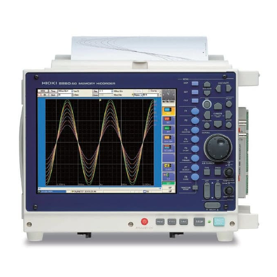
MEMORY HiCORDER
Brand:
Hioki
| Category:
Recording Equipment
| Size: 9 MB
Table of Contents
Table of Contents
3
Contents 1
13
Appendix
13
Appendix 1 Error Messages
13
Usage Index
13
Introduction
15
Reading this Manual
17
Chapter 1 Overview
19
Product Overview
19
Features
19
Appendix 2 Reference
20
Interconnection and Block Diagrams
22
Internal Block Diagram
23
Chapter 2 Operating Keys and Screen Contents
25
Operating Keys
25
Screen Organization
29
Opening Screen
30
Waveform Screen
31
Status Bar
35
Settings Screen
38
Status Settings Screen
39
Channel Settings Screen
42
Trigger Settings Screen
45
Sheet Settings Screen
46
Memory Division Settings Screen
47
Numerical Calculation (Num Calc) Settings Screen
48
Waveform Calculation (Wave Calc) Settings Screen
49
Save Settings Screen
50
Print Settings Screen
51
File Screen
52
System Screen
55
Environment (Env) Settings Screen
55
Communication (Comm) Settings Screen
56
External Terminals (Ext Term) Settings Screen
58
Setting Configuration (Setting) Screen
59
Initialization (Init) Settings Screen
60
Configuration List (Config) Screen
61
Chapter 3 Operation Overview
63
Measurement Workflow
63
Analog Waveform Recording
63
Logic Waveform Recording
67
Before Operating
68
Preliminary Settings and Verification
68
Using a Mouse
69
Using a Keyboard
70
If the Model 9719 Memory Backup Unit Is Installed
71
If the Model 9684 DC Power Unit Is Installed
72
Connection Procedure
73
Common Operations
74
Select a Function
74
To Change a Setting
74
Appendix 2.8 Keyboard Assignment Table
75
Entering Text and Numbers
76
Mouse Operations
80
Automatic Range Setting (Auto-Ranging Function)
85
Starting and Stopping Measurement
87
Disabling Key Operations (Key-Lock Function)
89
Chapter 4 Measurement Configuration Settings
91
Selecting the Function
92
Setting Measurement Configuration (Status Settings Screen)
97
Selecting Channels to Use
97
Setting the Timebase (Horizontal Axis) and Sampling Rate
101
Appendix 4.4 Recorder Function Values
103
Setting Different Sampling Rates
104
Setting the Recording Length (Number of Divisions)
107
Acquiring Waveforms Using the Utility Functions
111
Displaying Waveforms During Recording (Roll Mode)
111
Overlaying Waveforms
113
Dividing Memory
115
Setting Measurement Configuration on the Waveform Screen
120
Chapter 5 Input Channel Settings
121
Analog Channel Settings
122
Adding Comments
124
Adding a Title Comment
124
Adding Channel Comments
125
Monitoring Input Status
128
Verifying the Input Level (Level Monitor)
128
Converting Input Values (Scaling Function)
129
Verifying and Setting All Channels from a List
135
Copying Settings between Channels
139
Setting Input Channels from the Waveform Screen
140
Chapter 6 Trigger Settings
141
About Triggering
142
Setting Workflow
143
Setting the Trigger Mode
144
Setting Combining Logic (AND/OR) for Multiple Trigger Sources
145
Pre-Trigger Settings
146
Setting the Trigger Start Point (Pre-Trigger)
146
Setting Trigger Acceptance (Trigger Priority)
149
Setting Trigger Timing
150
Triggering by Analog Signals
152
About Analog Trigger Types and Settings
152
(Level Trigger)
156
Triggering When Crossing a Voltage Threshold 9
156
Triggering with Upper and Lower Thresholds (Window Trigger)
158
Triggering by Period Variance (Period Trigger)
159
Triggering by Pulse Width (Glitch Trigger)
161
Slope Trigger
162
Triggering Upon Instantaneous Voltage Sag at Commercial Mains Frequency (50/60 Hz) (Voltage Sag Trigger)
164
Triggering by Logic Signals (Logic Trigger)
165
Trigger by Timer or Time Intervals (Timer Trigger)
168
Triggering Manually (Manual Trigger)
171
Applying an External Trigger (External Trigger)
172
Making Trigger Settings on the Waveform Screen
173
Chapter 7 Waveform Display Settings
175
Making Input Waveform Display Settings (Analog Waveforms)
176
Setting Whether a Waveform Is Displayed or Hidden, and Its Color
177
Setting the Waveform Display Position (Zero Position)
178
Setting the Screen Layout of the Waveform Screen (Sheet Settings Screen)
180
Assigning Display Data to Sheets
181
Assigning a Sheet Name
183
Setting the Display Type
183
Splitting the Display Screen (Split-Screen)
184
Setting Waveform Scrolling Orientation
185
Assigning Display Channels to Graphs (Analog Channels)
186
Displaying Logic Waveforms
188
Setting the Waveform Display
189
Setting the Display Position
190
Setting the Display Height
191
Composite Waveforms (X-Y Waveforms)
192
Chapter 8 Waveform Screen Monitoring and Analysis
197
Scrolling Waveforms
198
Verifying Waveform Display Position
199
Specifying a Display Location (Jump Function)
200
Displaying Measured Values and Information
201
Applying Gauges
203
Monitoring Input Levels (Level Monitor)
204
Specifying a Waveform Range
205
Cursor Values
207
About Cursor Types and Values
207
Reading Time and Frequency (Vertical Cursors)
209
Reading Voltage Values (Horizontal Cursors)
211
Reading Time and Voltage Values (Trace Cursor)
212
Reading Cursor Values of X-Y Waveforms
214
Magnifying and Compressing Waveforms
216
Magnifying and Compressing Horizontally (Time Axis)
216
Magnifying and Compressing Vertically (Voltage Axis)
217
Magnifying a Section of the Horizontal Axis (Time Axis - Zoom Function)
218
Setting Arbitrary Waveform Height and Position on the Vertical (Voltage) Axis (Variable Function)
220
Fine Adjustment of Input Values (Vernier Function)
223
Viewing Past Waveforms
224
Viewing Waveforms in Every Display Block (Memory Division)
225
Viewing Waveform Data as Numerical Values
226
Searching a Waveform
227
Searching by Trigger Criteria
228
Searching by Time
233
Searching for Peaks
234
Chapter 9 Measuring with Real-Time Saving
237
Overview of the Real-Time Saving Function
237
Setting and Analysis Workflow
239
Saving Settings
242
Pre-Measurement Settings
244
Analyzing Data
250
Waveform Viewing
250
Calculating
254
Chapter 10 Saving/Loading Data & Managing Files
255
Storage Media
256
Using a PC Card
256
Using an MO Disk
257
Using a Floppy Disk
259
Using a Hard Disk
260
Using USB Memory Devices
260
Using a Network Shared Folder
261
Initializing (Formatting) Storage Media
263
Data Capable of Being Saved & Loaded
264
File Sizes
265
File Names
267
Saving Data
269
Save Sequence
269
Save Methods
270
Specifying the Save Destination
272
Setting Auto Save
273
Setting Manual Save (SAVE Key Output)
275
Saving Settings Data
277
Automatically Saving Waveforms
279
Optionally Selecting Waveforms & Saving (SAVE Key)
282
Automatically Saving Display Images
284
10Optionally Selecting Display Screens & Saving (SAVE Key)
286
Loading Data
287
Selecting Files & Folders on Storage Media
288
Loading Settings Data
290
Loading Waveform Data
291
Saving & Loading Auto Settings File (Auto Setup Function)
292
Examples of Saving Data: Reading Data on a PC
294
Example of Saving Data
294
Reading Waveform Data on a PC
298
Managing Files
300
Copying Files & Folders
301
Moving Files & Folders
302
Deleting Files & Folders
303
Renaming Files & Folders
303
Creating New Folders
304
Sorting Files
305
Limiting Display of Files
306
Setting the Items to Display
307
Printing the File List
308
Chapter 11 Printing
309
Printing Workflow
310
Print Methods and Print Items
311
Making Auto Print Settings
313
Making Manual Print (PRINT Key Output) Settings
315
Making Printer Settings
319
Internal Printer Settings
319
External Printer Settings
321
Setting the Print Content
323
Common Settings
323
Printing Waveforms
325
Printing Numerical Value Displays
330
Making Gauge Settings (When Using External Printer)
332
Printing Comments and Setting Data
333
Print Examples
335
Chapter 12 System Environment Settings
345
Making Waveform Screen Display Settings
346
Selecting the Grid Type
346
Displaying or Hiding Comments
347
Selecting the Time Value Display
348
Displaying Zero Position
348
Making Key Operation and Operational Settings
349
Specifying Activation Conditions for the START Key
349
Using the Auto-Resume Function (Resume after Power Restoration)
350
Specifying Jog & Shuttle Scroll Operations
351
Using Sheet Scroll Linkage
352
Specifying SHEET/PAGE Key Operations
352
Selecting How Settings Affect Measurement (Restart Permission)
353
Performing Variable Function Auto Adjustment
353
Specifying Beep and Operation Sounds
354
Making Screen Saver Settings
355
10Making Backlight Saver Settings
356
11Selecting the Display Language
357
12Selecting Screen Colors
358
Making System Settings
359
Setting the Date and Time
359
Initializing Waveform Data
360
Initializing System Settings (System Reset)
361
Self-Test (Self Diagnostics)
362
Adjusting the 8958 16-Ch Scanner Unit
368
System Configuration List
369
Chapter 13 Communications Settings
371
Connection Configurations
372
Controlling the Instrument over the LAN Interface
374
Settings and Connection Procedure
374
Making Settings on the Instrument
375
Using FTP to Access Instrument Files (FTP Server)
381
Making Settings on the Instrument
381
Operate on the PC
383
Performing Remote Operations on the Instrument from an Internet Browser (Web Server)
386
Making Settings on the Instrument
386
Operate on the PC
388
Using an Interface Card
392
Controlling the Instrument with Command Communications
393
Making Settings on the Instrument
393
Operate on the PC
396
Chapter 14 External Control
399
Connecting External Control Terminals
400
External I/O
402
External Trigger Input ( EXT TRIG )
402
Trigger Output ( TRIG out /CAL)
404
External Sampling (EXT.SMPL)
406
Synchronized Sampling Output (SYNC.OUT)
408
GO/ NG Evaluation Output ( GO / EXT OUT1 )
411
Ng Ext Out2
411
External Output ( GO / EXT OUT1 )
413
GO/ NG Evaluation Output ( GO / EXT OUT1 )/ ( NG / EXT OUT2 )
414
External Input
415
( Print / Ext.in3 )
415
Probe Calibration Signal Output ( TRIG out /CAL)
417
Chapter 15 Specifications
419
General Specifications
419
Trigger Section
425
Memory Function
427
Recorder Function
429
FFT Function
431
Real-Time Saving Function
432
Functions
433
Practical Functions
433
Miscellaneous Functions
433
System Settings
452
Advertisement
Hioki 8860 Manual (114 pages)
INPUT MODULE MEMORY HiCORDER
Brand:
Hioki
| Category:
I/O Systems
| Size: 1 MB
Table of Contents
Table of Contents
5
Introduction
9
Structure of this Document
11
Chapter 1 Overview
13
Product Overview
13
Input Module Usage List
17
List of Input Modules, Cables, Probes and Clamp Combinations
19
Chapter 2 Connections
21
Installing Input Modules (Adding or Replacing)
22
Connecting the Cables
24
Connection Preparations
24
Connecting to an Analog Unit (Models 8936, 8938, 8946, 8956 and 8957)
25
Connecting to the Model 8937 Voltage/Temp Unit
26
Connecting to a Strain Unit (Models 8939 and 8960)
28
Connecting to the Model 8940 F/V Unit
29
Connecting to the Model 8947 Charge Unit
32
Connecting to the Model 8958 16-Ch Scanner Unit
34
Connecting to the Model 8959 DC/RMS Unit
36
Connecting Clamps
37
Connecting a Differential Probe
39
Connecting Attenuating Probes
43
Connecting Logic Probes
45
Supplying Power from the Model 9687 Probe Power Unit
49
Chapter 3 Input Channel Settings
51
Analog Unit Settings (Models 8936, 8946 and 8956)
52
Model 8937 Voltage and Temperature Unit Settings
53
Voltage Measurement
53
Temperature Measurement
54
Model 8938 FFT Analog Unit Settings
56
Strain Unit Settings (Models 8939 and 8960)
57
Model 8940 F/V Unit Settings
58
Measuring Frequency, 50/60 Hz and Rotation Rate
58
Pulse Count Measurement
60
Pulse Duty Measurement
61
Voltage Measurement
62
Current Measurement
63
Model 8947 Charge Unit Settings
64
Voltage Measurement
64
Acceleration Measurement (Charge, Preamp)
65
Model 8957 High Resolution Unit Settings
67
Model 8958 16-Ch Scanner Unit Settings
68
Voltage Measurement
68
Temperature Measurement
69
Model 8959 DC/RMS Unit Settings
71
About Setting Contents
72
Measurement Range Setting
72
Setting Input Coupling
73
Low-Pass Filter (LPF) Settings
74
Anti-Aliasing Filter (AAF) Settings
75
Digital Filter (Digital F) Settings
75
Thermocouple (Sensor) Type Setting
76
Reference Junction Compensation Setting
76
Drift Correction Setting
77
Disconnect (Burn-Out) Detection Setting
77
Hold Setting
78
Pull-Up Setting
79
Threshold Setting
80
Response (Timing) Setting
80
Sensor Sensitivity Setting
81
Probe Attenuation Selection
83
Bridge Voltage Setting
83
Executing Zero Adjustment
84
Executing Offset Cancellation
84
Executing Auto-Balance
86
Chapter 4 Logic Input Settings
87
Operation Overview
87
Setting Procedure
88
Chapter 5 Specifications
91
Logic Input Section
91
Model 9327 Logic Probe
91
Model 9321-01 Logic Probe
92
Model 9320-01 Logic Probe
93
Analog Input Section
94
Model 8936 Analog Unit
94
Model 8937 Voltage/Temp Unit
96
Model 8938 FFT Analog Unit
98
Model 8939 Strain Unit
99
Model 8940 F/V Unit
100
Model 8946 4-Ch Analog Unit
102
Model 8947 Charge Unit
103
Model 8956 Analog Unit
105
Model 8957 High Resolution Unit
106
Model 8958 16-Ch Scanner Unit
107
Model 8959 DC/RMS Unit
109
Model 8960 Strain Unit
110
Index
111
Hioki 8860 Quick Start Manual (110 pages)
MEMORY HiCORDER
Brand:
Hioki
| Category:
Data Loggers
| Size: 3 MB
Table of Contents
Table of Contents
3
Appendix
5
Introduction
5
Confirming Package Contents
6
Safety Information
7
Operating Precautions
9
Chapter 1 Overview
15
Product Overview and Features
15
Measurement Workflow
16
Chapter 2 Names and Functions of Parts
23
Panel Names and Functions
23
Screen Types and Contents
27
Basic Operations
36
To Change Settings
36
Entering Text and Numbers
37
Viewing Recorded Data
39
Chapter 3 Measurement Preparations
41
Installation & Connection Procedures
41
Connecting Cables and Probes
42
Loading Recording Paper (with a Printer Module Installed)
46
Connecting the Power Cord
49
Grounding the Instrument's Functional Earth
49
Turning the Power on and off
50
Setting the Clock
52
Chapter 4 Basic Operations
53
Pre-Measurement Inspection
53
Operation Workflow
54
Recording Simple Waveforms
55
Actual Measurement and Analysis
58
Chapter 5
61
Chapter 5 Saving & Loading Data
69
Recording (Storage) Media
70
Using PC Cards
71
Data that Can be Saved & Loaded
72
Saving Procedures and Contents
74
Data Saving
75
Data Loading
78
Chapter 6 Printing
79
Printing Methods and Contents
80
Printing While Recording (Auto Print)
81
Manual Printing (PRINT Key)
82
To Print a Detailed Settings List
83
Chapter 7 Maintenance and Service
85
Troubleshooting
85
Cleaning
88
Appendix 1 Waveform Screen Display & Icons
91
Appendix 2 Overview of Settings and Functions
92
Appendix 3 Common Questions
97
Index
103
Advertisement
Advertisement
Related Products
Hioki 8861
Hioki 8423
Hioki MICRO HiCORDER 8206-10
Hioki 8860-50
Hioki 8861-50
Hioki 8847
Hioki 8846
Hioki 3631-20
Hioki 3632-20
Hioki 3633-20
Hioki Categories
Measuring Instruments
Test Equipment
Data Loggers
Multimeter
Accessories
More Hioki Manuals
Login
Sign In
OR
Sign in with Facebook
Sign in with Google
Upload manual
Upload from disk
Upload from URL