
Related Manuals for Hioki 3640-20


Summary of Contents for Hioki 3640-20
- Page 1 INSTRUCTION MANUAL For...は専用機種。複数の場合は「/」で区切る。 不要の場合はとる。 形名を入力。 複数の場合は「/」で区切る。 3640-20 品名を入力。 LUX LOGGER...
-
Page 3: Table Of Contents
Contents Introduction Inspection Safety Notes Notes on Use Measurement Flow Chart and Reference Guide Chapter 1 Product Overview 1.1 Name and Functions of Parts 1.2 Interval and Maximum Recording Time Chapter 2 Set Up 2.1 Replacing the Battery 2.2 Power Save Function 2.3 Setting Current Time 2.4 Connecting 9662 LUX SENSOR Chapter 3 Settings... - Page 5 _____________________________________________________________________ Introduction Thank you for purchasing this HIOKI "3640-20 LUX LOGGER." To get the maximum performance from the unit, please read this manual first, and keep this at hand. ______________________________________________________________ Introduction...
-
Page 6: Inspection
Before using the product the first time, verify that it operates normally to ensure that the no damage occurred during storage or shipping. If you find any damage, contact your dealer or Hioki representative. Testing monitor batteries installed in the unit may possibly be NOTE weak. -
Page 7: Safety Notes
_____________________________________________________________________ Safety Notes This equipment is designed according to IEC 61010-1 Safety Standards, and has been tested for safety prior DANGER to shipment. Incorrect measurement procedures could result in injury or death, as well as damage to the equipment. Please read this manual carefully and be sure that you understand its contents before using the equipment. - Page 8 _____________________________________________________________________ The following symbols are used in this Instruction Manual to indicate the relative importance of cautions and warnings. Indicates that incorrect operation presents extreme danger of accident resulting in death or serious injury DANGER to the user. Indicates that incorrect operation presents significant danger of accident resulting in death or serious injury WARNING to the user.
-
Page 9: Notes On Use
_____________________________________________________________________ Notes on Use In order to ensure safe operation and to obtain maximum performance from the unit, observe the cautions listed below. Do not store or use the product where it could be exposed CAUTION to high temperature or humidity, or condensation. Under such conditions, the product may be damaged and insulation may deteriorate so that it no longer meets specifications. -
Page 10: Measurement Flow Chart And Reference Guide
Measurement Flow Chart and Reference Guide Is there sufficient Replace batteries battery charge remaining See 2.1. to operate 3640-20? Set current time when using 3640-20 for the Setting current time first time or replacing batteries. See 2.3. Connecting sensor See 2.4. Zero ajustment See 2.4. -
Page 11: Chapter 1 Product Overview
1 channel of data at illuminance. Data is saved in nonvolatile memory when batteries are weak or removed for replacement. 3640-20 LUX LOGGER are not able to set up it to 3910-20 NOTE COMMUNICATION BASE. Use 3911-20, 3912-20 COMMUNICATION BASE to set 3640-... -
Page 12: Name And Functions Of Parts
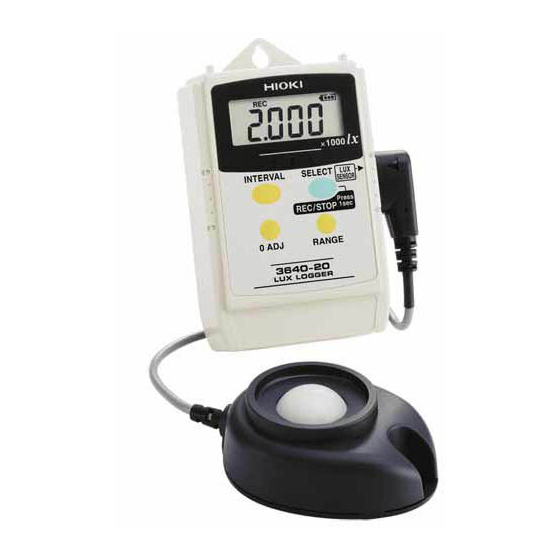
_____________________________________________________________________ 1.1 Name and Functions of Parts REC/STOP button Optical data (SELECT) button transfer ports INTERVAL Sensor connection button terminal Zero ajustment button Range button Displays measurement value and settings. Optical data Enables optical data transfer to transfer ports COMMUNICATION BASE. INTERVAL button Calls up interval setting display to set interval. -
Page 13: Interval And Maximum Recording Time
_____________________________________________________________________ 1.2 Interval and Maximum Recording Time Interval and maximum recording time (when power save function is valid) are as follows. Maximum recordable data is 32000 per unit. INTVL Maximum Recording Time 8 h 53 min 20 s 17 h 46 min 40 s 1 day 20 h 26 min 40 s 10 s 3 day 16 h 26 min 40 s... - Page 14 _____________________________________________________________________ ______________________________________________________________ 1.2 Interval and Maximum Recording Time...
-
Page 15: Chapter 2 Set Up
_____________________________________________________________________ Chapter 2 Set Up 2.1 Replacing the Battery During battery replacement, use caution not to put any foreign materials such as a metal object into the unit to WARNING avoid damage to the unit. Before using the product after replacing the batteries, replace the cover and screw. - Page 16 _____________________________________________________________________ 1. Remove back cover screw to remove cover. Verify polarity and install four new LR03 alkaline batteries. 2. Fit cover properly and tighten screw. ______________________________________________________________ 2.1 Replacing the Battery...
-
Page 17: Power Save Function
_____________________________________________________________________ 2.2 Power Save Function Display window is automatically turned off in approximately 15 seconds after last key entry. (Sleep) However, while recording, mark shows each conditions. Sleeping..Press any button to turn display on to display measurement value or to set settings. Note when interval setting display is on, sleep does not engage with no button press. -
Page 18: Setting Current Time
_____________________________________________________________________ 2.3 Setting Current Time When replacing 3640-20 LUX LOGGER batteries or using 3640-20 stand-alone (with manual operation) for the first time, connect with COMMUNICATION BASE and set current time. See how to set current time in COMMUNICATION BASE instruction manual. -
Page 19: Connecting 9662 Lux Sensor
_____________________________________________________________________ 2.4 Connecting 9662 LUX SENSOR To avoid damaging the unit, do not use any other sensors except 9662 LUX SENSOR as sensor WARNING connection terminal. Connecting 9662 LUX SENSOR Connecting 9662 LUX SENSOR to sensor connection terminal.When connecting sensor, securely insert connection cable to unit as designated by triangle mark ▲... - Page 20 _____________________________________________________________________ Electromagnetic noise may cause measurements to fluctuate if the instrument is used in the vicinity of an inverter-type power supply or radio transmitter. In such situations, make a loop in the Lux Sensor cable and clamp the provided ferrite core around the loop as shown in the illustration below.
-
Page 21: Chapter 3 Settings
_____________________________________________________________________ Chapter 3 Settings 3.1 Setting Items Logger stand-alone manual settings and settings in combination with COMMUNICATION BASE with measurement conditions stored in memory loaded from personal computer. 3640-20+ 3640-20+ 3640-20 COMMUNICATION COMMUNICATION BASE BASE+PC 1. Start recording Vaild Vaild Vaild 2. - Page 22 _____________________________________________________________________ 1. Start recording Start manual recording by pressing logger REC/STOP button for 1 second or initiate by prescheduled start set using COMMUNICATION BASE. When time scheduled start is engaged, clock icon appears in display. When batteries are weak, recording does not start.
- Page 23 _____________________________________________________________________ 7. Range setting With 3640-20 stand-alone, or connected with COMMUNICATION BASE and PC, range setting is available. Two measurement range options are 2000 lx, 20000 lx and 2000000 lx. Set the range comply with the maximum illuminance will be measured.
-
Page 24: Manual Setting
_____________________________________________________________________ 3.2 Manual Setting 3640-20 LUX LOGGER stand-alone manual operation settings are shown below. (1) Interval setting Press INTERVAL button to switch measurement value display to interval setting display. (" " appears.) INTVL Press SELECT button to designate interval. Press INTERVAL button to complete setting. - Page 25 _____________________________________________________________________ (3) Starting and ending recording Press REC/STOP button for 1 second to clear last recorded data and start recording. (" " appears.) Press REC/STOP button for 1 second to stop recording. When memory is full, recording automatically stops when recording method: one time is selected.
-
Page 26: Setting By Communication Base
_____________________________________________________________________ 3.3 Setting by COMMUNICATION BASE 1. Press logger INTERVAL button lightly to display LCD. 2. When logger LCD shows " " mark or clock icon, press REC/STOP button for more than 1 second to stop recording. During recording or waiting time before recording start time, data transfer cannot be established with COMMUNICATION BASE. - Page 27 '3640-20 setting items' to set settings. Comment, recording mode, measurement channel, range and NOTE alarm setting are only available in 3640-20 setting items. Personal computer, COMMUNICATION BASE and 3640-20 must be connected during setting. Common settings are available to be set in '3911, 3912 setting items'.
- Page 28 _____________________________________________________________________ ______________________________________________________________ 3.3 Setting by COMMUNICATION BASE...
-
Page 29: Chapter 4 Specifications
_____________________________________________________________________ Chapter 4 Specifications Sensor types 9662 LUX SENSOR Number of input 1 channel Measurement 0 to 200000 lx range Range structure 2000 lx/20000 lx/200000 lx Measurement 4% rdg. 5 dgt. (after zero ajustment) accuracy Temperature characteristics : Temperature properties: When measuring within the range 0 to 40 , variance is within 3% of the measurement at 23 . - Page 30 _____________________________________________________________________ Dimensions Approx. 57W X 86H X 30D mm (excluding projections) 2.24"W X 3.39"H X 1.18"D Mass Approx. 130 g (4.6 oz) (including batteries) Location for use Indoors, altitude up to 2000 m (6562 feet) Operate 0 to 40 , 80% RH or less (no condensation) temperature and (32 to 122 ) humidity range...
-
Page 31: Chapter 5 Reference
_____________________________________________________________________ Chapter 5 Reference 5.1 Recommended Levels of Illumination Suitable levels of illuminance (According to the JIS standard Z 9110-1979) Offices Level of Place illuminance (lx) Offices, designing, and drawing rooms 1500 to 750 Offices, conference rooms, and computer 750 to 300 rooms Workrooms, corridors, stairways, and 300 to 100... - Page 32 _____________________________________________________________________ Factories Level of Place illuminance (lx) Where such work as assembling, inspecting, 3000 to 1500 testing, selecting and extremely precision visual work Assembling, inspecting, testing, selecting and 1500 to 750 precision visual work Assembling, inspecting, testing, selecting and 750 to 300 visual ordinary work Wrapping and packing 300 to 150...
-
Page 33: Relative Spectral Response Characteristics In The Visible Spectrum
1 and indicating the amount of perception of each wavelength by the relative value, and calculating the average of many people. In the 3640-20, the relative spectral response characteristics are close to the comparative standards for luminosity. -
Page 34: Angled Incident Light Characteristics
It is known that the luminance is proportional to the cosine of the incident angle of light (the cosine law). In the 3640-20, the shape of the light sensor, hook etc. is so made that it can follow the cosine law closely. -
Page 35: Chapter 6 Maintenance And Service
Pack the product carefully so that it will not be damaged during shipment, and include a detailed written description of the problem. Hioki cannot be responsible for damage that occurs during shipment. Error Messages The following error may be displayed on the LCD of the main instrument as shown below. - Page 36 _____________________________________________________________________ ______________________________________________________________...
- Page 39 HIOKI 3640-20 LUX LOGGER Instruction Manual Publication date: May 2008 Revised edition 5 Edited and published by HIOKI E.E. CORPORATION Technical Support Section All inquiries to International Sales and Marketing Department 81 Koizumi, Ueda, Nagano, 386-1192, Japan TEL: +81-268-28-0562 / FAX: +81-268-28-0568 E-mail: os-com@hioki.co.jp...
- Page 40 HEAD OFFICE 81 Koizumi, Ueda, Nagano 386-1192, Japan TEL +81-268-28-0562 / FAX +81-268-28-0568 E-mail: os-com@hioki.co.jp / URL http://www.hioki.com/ HIOKI USA CORPORATION 6 Corporate Drive, Cranbury, NJ 08512, USA TEL +1-609-409-9109 / FAX +1-609-409-9108 3640A981-05 08-05H Printed on recycled paper...
Need help?
Do you have a question about the 3640-20 and is the answer not in the manual?
Questions and answers